| Energy Engineering |
DOI: 10.32604/ee.2022.018233
ARTICLE
Grid-Connected Control Strategy of VSG under Complex Grid Voltage Conditions
School of Automation & Electrical Engineering, Lanzhou Jiaotong University, Lanzhou, China
*Corresponding Author: Yanjun Jin. Email: jyj19893175170@163.com
Received: 09 July 2021; Accepted: 24 September 2021
Abstract: Under complex grid conditions, the grid voltage usually has an imbalance, low order harmonics, and a small of DC bias. When the grid voltage contains low order harmonics and a small amount of DC bias component, the inverter's output current cannot meet the grid connection requirements, and there is a three-phase current imbalance in the control strategy of common VSG under unbalanced voltage. A theoretical analysis of non-ideal power grids is carried out, and a VSG control strategy under complex operating conditions is proposed. Firstly, the third-order generalized integrator (TOGI) is used to eliminate the influence of the DC component of grid voltage. An improved delay signal cancellation (DSC) method is proposed to control the balance current and power fluctuation under unbalanced voltage based on the method of common VSG positive and negative sequence separation, It also eliminates the harmonic of command current. Then, the improved quasi proportional resonant controller (QPR) cascaded PI is used to suppress the harmonic current further so that the harmonic content of grid-connected current can meet the grid-connected requirements and achieve the three-phase current balance. Finally, the proposed strategy is verified by simulation under the control objectives of the current balance, active power, and reactive power constant.
Keywords: Complicated condition; harmonic elimination; VSG control; DC component; quasi-proportional resonance; sequence current control
With the rapid development of new energy and high level accesses to the distribution network, the damping and inertia of the power system also decrease accordingly. The common grid-connected inverter has defects in providing frequency and voltage support for the power grid. Therefore, it cannot meet the power system's frequency, and voltage regulation performance with a large number of distributed generation penetration. As a result, the stability problem of power system is becoming increasingly serious. Therefore, when the distributed generation is connected to the grid, it should also support the grid voltage and frequency actively. In recent years, the application of virtual synchronous generator (VSG) grid-connected inverter control in the field of new energy has attracted attention [1–4]. The synchronous generator port voltage characteristics, provide the corresponding inertia and damping support for the grid when the distributed generation is connected to the grid [5–9]. Auxiliary inertia and additional power are introduced into VSG, which reduces the difference between VSG and SG and improves transient stability [10,11].
However, most of the research on VSG is based on the condition of three-phase voltage balance. However, in the actual operation of the power system, the grid voltage is usually affected by various factors, resulting in three-phase voltage imbalance, DC bias component and harmonic content. When the grid voltage is unbalanced, including DC component and harmonic content, VSG will have grid-connected current distortion and output active power and reactive power oscillation just like an ordinary inverter. In reference [12], it is proposed to reshape the voltage admittance of the power grid and use the voltage feed-forward of the power grid to suppress the current harmonics. Still, there is no research on the unbalanced power grid and the DC component. In reference [13], the VSG control strategy is mainly studied from the perspective of limiting over-current. In reference [14], the strategy of suppressing harmonic resonance by series resistance or parallel resistance of filter capacitor is proposed. Wan et al. considered in-depth research on the power grid voltage imbalance, but did not further discuss that the power grid voltage contains harmonics and small DC components [15]. In the two-phase static coordinate system, the positive sequence and negative sequence of grid voltage are decomposed to realize the coordinated control of power and current and improve the operation performance of the system [16]. When the power grid voltage contains harmonics and a small DC component, its control strategy will fail. Hu et al. considered virtual impedance based on positive and negative sequence control of output current, which can limit the fault current when the grid voltage drop [17]. The suppression of power grid harmonic and the elimination of DC components are not discussed. In reference [18], the improved PR controller is applied to the harmonic suppression of PMSM. Xiao et al. used a second-order generalized integrator to separate the positive and negative sequence of voltage and current [19]. When the power grid voltage is unbalanced, it is verified according to different control objectives, but the control strategy will fail when it contains DC component. In reference [20], an active damping control strategy is proposed based on the voltage and current's positive and negative sequence components. The current harmonic is suppressed, but this strategy fails when the grid voltage contains a DC component. Shi et al. proposes that in case of power grid failure, PR current control algorithm is used to limit the power grid current and provide reactive power to the power grid [21]. The phase angle feedback tracking synchronization strategy is adopted to improve the transient performance of the switching process. This strategy will not achieve the control goal when the power grid contains a DC component.
The control strategies proposed in the above literature do not consider the unbalanced grid voltage, harmonic and DC components. Considering the above situation, this paper takes the three-phase balance of output current and constant power as the control objectives when the grid voltage of VSG grid-connected inverter is unbalanced and contains harmonics and a small DC components. It proposes a pre-third-order generalized integrator to eliminate DC components. The improved DSC achieves the current command balance and harmonic elimination based on the VSG control strategy under common voltage imbalance [22]. The improved quasi proportional resonance (QPR) controller cascaded with PI controls the command current. Control strategy when the grid voltage is unbalanced and contains harmonics and DC components simultaneously, or under any of the non-ideal conditions, the control goal can be achieved without selecting the control strategy according to the type of non-ideal grid voltage. Finally, the correctness of the proposed strategy is verified by Simulink simulation in the case of unbalanced grid voltage, harmonic, and DC components.
2 Analysis of Voltage Composition and Power Fluctuation of the Power Grid
Assuming that the grid voltage is not ideal, that is, including DC offset component, three-phase voltage imbalance, and each harmonic component, the three-phase grid voltage can be expressed as
where: k = a, b, v; e0k is DC component; eh+ (eh−) is the positive (negative) sequence voltage amplitude; h is the number of harmonics; θhk+( θhk−) is the positive (negative) sequence phase of k-phase voltage.
The third-order generalized integrator can eliminate the DC component of the non-ideal grid voltage in the three-phase static coordinate system. After eliminating the DC component, the non-ideal grid voltage can be expressed as
It can be seen from reference [23] that after the grid voltage is transformed through 3 s/2r coordinate, the h-th harmonic will be transformed into h + 1 or h − 1 harmonic.
When the grid voltage is unbalanced, the expressions of instantaneous active power and reactive power are as follows:
where:
where edq is the component of grid voltage in the dq coordinate system, the superscript “-” represents negative sequence component, and the superscript “+” represents the positive sequence component.
The essence of fractional VSG is to simulate the output characteristics of a synchronous generator, so that the grid-connected inverter can have the characteristics and advantages of a synchronous generator. The overall block diagram of the main circuit of fractional VSG is shown in Fig. 1. In Fig. 1, udc is DC side voltage, Zs is inverter side impedance, C is filter capacitor, and Zg is grid side impedance. ia, ib and ic are the output current of the inverter, ua, ub and uc are the output voltage of the inverter, and P* and Q*are the initial set values of the output active and reactive power.
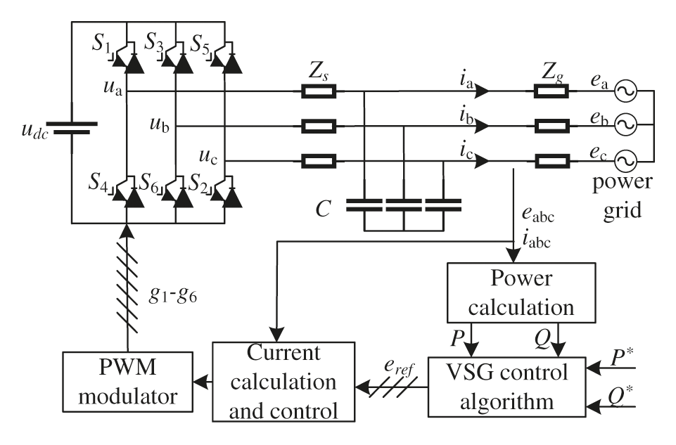
Figure 1: Overall block diagram of VSG main circuit
During grid-connected operation, the VSG power frequency and excitation control loop transmits power to the grid according to the initial set of active and reactive power.To calculate the reference phase and frequency, the active power loop of VSG simulates the primary frequency modulation, damping and inertia of SG. As the power system frequency must be within the allowable range, to meet this requirement, the VSG power frequency control loop must analyze the influence of frequency deviation on VSG. As a virtual synchronous motor, the frequency can be adjusted as long as the mechanical torque is controlled. In terms of power, the frequency can also be adjusted by controlling the output power and the given power, as shown in Eq. (4); Then the phase angle of the inverter side output voltage is adjusted according to the mechanical equation of the synchronous generator θ.
where f, f0and kf are the voltage frequency of inverter terminal, the reference frequency of the power grid and the frequency deviation adjustment coefficient, respectively.
VSG excitation control loop adjusts the output reactive power and voltage amplitude of grid-connected inverter, as shown in Eq. (5); The voltage amplitude e obtained by the excitation control loop and the phase angle obtained by the power frequency control loop are used θ The synthetic reference voltage uref is shown in Eq. (6), while the VSG control block diagram is shown in Fig. 2.
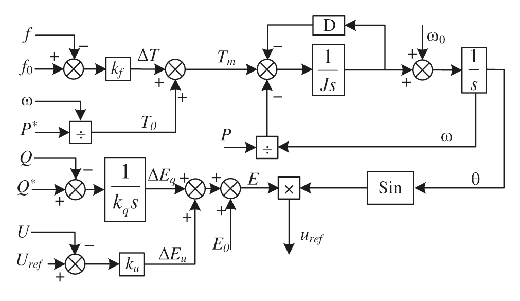
Figure 2: Block diagram of VSG control
4 VSG Control Strategy under Complex Conditions
4.1 Reference Current Calculation
According to Eq. (3), current balance or constant power control can be realized under unbalanced grid voltage by controlling the values of positive and negative sequence currents. The calculation of the current reference value is the core part of the whole control, which is the key to realize current balance and power oscillation suppression. Therefore, the calculation method of the current reference value is introduced below.
According to Fig. 1, the relationship between the output voltage and current of inverter is established without considering the effect of the capacitor, as shown in Eq. (7):
where L and R are the total inductance and the total resistance from the inverter to the grid, respectively.
The output voltage uabc of the inverter side is decomposed into dq by the d-axis orientation of the grid voltage, and the relationship between voltage and current in the dq coordinate system is as follows:
If Eq. (8) is transformed into complex frequency domain calculation, the expression of current reference instruction is as follows:
where erefd and erefq are d-axis and q-axis components of voltage command eref;
The positive and negative sequence separation control of grid voltage is adopted to nsure the three-phase current balance. The TOGI module is added before the positive and negative sequence separation module of grid voltage to eliminate the influence of the DC component. A modified DSC after the positive sequence current command is used to obtain a new current command and to eliminate the harmonic component in the current command. The calculation block diagram of the improved positive sequence current command is shown in Fig. 3.
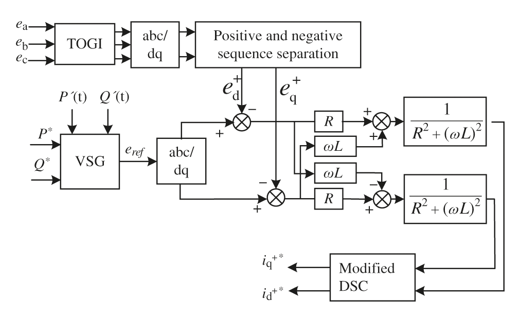
Figure 3: Improved calculation block diagram of positive sequence current command
4.2 Elimination of DC Component by Third-Order Generalized Integrator
Assume that the input signal is
Then the output of the third-order generalized integrator (TOGI) is
It can be seen from (11) that the DC bias component in u1∞(t) is eliminated, and the amplitude and phase are consistent with the AC quantity of the input signal. Thus, the influence of the DC component on the current command calculation can be eliminated according to TOGI. The structure of TOGI is shown in Fig. 4.
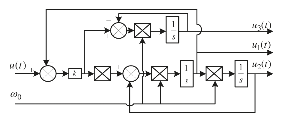
Figure 4: TOGI structure block diagram
The transfer function of traditional DSC in s domain is
where n is the delay coefficient, and T is the fundamental period of the grid.
To eliminate harmonics, traditional DSC usually consists of multiple DSCn in series [24], and only odd harmonics can be filtered. In this paper, it is necessary to eliminate Even harmonics in the dq coordinate system should be eliminated, to improve traditional DSC. The modified DSC (MDSC) function expression is as follows:
The modified DSC function has ns and n variables, which can better design the required frequency characteristics. In this paper, n = 4 and ns = 1 are used. The function expression of MDSC is
Its implementation in the time domain can be simplified as shown in Fig. 5.
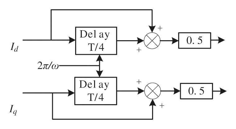
Figure 5: Time domain implementation block diagram of MDSC
The Bode diagram of MDSC is shown in Fig. 6.
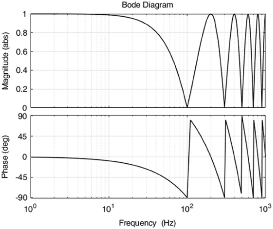
Figure 6: Bode diagram of MDSC
It can be seen from Fig. 6 that the modified DSC can completely filter even harmonics such as 100, 300 and 500 Hz.
4.4 Calculation of Current Negative Sequence Instruction
4.4.1 Control the Balance of Three-Phase Current
In order to make the output current follow the current reference value mentioned above, the output current of VSG will keep balance. At this time, the negative sequence current instructions id-*and iq-* are all zero.
4.4.2 Control the Active Power Constant
When the active power must be constant, it can be seen from Eq. (3). The amplitudes of active power fluctuation components Ps2 and Pc2 need to be zero
Then when the active power is constant, the negative sequence current command can be obtained from Eq. (15)
4.4.3 Control the Constant Reactive Power
When the reactive power must be constant, the amplitudes of the reactive power fluctuation components Qs2 and Qc2 need to be zero
When the reactive power is constant, the negative sequence current command can be obtained from Eq. (17)
4.5 Current Inner Loop Improved QPR Cascade PI Control
The ideal proportional resonance (PR) regulator has infinite gain at the resonance frequency, and can realize the static error-free tracking of AC signal, but it has a certain influence on the system's stability. Therefore, this paper adopts the QPR regulator. The transfer function of QPR is as follows
where kQPR is the proportional coefficient and kr is the integral time coefficient; ω0 represents the resonant frequency; ωc is the cut-off frequency.
QPR at resonant frequency ω0 The gain is
It can be seen from Eq. (20) that for the frequency of ±ω0 The gain of kQPR + kr can be obtained by the QPR regulator.
For AC input, at resonant frequency ω0 When only PI regulator is used in the current controller, the gain is
This paper adopts the improved QPR cascade PI control strategy with harmonic control to eliminate the 5th, 7th, 11th, and 13th harmonics in a three-phase static coordinate system, that is, the 6th and 12th harmonics in the dq coordinate system. The structure block diagram is shown in Fig. 7.
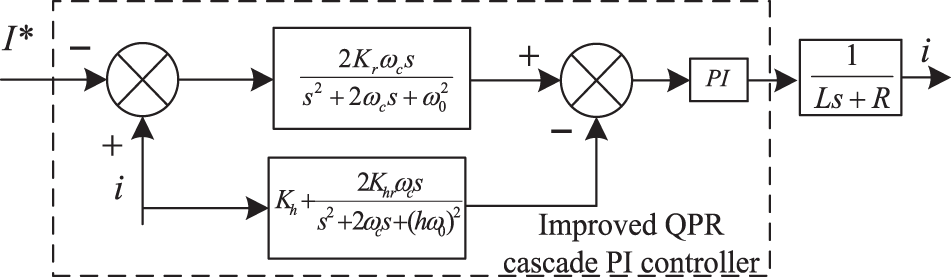
Figure 7: Improved QPR cascade PI control block diagram
The proportional term of the fundamental control part QPR is removed to reduce the gain of the non-resonant point,. According to Fig. 7, the transfer function of the reference current to the output current is expressed as
where:
The bode diagram corresponding to Eq. (22) is shown in Fig. 8.
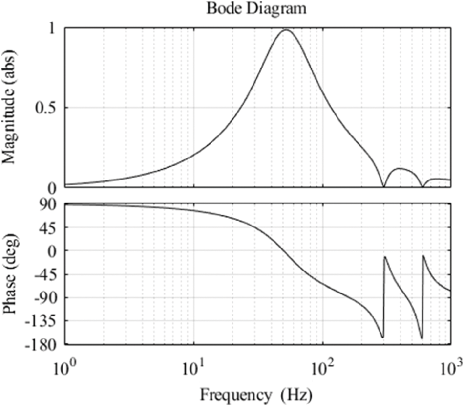
Figure 8: Bode diagram of improved QPR cascade PI
Fig. 8 shows that the closed-loop transfer function of reference current to output current gains 1 at 50 Hz of the base wave current, zero phase response, low gain outside the resonance point, and zero gain at the 6th and 12th harmonic. It can be seen that the improved QPR cascade PI control strategy can track the fundamental current in the reference instruction without static difference and effectively suppress the harmonic current. The improved positive sequence current inner loop controller block diagram is shown in Fig. 9.
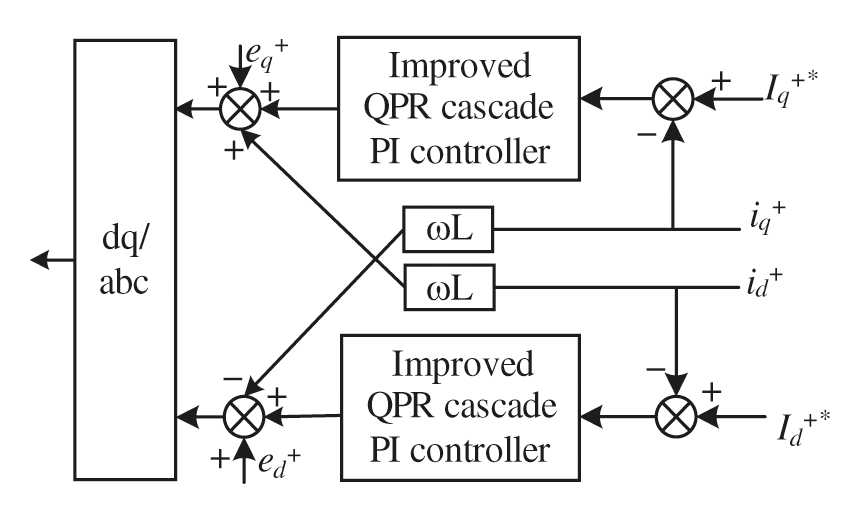
Figure 9: Improved positive sequence current inner loop controller block diagram
Similarly, the negative sequence current inner loop control block diagram is consistent with the positive sequence current inner loop control block diagram, and the control quantity is the negative sequence component.
The simulation results show that the traditional current control strategy and the improved balanced current control strategy proposed in this paper are simulated by Matlab/Simulink software. The simulation parameters are as follows (Table 1).
First, the balance current control is taken as the goal. The simulation duration is 2 s. The grid voltage is normal within 0∼0.5 s, the voltage amplitude of phase A drops to 240 V within 0.5∼1 s, and the grid voltage contains 5 times, 7 times, and 11 times. Sub-harmonics within 1∼1.5 s, the power grid A phase contains 15 V DC component within 1.5∼2 s.
Fig. 10 shows the three-phase current waveform under common VSG control balanced current under unbalanced voltage.
It can be seen from Fig. 10 that common VSG control balanced current under unbalanced voltage when the power grid is normal. The current can achieve a three-phase balance with a current amplitude of 32.4 A.
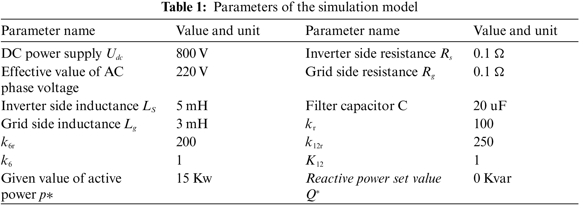
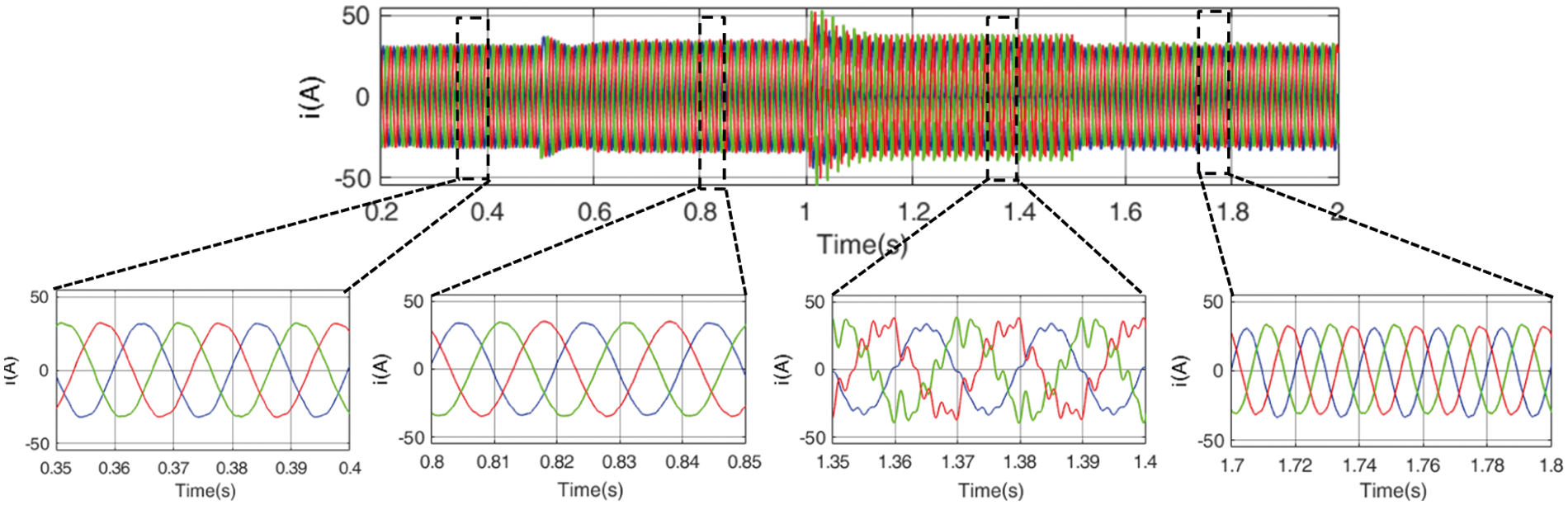
Figure 10: Common VSG control balanced current under unbalanced voltage
When the A-phase voltage amplitude drops to 240 V, the common VSG control balanced current under unbalanced voltage can still maintain the current balance, and the current amplitude is 34.3 A. When the grid voltage contains harmonics, the output current of common VSG control balanced current under unbalanced voltage will contain harmonics. The harmonic distribution of the three-phase current is shown in Fig. 11, and the harmonic distribution of the phase A, phase B, and phase C is from left to right.
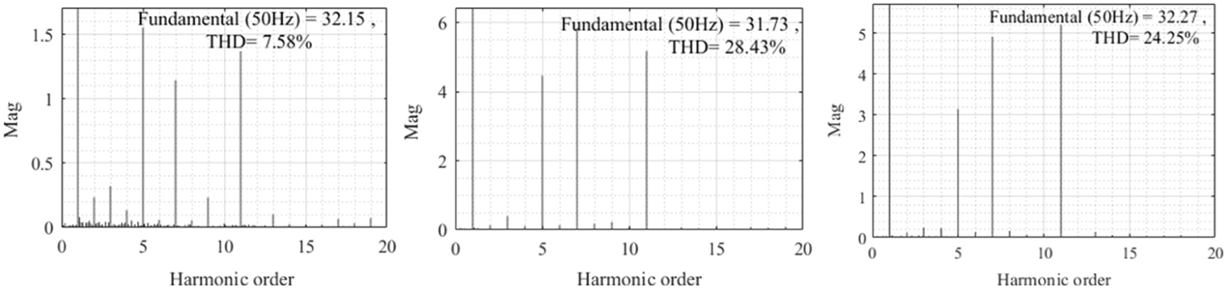
Figure 11: Harmonic distribution of three-phase current controlled by common VSG in power grid with harmonics
It can be seen from Fig. 11 that the harmonic content of common VSG control balanced current under unbalanced voltage-controlled three-phase current exceeds the allowable range of grid connection, and the voltage harmonic of phase B reaches 28.43%.
When the grid voltage contains a small amount of DC component, it can be seen from Fig. 10 that the three-phase current will be unbalanced, and the degree of imbalance is 23.3%, which seriously affects the power quality.
Under the same simulation conditions, the output three-phase current waveform of the proposed VSG control strategy under complex conditions is shown in Fig. 12.
It can be seen from Fig. 12 that the VSG control strategy under complex conditions can well control the three-phase balance of output current when the grid voltage is normal, unbalanced, with harmonic and DC components. When the grid voltage contains DC components, the unbalance degree is 1.4%, which is 93.9% lower than the VSG control strategy under ordinary unbalanced voltage.
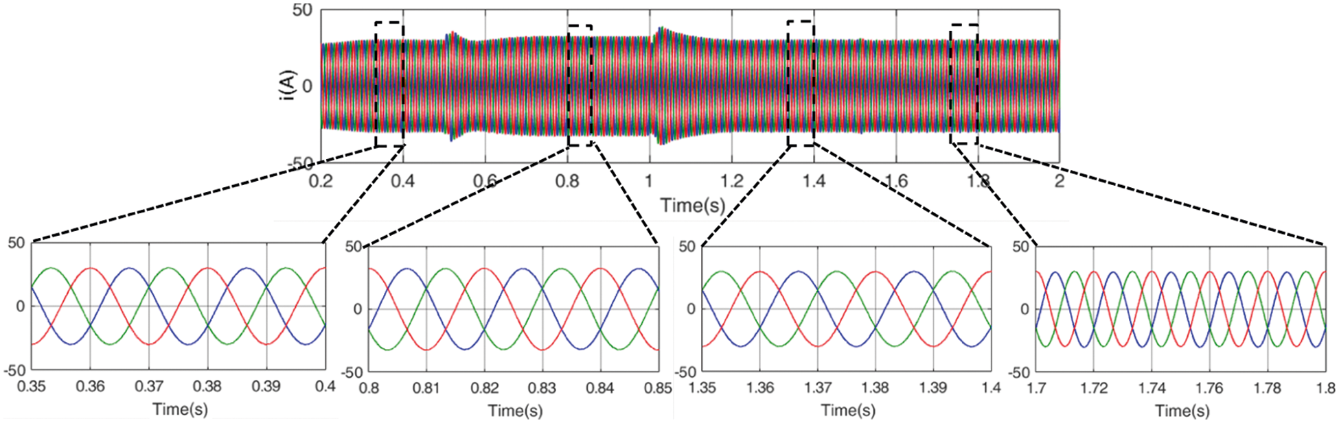
Figure 12: VSG control balance current under complex grid conditions
The harmonic distribution of VSG control strategy under complex conditions is shown in Fig. 13, and the harmonic distribution of phase A, phase B and phase C is in turn from left to right.
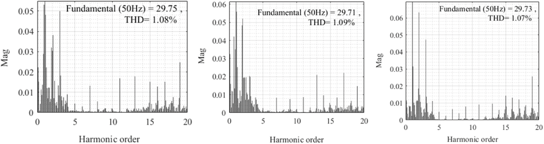
Figure 13: Harmonic distribution of VSG control current under complex conditions with harmonics in the power grid
According to the harmonic distribution diagram 13, the output current harmonics can be completely suppressed by the VSG control strategy under complex conditions when the grid voltage has harmonics. The current THD of phase A, phase B, and phase C is reduced from 7.58% to 1.08%, 28.43% to 1.09%, and 24.25% to 1.07%, respectively. The harmonic content is greatly reduced to meet the requirements of the grid-connected harmonic content standard.
Under the current balance control target, the power waveforms of the traditional balance current control strategy and the comprehensive control strategy under complex conditions are shown in Fig. 14.
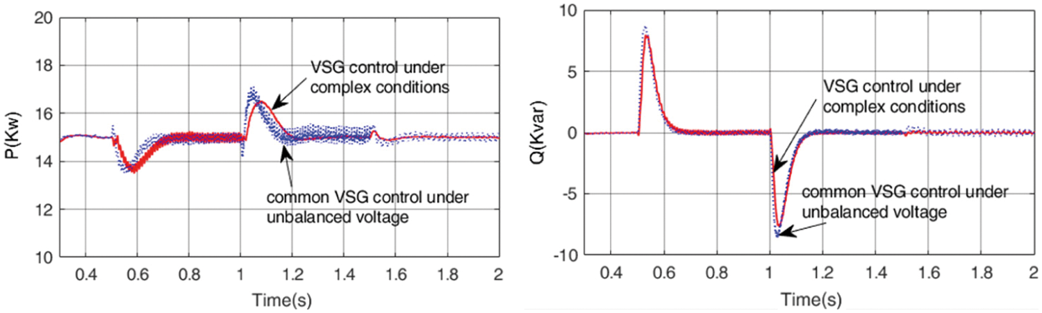
Figure 14: Power waveform under current balance control target
It can be seen from Fig. 14 that under normal grid voltage and three-phase unbalanced conditions, the power control of traditional common VSG control balanced current under unbalanced voltage and VSG control strategy under complex conditions are the same. However, when there are harmonics and DC components, the power of traditional VSG control under unbalanced voltage fluctuates. In contrast, VSG control under complex conditions can control constant power.
Under the same simulation conditions as the current balance control objective, the proposed scheme is verified with the a constant active power control objective.
Fig. 15 shows the current, active, and reactive power waveforms controlled by VSG under constant active power and complex working conditions.
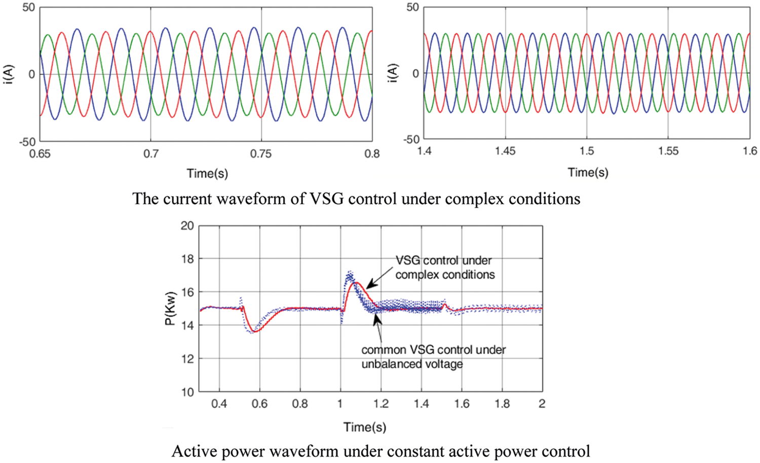
Figure 15: VSG control under complex conditions with constant active power
According to Fig. 15, under the active power constant control target, when the grid voltage is unbalanced, the three-phase current will be unbalanced as that of common VSG control balanced current under unbalanced voltage. However, for the grid voltage containing harmonic and micro-DC components, the proposed strategy can establish that the output current meets the grid connection requirements and the active power is constant. But the active power still fluctuates under common VSG control balanced current under unbalanced voltage.
Under the target of constant reactive power, the reactive power waveforms under the two control strategies are shown in Fig. 16.
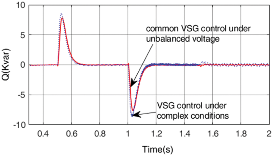
Figure 16: Power waveform under constant reactive power control target
It can be seen from Fig. 16 that under the target of constant reactive power and, the common VSG control under unbalanced voltage has fluctuation in reactive power when the grid voltage contains harmonic and trace DC content.
In this paper, VSG control strategy is proposed in the complex condition to realize grid-connected current to meet the grid connection requirements under complex voltage conditions, in the case of unbalanced three-phase voltage, harmonic and small DC components. The harmonic current is controlled by using TOGI to eliminate DC components, improve DSC and QPR cascade pi to control harmonic current. The harmonic content and unbalance degree meet the grid connection standard when grid-connected current balance is used for control purposes under the non-ideal grid voltage. Compared with the common VSG control balanced current under unbalanced voltage, VSG control under complex conditions can be applied in the multi-operation condition of power grid voltage. Finally, the control strategy can still achieve the control target under the condition that the power is constant for the control purpose.
Funding Statement: This work was funded by the National Natural Science Foundation of China (61863023).
Conflicts of Interest: The authors declare that they have no conflicts of interest to report regarding the present study.
1. Qi, W., Li, Y., Fang, F., Ding, L. (2019). Research on VSG grid-controlled strategy based on energy-storaged quasi-Z-source inverter. Power System Protection and Control, 47(4), 124–133. DOI 10.7667/PSPC180337. [Google Scholar] [CrossRef]
2. Bevrani, H., Ise, T., Miura, Y. (2014). Virtual synchronous generators: A survey and new perspectives. International Journal of Electrical Power & Energy Systems, 54, 244–254. DOI 10.1016/j.ijepes.2013.07.009. [Google Scholar] [CrossRef]
3. Shi, K., Ye, H., Song, W., Zhou, G. (2018). Virtual inertia control strategy in microgrid based on virtual synchronous generator technology. IEEE Access, 6, 27949–27957. DOI 10.1109/ACCESS.2018.2839737. [Google Scholar] [CrossRef]
4. Zhang, J., Wang, N., Huang, R., Ma, M., He, S. (2019). Survey on frequency regulation technology of power grid by high-penetration photovoltaic. Power System Protection and Control, 47(15), 179–186. DOI 10.19783/j.cnki.pspc.181042. [Google Scholar] [CrossRef]
5. Zhang, F., Piao, Z., Guo, Y., Zhang, X., Zhou, J. (2020). Research on adaptive control VSG rotation inertia. Acta Energiae Solaris Sinica, 41(10), 93–100. [Google Scholar]
6. Liu, J., Yang, D., Yao, W., Fang, R., Zhao, H. et al. (2017). PV-Based virtual synchronous generator with variable inertia to enhance power system transient stability utilizing the energy storage system. Protection and Control of Modern Power Systems, 2(1), 1–8. DOI 10.1186/s41601-017-0070-0. [Google Scholar] [CrossRef]
7. Yang, Y., Mei, F., Zhang, C., Miao, H., Chen, H. et al. (2019). Coordinated adaptive control strategy of rotational inertia and damping coefficient for virtual synchronous generator. Electric Power Automation Equipment, 39(3), 125–131. DOI 10.16081/j.issn.1006-6047.2019.03.020. [Google Scholar] [CrossRef]
8. Wu, H., Ruan, X., Yang, D., Chen, X., Zhong, Q. et al. (2015). Modeling of the power loop and parameter design of virtual synchronous generators. Proceedings of the CSEE, 35(24), 6508–6518. DOI 10.13334/j.0258-8013.pcsee.2015.24.027. [Google Scholar] [CrossRef]
9. Liu, J., Miura, Y., Ise, T. (2016). Comparison of dynamic characteristics between virtual synchronous generator and droop control in inverter-based distributed generators. IEEE Transactions on Power Electronics, 31(5), 3600–3611. DOI 10.1109/TPEL.2015.2465852. [Google Scholar] [CrossRef]
10. Cheema, K. M., Milyani, A. H., El-Sherbeeny, M. A., El-Meligy, M. A. (2021). Modification in active power-frequency loop of virtual synchronous generator to improve the transient stability. International Journal of Electrical Power & Energy Systems, 128, 106668. DOI 10.1016/j.ijepes.2020.106668. [Google Scholar] [CrossRef]
11. Cheema, K. M., Mahmood, R. S., Tahir, M. F., Mehmood, K., Javed, M. Y. et al. (2021). Modified control of virtual synchronous generator for microgrid stability improvement. 2021 International Bhurban Conference on Applied Sciences and Technologies (IBCAST). DOI 10.1109/IBCAST51254.2021.9393174. [Google Scholar] [CrossRef]
12. Geng, Y., Tian, F., Sun, S., Wei, C., Zhang, Y. (2018). A method of current harmonics suppression based on VSG. Transactions of China Electrotechnical Society, 33(5), 1040–1050. DOI 10.19595/j.cnki.1000-6753.tces.170093. [Google Scholar] [CrossRef]
13. Alipoor, J., Miura, Y., Ise, T. (2014). Voltage sag ride-through performance of virtual synchronous generator. Power Electronics Conference, pp. 3298–3305. Hiroshima, Japan. DOI 10.1109/IPEC.2014.6870160. [Google Scholar] [CrossRef]
14. Li, Z., Zhang, Z., Liu, H., Song, P., He, T. et al. (2020). Harmonic resonance characteristics analysis and suppression strategy of LCL energy storage virtual synchronous generator. Acta Energiae Solaris Sinica, 41(10), 101–108. [Google Scholar]
15. Wan, X., Hu, H., Nie, X., Yu, Y., Zeng, F. (2017). An improved control strategy for virtual synchronous generator under unbalanced grid voltage. Power System Technology, 41(11), 3573–3581. DOI 10.13335/j.1000-3673.pst.2016.3212. [Google Scholar] [CrossRef]
16. Yang, M., Gao, L., Wang, H., Du, S., Li, B. (2019). Coordinate control of power and current for virtual synchronous generator under unbalanced grid voltage. Power System Protection and Control, 47(6), 17–23. DOI 10.7667/PSPC180392. [Google Scholar] [CrossRef]
17. Hu, H., Wan, X., Ding, X., Yu, Y. (2020). Improved low voltage ride-through control strategy for distributed virtual synchronous generator. Electric Machines and Control, 24(1), 145–155. DOI 10.15938/j.emc.2020.01.018. [Google Scholar] [CrossRef]
18. Luo, D., Chen, Z., Huang, S., Guo, D. (2013). A novel field-weakening control strategy for interior permanent magnet synchronous motor. Journal of Hunan University (Natural Sciences), 40(3), 59–64. DOI 10.3969/j.issn.1674-2974.2013.03.011. [Google Scholar] [CrossRef]
19. Xiao, X., Chen, M. (2017). Power control of virtual synchronous generator under unbalanced grid voltage. Electric Power Automation Equipment, 37(8), 193–200. DOI 10.16081/j.issn.1006-6047.2017.08.026. [Google Scholar] [CrossRef]
20. Xie, J., Xie, Z., Lin, M. (2020). Control strategy of current balance based on VSG of DFIG under unbalanced grid voltage conditions. 39th Chinese Control Conference, pp. 5293–5298. Shenyang, China. DOI 10.23919/CCC50068.2020.9189131. [Google Scholar] [CrossRef]
21. Shi, K., Song, W., Xu, O., Liu, R., Fang, Z. et al. (2017). Low-voltage ride-through control strategy for a virtual synchronous generator based on smooth switching. IEEE Access, 6, 2703–2711. DOI 10.1109/ACCESS.2017.2784846. [Google Scholar] [CrossRef]
22. Chen, T., Chen, L., Wang, Y., Zheng, Y., Mei, S. (2016). Balanced current control of virtual synchronous generator considering unbalanced grid voltage. Power System Technology, 40(3), 904–909. DOI 10.13335/j.1000-3673.pst.2016.03.035. [Google Scholar] [CrossRef]
23. Feng, W., Sun, K., Guan, Y., Guerrero, J., Xiao, X. (2018). An active harmonic grid-connecting current suppression strategy for hierarchical control based microgrid. Transactions of China Electrotechnical Society, 33(6), 1400–1409. DOI 10.19595/j.cnki.1000-6753.tces.l70691. [Google Scholar] [CrossRef]
24. Hui, N., Wang, D., Li, Y. (2018). DC-Offset elimination method for grid-connected phase-Locked Loop by modified DSC. Journal of Northeastern University (Natural Science), 39(11), 1526–1531. DOI 10.12068/j.issn.1005-3026.2018.11.002. [Google Scholar] [CrossRef]
 | This work is licensed under a Creative Commons Attribution 4.0 International License, which permits unrestricted use, distribution, and reproduction in any medium, provided the original work is properly cited. |