| Energy Engineering |
DOI: 10.32604/ee.2022.019331
ARTICLE
Numerical Study on Heat Transfer Characteristic of the Plate-Fin Microchannel Heat Sink for Water-Based Thermal Management of CPU Chip
Guangdong Provincial Key Laboratory of Distributed Energy Systems, Guangdong Provincial Engineering Research Center of Distributed Energy Systems, Dongguan University of Technology, Dongguan, 523808, China
*Corresponding Author: Nan-Long Hong. Email: hongnl@dgut.edu.cn
Received: 17 September 2021; Accepted: 16 November 2021
Abstract: For effective water-based thermal management of high heat generating CPU chip, a series of numerical simulation has been conducted to study the effects of heat flux, fin height and flow rate on convective thermal performance of the plate-fin microchannel heat sinks. The characteristics of heat transfer and flow resistance have been quantificationally discussed and JF factor is employed to evaluate the comprehensive efficiency of convective heat transfer of microchannel heat sink. Results show that the increase in fin height and flow rate of cooling water is helpful to decrease the maximum temperature of CPU chip. Large flow rate and heat flux and short fin height are benefit to improve Nusselt number Nu, but they lead to large resistance coefficient fRe simultaneously. Analysis of JF factor shows that the microchannel with short fins shows better convective thermal performance when the thermal power of the CPU chip is small. The fins should be heightened when the CPU is operating at higher thermal power. The employment of JF factor in the present work shows its pertinence and convenience in the application of design of microchannel heat sink.
Keywords: JF factor; convective thermal performance; numerical simulation; thermal management of CPU
In recent years, the progress of computer technology constantly has pushed urgent requirements for the update of high performance chips, which resulting in a dramatic increase in the number of transistors inside a CPU [1,2]. In the design of the computing system, the cooling ability of chip becomes more and more important. At present, the mainstream commercial CPU chip power is up to 125 W. Traditional thermal management methods for CPU cannot be appropriate for such high heat flux. The limit of fan-fin cooling techniques is 50 W/cm2 due to fin efficiency and heat spreading bottlenecks. There are disproportionately large increases in pressure drop and acoustic noise with modest gains in heat transfer. Therefore, it will not be a valid solution [3]. One of the solutions proposed is to further enhance the heat transfer by utilizing microchannel heat sink in a liquid-based system since its high heat dissipation performance [4,5]. Liquid based cooling heat sink affords reasonable heat transfer coefficients in dealing with the heat dissipation problem of chips. The heat is extracted from the board by one heat sink and released to the air by another remote heat sink. It is accepted that the form factor constraints of liquid based cooling are not as severe [6,7].
Over the past 20 years, previous studies have shown that the water-based microchannel heat sink has high heat transfer surface areas per unit volume. However, its drawback is undesirable temperature gradients from inlet to outlet caused by the mono-directional fluid flow. Therefore, the layout of microchannel of the heat sink is very important for the thermal management design [8]. Numerous researchers have performed investigations on the optimal performance of water-based microchannel heat sink. By reducing the hydraulic diameter and changing the geometrical factors, including cross-sectional shape, pattern, manifold and input/output ports, optimization of average temperature, pressure drop, heat transfer coefficient, Nusselt number, as well as flow and temperature uniformity have been achieved [9]. Toh et al. [10,11] respectively conducted the numerical and experimental studies on the fluid flow and heat transfer in four kinds of straight microchannel. Results show that the temperature of the water increases, leading to a decrease in the viscosity and hence smaller frictional losses, particularly at lower Reynolds numbers. Ying et al. [12] numerically investigated the heat transfer performance of microchannel heat sinks with a length of 40 mm and different cross-sectional dimensions. The result shows rectangle structures have smaller pressure drop but higher heat transfer efficiency compared with the triangle and trapezoid shapes. Xie et al. [13] numerically investigated straight and rectangular microchannel heat sinks with different length bifurcation and dimension. Results show that proper design of the multiple length bifurcation could be employed to improve the overall thermal performance of microchannel heat sinks. Liang et al. [14] proposed to enhance heat transfer by equipping pin-fins in the channel walls of microchannel. However, the fluidity of the fluid flow is reduced. Therefore, in the design of microchannel heat sink, it is required to consider thermo-hydraulic performance, and fabrication capability [9], which means a balance between heat transfer enhancement and pressure drop penalty.
There are some parameters such as Performance Evaluation Criteria (PEC) which could be useful to specify crucial parameters [15,16]. Performance evaluation criteria (PEC) is calculated by using extracted data to achieve better decision from the perspective of cross-section and pattern of the microchannel heat sink. Liu et al. [17] proposed a novel microchannel sink with perforated baffles and perforated walls (MSPBPW) to ameliorate the bottom surface temperature of the heat sink. It is found that the heat transfer ability of MSPBPW with pressure drop penalty can be significantly improved, and the thermal performance evaluation criterion value is always greater than unity. Mazloumi et al. [18] evaluated the hydrothermal performance between plate fins and plate-pin fins subject to nanofluid-cooled corrugated miniature heat sinks. The maximum hydrothermal performance factor of 1.84 is detected for 0.3% nanofluid flow in the corrugated miniature heat sink with sinusoidal plate-pin fins. Additionally, it is noted that the JF factor is an important and common parameter in the application of the evaluation criteria for the overall thermal performance of different heat exchangers [19–21]. The JF factor can not only provide quantitative comparison of the simultaneous effect of heat transfer and friction, but also help to determine the key influence parameters of the research object.
The objective of the present study is to utilize the evaluation criteria JF factor to analyze the hydrothermal performance of the microchannel heat sink with straight fins. A series of numerical investigations on the velocity field and distributions of temperature and pressure for the water-based microchannel heat sink with various fin height, flow rate and CPU power have been carefully conducted. The present work aims to provide data reference for the design and optimization on configuration of microchannel heat sink.
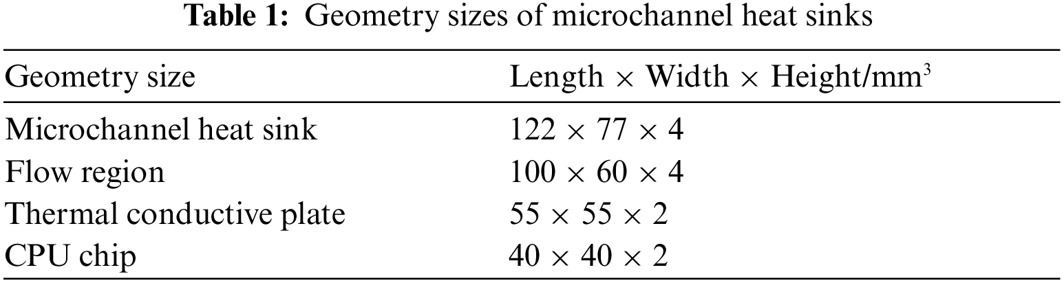
As shown in Fig. 1, the water-based microchannel heat sink with an array of straight fins was constructed [22]. Accordingly, the size difference between the CPU chip (I) and microchannel heat sink (III) is large. It is necessary to set a thermal conductive plate (II) between CPU chip and heat sink for the purpose to reduce the thermal resistance. The water inlet and water outlet are respectively set in the lower left corner and the upper right corner of the heat sink. The inner diameters of the inlet and outlet vents are both 5 mm. The width of each micro channel is 0.9 mm. The convective water extracts the heat from the board of the microchannels and released to the air by another remote heat sink, which results in the cooling effect on the CPU chip. The working fluid is pure water. Its detail thermodynamic properties are as follows: λ = 0.6 W/(m·K), μ = 0.001003 kg/(m·s), ρ = 998.2 kg/m3, cp = 4182 J/(kg·K), where λ, μ, ρ and cp refer to thermal conductivity, viscosity, density and specific heat, respectively. The microchannel is made of copper, with cp = 385 J/(kg·K), ρ = 8960 kg/m3 and λ = 400 W/(m·K). At the inlet vent, the temperature of cooling water flow is 293.15 K. The specific parameters of the straight-fin microchannel heat sink are shown in Table 1.
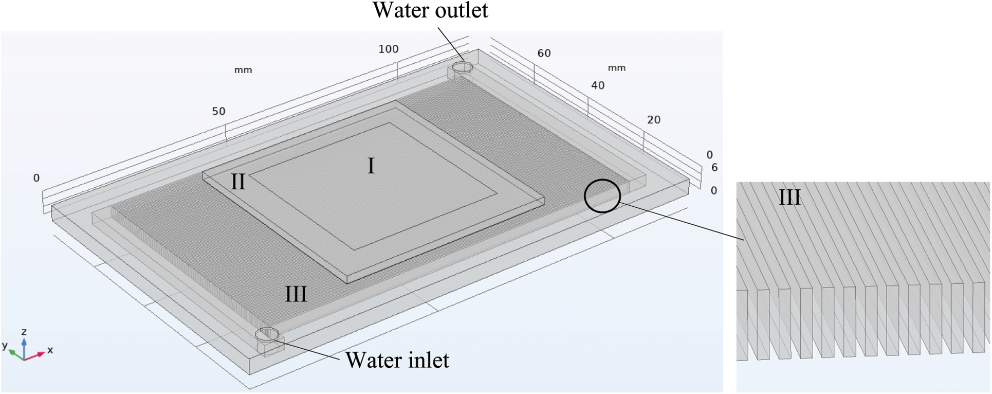
Figure 1: Geometric model of straight-fin microchannel heat sink. (I: bottom face of CPU chip, II: thermal conductive plate, III: microchannel heat sink)
In order to simplification, several assumptions were employed. (1) The Reynolds number in the channel bellows 1600 and the fluid flow is laminar and steady flow; (2) Fluid is incompressible, Newtonian, and viscous; (3) There is no velocity-slip at the solid-liquid walls; (4) The density in the momentum equation is assumed to be constant, except that the density in the diffusion term varies with temperature [18–21].
Therefore, the steady-state governing equations for mass, momentum, and energy conservations adopted in the present work are given as follows [23]:
where u denotes the velocities in the three-dimensional coordination, μ, p and T are respectively the dynamic viscosity, pressure and temperature.
Additionally, the Reynolds number Re, the Nusselt number Nu, j factor and the resistance coefficient f are defined as [24]:
in which, uch, uin, Dh, h, Pr, pin and pout respectively refer to velocity in the micro channel, velocity at the inlet, equivalent diameter of the micro channels, convective heat transfer coefficient, the Prandtl number, pressure at the inlet and outlet.
Most of the boundary conditions of the present work are unified setting for the microchannel heat sink with different fin heights. The water flow is fully developed at the inlet vent. Constant heat fluxes are adopted at the top of CPU chip, all of other walls were treated as adiabatic [25].
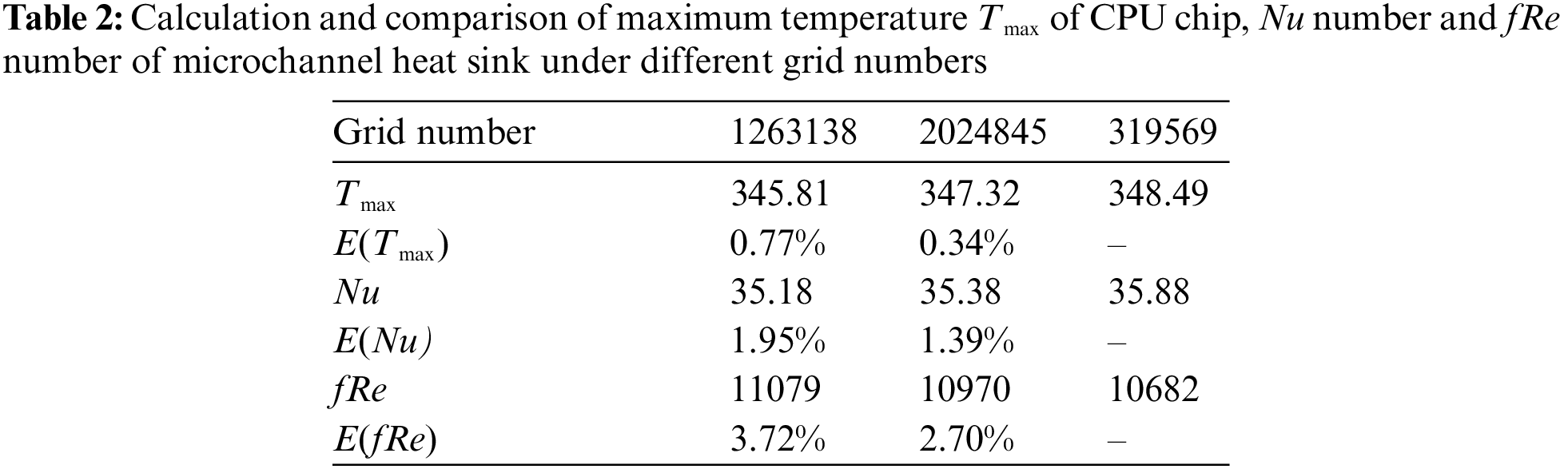
The software utilized to perform the present numerical simulation is COMSOL Multiphysics. The grid verification is performed by adopting the module with fin height of 2 mm, heat flux of 50 W/cm2 and inlet flow rate of 0.68 L/min. Hexahedral mapped mesh was adopted for the purpose of convergence speed and computing accuracy. Several meshes selected with grid numbers have been checked, as listed at Table 2. The calculated values Tmax, the mean Nusset number Nu and the mean flow resistance coefficient fRe with different mesh are compared. The relative errors such as E(Tmax), E(Nu) and E(fRe) at different meshes are within 5%. Considering the calculation time cost and accuracy, the selected grid number is 2024845.
In the present work, the microchannel heat sink modules are built with three fin heights Hf, i.e., 2 mm, 4 mm and 6 mm. The emitted heat fluxes qm from the bottom of CPU are 10 W/cm2, 20 W/cm2, 30 W/cm2, 40 W/cm2 and 50 W/cm2. The flow rates Vin of the cooling water are 0.21 L/min, 0.33 L/min, 0.45 L/min, 0.57 L/min and 0.68 L/min.
3.1 Heat Transfer Characteristics
In order to prevent the CPU operated at an overheated temperature, it is necessary to ensure that the maximum temperature Tmax of CPU is lower than the limited temperature Tlim (i.e., 348.15 K). The corresponding heat flux emitted from the CPU is called the limited heat flux.
As depicted in Fig. 2, the maximum temperature Tmax of CPU increases linearly with the heat flux qm, while it is inversely proportional to the flow rate Vin. it is obvious that the max temperature Tmax will exceed the limit temperature at large heat flux or small flow rate. For the fin height is Hf = 2 mm, the limited heat fluxes are about 32 W/cm2 and 40 W/cm2 when the flow rates are 0.21 L/min and 0.33 L/min. When the limited heat flux is 50 W/cm2, the flow rate reaches at 0.68 L/min. Moreover, the increase in fin height is helpful to improve the limiting heat flux. When the flow rate is fixed at 0.33 L/min, the limited heat flux is 40 W/cm2 at Hf = 2 mm, while the limited heat flux is about 50 W/cm2 at Hf = 4 mm and 6 mm.
Figs. 3a and 3b display the surface and inner temperature profiles of the microchannel heat sink when the fin height, flow rate and heat flux are respectively 4 mm, 0.33 L/min and 30 W/cm2. The temperature distribution of CPU chip is uneven. The part of the area with low temperature is near the inlet, while the high temperature zone locates at the opposite side. The temperature difference of the whole heat sink reaches 33 K.
Fig. 4 indicates the Nusselt number Nu is in positive proportion to the flow rate Vin and the heat flux qm. It implies that the increase of flow rate and heat flux is beneficial to the improvement in heat transfer capacity of the microchannel heat sink. Moreover, both the magnitude and increment of the Nu number at Hf = 2 mm are larger than those at Hf = 4 mm and Hf = 6 mm. For example, when the heat flux is qm = 10 W/cm2 the Nu number is 32~35 at Hf = 2 mm, while Nu number is 18~22 at Hf = 4 mm and 15~21 at Hf = 6 mm. Therefore, it is found that the microchannel heat sink with smaller fin height shows the better heat transfer capacity [22–27].
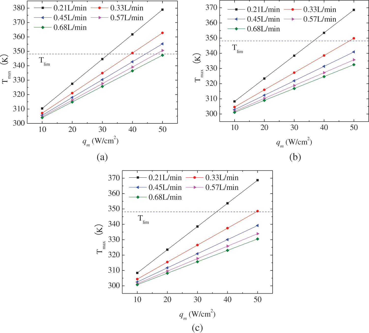
Figure 2: Variation of maximum temperature on the surface CPU chip with fin height of 2 mm (a), 4 mm (b) and 6 mm (c)
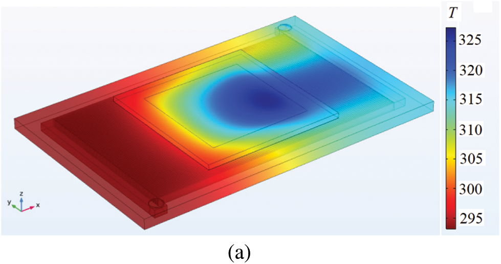
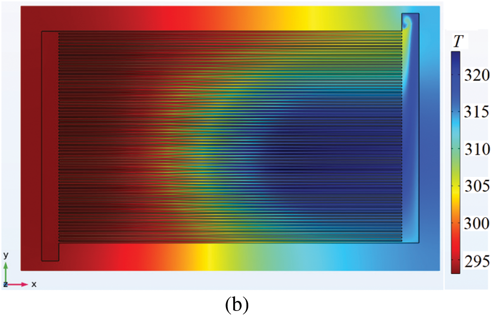
Figure 3: Temperature profiles of the whole microchannel heat sink (a) and the cross-section at z = 2 mm (b) when the fin height, flow rate and heat flux are respectively 4 mm, 0.33 L/min and 30 W/cm2

Figure 4: Variation of Nu number with the flow rate at fin heights of 2 mm (a), 4 mm (b) and 6 mm (c)
3.2 Flow Resistance Characteristics
The product of resistance coefficient and Reynolds number fRe is universal reference to reflect the corresponding flow losses for different types of heat sink [28,29]. As depicted in Fig. 5, the fRe value is almost linearly grows with the flow rate Vin at the considered fin heights and heat fluxes. When the fin height is 2 mm, the linear slops of the fRe to Vin are larger than those at Hf = 4 mm and at Hf = 6 mm. It is also found that the fRe values at Hf = 2 mm are about ten times larger than those at Hf = 6 mm. For instance, when Vin is 0.7 L/min and qm is 10 W/cm2, the fRe value is about 6.3 × 10⁴ at Hf = 2 mm, while the fRe values is about 6.0 × 10³ at Hf = 6 mm, respectively. Furthermore, the fRe value decreases with the heat flux. The increment of fRe with qm is also reduced with the increase of fin height.
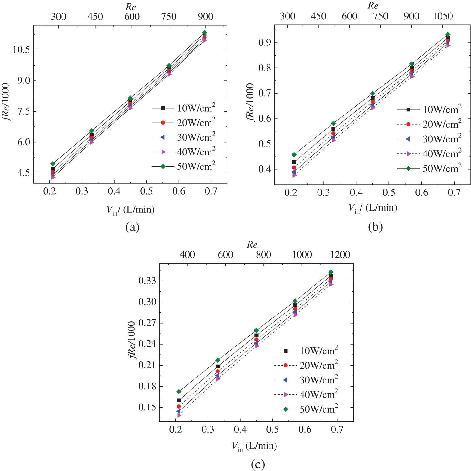
Figure 5: Variation of fRe with the flow rate Vin at fin height of Hf = 2 mm (a), 4 mm (b) and 6 mm (c)
3.3 Analysis on Convective Thermal Performance
JF factor [19–21,24] is the product of j factor and resistance coefficient f, which is utilized to evaluate the comprehensive efficiency of convective heat transfer and pressure drop in the microchannel heat sink. The JF factor is defined as:
where, the subscript R means the reference case. Obviously, the larger value of the JF factor denotes a better the convective thermal performance of the microchannel heat sink. Furthermore, the analysis on convective thermal performance in the present work is conducted among the cases that the maximum temperature Tmax of the CPU chip is less than the limited temperature.
Fig. 6 indicates the variation of JF factor with the flow rate and heat flux at different fin heights. When the fin height is Hf = 2 mm, the reference case is Vin = 0.21 L/min and qm = 10 W/cm2, hence the corresponding JF factor is fixed at 1. As shown in Fig. 6a, the JF factors are less than 1 for all the considered flow rate larger than 0.21 L/min, except for the two cases of qm = 20 W/cm2 and 30 W/cm2 at Vin = 0.21 L/min. The JF factor at different flow rate is monotonically increasing with the heat flux, however, it decreases with the flow rate. The values of JF factor at Vin = 0.68 L/min are less than 0.4 when Hf = 2 mm, which is resulted from the great flow resistance at large flow rates as shown in Fig. 5a. When the fin height increases, the number of operating case that Tmax is less than limited temperature increases at Vin = 0.33 L/min, as shown in Figs. 5b and 5c. Similarly, there are only two cases that the JF factor is larger than unit, i.e., qm = 20 W/cm2 and 30 W/cm2 at Vin = 0.21 L/min. Moreover, JF factor is proportional to the heat flux at Hf = 4 mm and Hf = 6 mm, while it is inversely proportional to the flow rate.
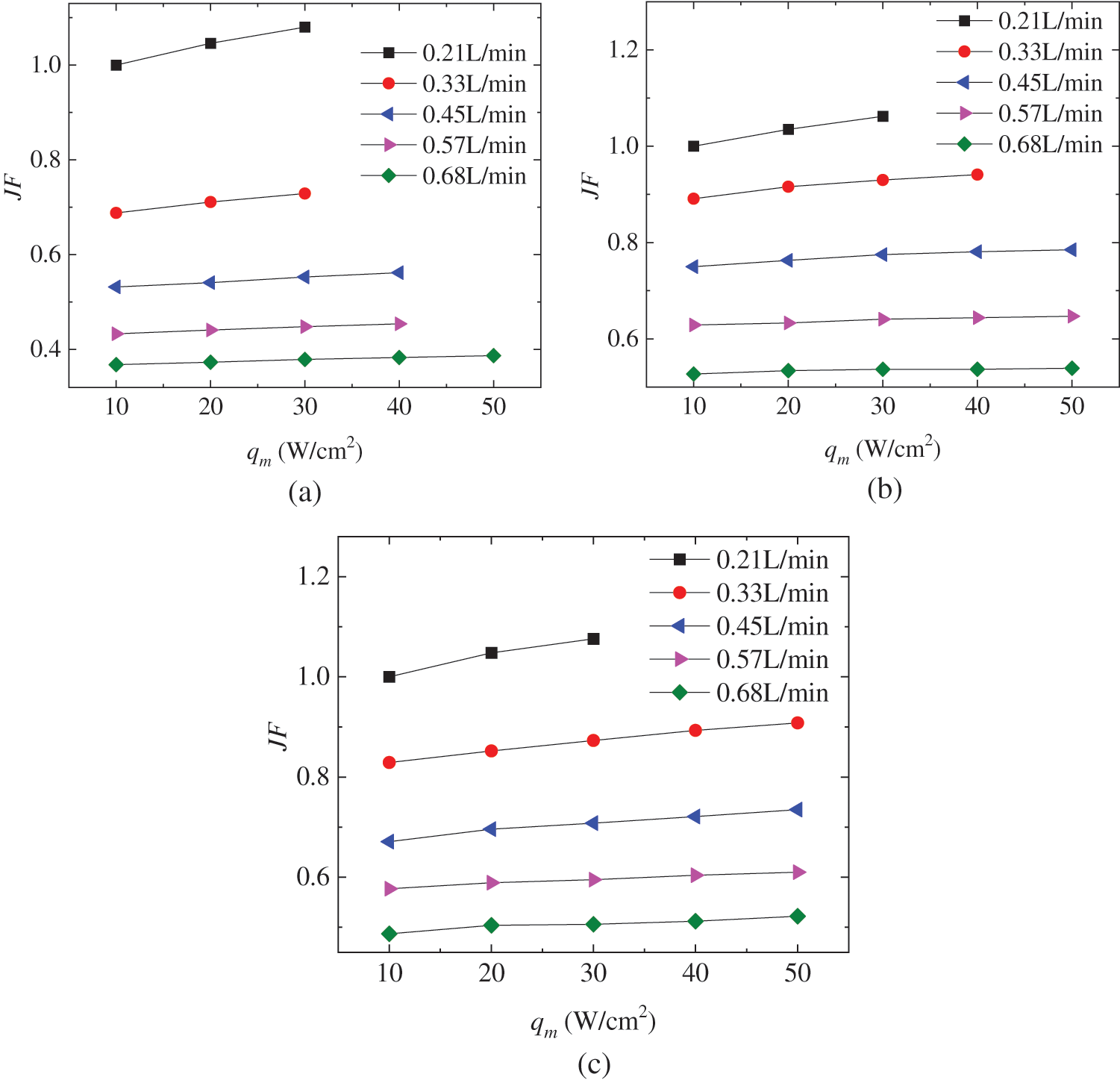
Figure 6: Variation of JF factor with the flow rate and heat flux at fin height of Hf = 2 mm (a), 4 mm (b) and 6 mm (c)
In order to determine the optimal operating case for the present, further evaluation has been conducted by selecting the best convective thermal performance at each heat flux within three fin heights. For instance, when the heat flux is 10 W/cm2, the best case is Vin = 0.21 L/min at three fin heights. When the heat flux is 50 W/cm2, the best cases are Vin = 0.68 L/min, 0.45 L/min and 0.33 L/min at Hf = 2 mm, 4 mm and 6 mm, respectively. As indicated in Fig. 7, the case at Hf = 4 mm is the reference case, hence the corresponding JF factor equals to 1. Results show that when the heat flux is less than or equal 30 W/cm2, the optimal operating case is at Vin = 0.21 L/min and Hf = 2 mm. When heat flux is 40 W/cm2 or 50 W/cm2, the optimal operating case is at Vin = 0.33 L/min and Hf = 6 mm. It implies that the microchannel with short fins shows optimal convective thermal performance when the thermal power of CPU chip is small. The fins should heighten when the CPU is operating at higher thermal power.
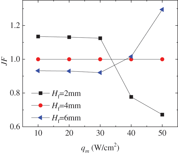
Figure 7: Comparison of JF factor among the selected case with best convective thermal performance at each heat flux within three fin heights
To reveal the effects of heat flux, fin height and flow rate on convective thermal performance of microchannel heat sinks, the fluid flow and heat transfer were numerically investigated and the JF factor were employed to evaluate the heat transfer characteristic. Main conclusions are given as follows:
1. The maximum temperature of CPU chip increases with the heat flux. The increase in fin height and flow rate of cooling water is helpful to improve the limiting heat flux of CPU.
2. Large flow rate and heat flux and short fin height are benefit to improve the Nusselt number in the microchannel heat sink, but it results in large resistance coefficient fRe simultaneously.
3. The JF factor increases monotonically with the heat flux, but decreases with the flow rate. When the heat flux is less than or equal 30 W/cm2, the optimal operating case is at Vin = 0.21 L/min and Hf = 2 mm. When heat flux is 40 W/cm2 or 50 W/cm2, the optimal operating case is at Vin = 0.33 L/min and Hf = 6 mm.
In general, the design of microchannel heat sink and the operating condition are very important to flow and heat transfer. The employment of JF factor shows its pertinence and convenience to evaluate the comprehensive convective thermal performance of microchannel heat sink.
Funding Statement: The work is supported by Doctoral Start-up Foundation of Dongguan University of Technology (GC300502-38), Guangdong Provincial Key Laboratory of Distributed Energy Systems (2020B1212060075), Natural Science Foundation of Guangdong Province (2019A1515110498, 2019A1515111167, 2021A1515110616) and Dongguan Institute of Technology quality Engineering (201802096).
Conflicts of Interest: The authors declare that they have no conflicts of interest to report regarding the present study.
1. Moore, G. E. (1998). Cramming more components onto integrated circuits. Electronics, 86(1), 82–85. DOI 10.1109/jproc.1998.658762. [Google Scholar] [CrossRef]
2. Nakayama, W. (1986). Thermal management of electronic equipment: A review of technology and research topics. Applied Mechanics Reviews, 39(12), 1847–1868. DOI 10.1115/1.3149515. [Google Scholar] [CrossRef]
3. Whelan, B. P., Kempers, R., Robinson, A. (2012). A liquid-based system for CPU cooling implementing a jet array impingement waterblock and a tube array remote heat exchanger. Applied Thermal Engineering, 39, 86–94. DOI 10.1016/j.applthermaleng.2012.01.013. [Google Scholar] [CrossRef]
4. Shahsavar, A., Shahmohammadi, M., Askari, I. B. (2003). CFD simulation of the impact of tip clearance on the hydrothermal performance and entropy generation of a water-cooled pin-fin heat sink. International Communications in Heat and Mass Transfer, 126, 105400. [Google Scholar]
5. Shen, H., Xie, G. N., Wang, X. X. (2020). Thermal performance and entropy generation of novel Xstructureddouble layered microchannel heat sinks. Journal of the Taiwan Institute of Chemical Engineers, 111, 90–104. [Google Scholar]
6. Arani, A. A. A., Akbari, O. A., Safaei, M. R., Marzban, A., Alrashed, A. et al. (2017). Heat transfer improvement of water/single-wall carbon nanotubes (SWCNT) nanofluid in a novel design of a truncated double-layered microchannel heat sink. International Journal of Heat and Mass Transfer, 113(9), 780–795. DOI 10.1016/j.ijheatmasstransfer.2017.05.089. [Google Scholar] [CrossRef]
7. Bare, P. A., Abubakar, S. B., Sidik, N. A. (2015). Numerical prediction of laminar nanofluid flow in rectangular microchannel heat sink. Journal of Advanced Research in Fluid Mechanics and Thermal Sciences, 7, 29–38. [Google Scholar]
8. Barrau, J., Chemisana, D., Rosell, J., Tadrist, L., Ibañez, M. (2010). An experimental study of a new hybrid jet impingement/micro-channel cooling scheme. Applied Thermal Engineering, 30(14), 2058–2066. DOI 10.1016/j.applthermaleng.2010.05.013. [Google Scholar] [CrossRef]
9. Alihosseini, Y., Targhi, M. Z., Heyhat, M. M., Ghorbani, N. (2020). Effect of a micro heat sink geometric design on thermo-hydraulic performance: A review. Applied Thermal Engineering, 170(4), 114974. DOI 10.1016/j.applthermaleng.2020.114974. [Google Scholar] [CrossRef]
10. Toh, K. C., Chen, X., Chai, J. (2002). Numerical computation of fluid flow and heat transfer in microchannels. International Journal of Heat and Mass Transfer, 45(26), 5133–5141. DOI 10.1016/S0017-9310(02)00223-5. [Google Scholar] [CrossRef]
11. Tuckerman, D. B. (1981). High-performance heat sinking for VLSI. IEEE Electron Device Letters, 2(5), 126–129. DOI 10.1109/EDL.1981.25367. [Google Scholar] [CrossRef]
12. Ying, H. E., Shao, B. D., Cheng, H. M. (2014). Numerical simulation and size optimization of rectangular micro-channel heat sinks. Applied Mathematics Mechanics, 35(3), 568–573. DOI 10.3879/j.issn.1000-0887.2014.03.006. [Google Scholar] [CrossRef]
13. Xie, G. N., Li, S. A., Sunden, B., Zhang, W. H. (2014). A numerical study of the thermal performance of microchannel heat sinks with multiple length bifurcation in laminar liquid flow. Numerical Heat Transfer, Part A: Applications, 65(2), 107–126. DOI 10.1080/10407782.2013.826084. [Google Scholar] [CrossRef]
14. Gong, L., Zhao, J., Huang, S. (2015). Numerical study on layout of micro-channel heat sink for thermal management of electronic devices. Applied Thermal Engineering, 88(3), 480–490. DOI 10.1016/j.applthermaleng.2014.09.048. [Google Scholar] [CrossRef]
15. Al-Neama, A. F., Kapur, N., Summers, J., Thompson, H. M. (2017). An experimental and numerical investigation of the use of liquid flow in serpentine microchannels for microelectronics cooling. Applied Thermal Engineering, 116(4), 709–723. DOI 10.1016/j.applthermaleng.2017.02.001. [Google Scholar] [CrossRef]
16. Khoshvaght-Aliabadi, M., Hassani, S. M., Mazloumi, S. H. (2017). Comparison of hydrothermal performance between plate fins and plate-pin fins subject to nanofluid-cooled corrugated miniature heat sinks. Microelectronics Reliability, 70(2), 84–96. DOI 10.1016/j.microrel.2017.01.005. [Google Scholar] [CrossRef]
17. Liu, H. L., Guo, H. Y., Xie, Z. L., Sang, L. (2021). Numerical investigations for optimizing a novel micro-channel sink with perforated baffles and perforated walls. International Communications in Heat and Mass Transfer, 126, 105342. DOI 10.1016/j.icheatmasstransfer.2021.105342. [Google Scholar] [CrossRef]
18. Mazloumi, H. S., Hassani, M. S., Khoshvaght-Aliabadi, M. (2017). Comparison of hydrothermal performance between plate fins and plate-pin fins subject to nanofluid-cooled corrugated miniature heat sinks. Microelectronics Reliability, 70(2), 84–96. DOI 10.1016/j.microrel.2017.01.005. [Google Scholar] [CrossRef]
19. Li, K., Wen, J., Yang, H., Wang, S., Li, Y. (2019). Sensitivity and stress analysis of serrated fin structure in plate-fin heat exchanger on cryogenic condition. International Journal of Thermal Sciences, 145(3), 106013. DOI 10.1016/j.ijthermalsci.2019.106013. [Google Scholar] [CrossRef]
20. Al-Zahrani, S., Islam, M. S., Saha, S. C. (2021). Comparison of flow resistance and port maldistribution between novel and conventional plate heat exchangers. International Communications in Heat and Mass Transfer, 123(9), 105200. DOI 10.1016/j.icheatmasstransfer.2021.105200. [Google Scholar] [CrossRef]
21. Mohebbi, S., Veysi, F. (2021). Numerical investigation of small plate heat exchangers performance having different surface profiles. Applied Thermal Engineering, 188(8), 116616. DOI 10.1016/j.applthermaleng.2021.116616. [Google Scholar] [CrossRef]
22. Zhao, Z., Li, L., Pu, Z., Ju, Z. (2015). Optimal design of water-cooled micro-channel radiator for chips. Refrigeration Air-Conditioning, 15(5), 32–37. [Google Scholar]
23. Toh, K. C., Chen, X. Y., Chai, J. C. (2002). Numerical computation of fluid flow and heat transfer in microchannels. International Journal of Heat and Mass Transfer, 45(26), 5133–5141. DOI 10.1016/S0017-9310(02)00223-5. [Google Scholar] [CrossRef]
24. Yun, J. Y., Lee, K. S., Wang, Y. H. (2000). Influence of design parameters on the heat transfer and flow friction characteristics of the heat exchanger with slit fins. International Journal of Heat and Mass Transfer, 43(14), 2529–2539. DOI 10.1016/S0017-9310(99)00342-7. [Google Scholar] [CrossRef]
25. Gong, L., Zhao, J., Huang, S. (2015). Numerical study on layout of micro-channel heat sink for thermal management of electronic devices. Applied Thermal Engineering, 88(3), 480–490. DOI 10.1016/j.applthermaleng.2014.09.048. [Google Scholar] [CrossRef]
26. Kwon, H., Joo, Y., Kim, S. J. (2018). Analytic approach to thermal optimization of horizontally oriented radial plate-fin heat sinks in natural convection. Energy Conversion and Management, 156, 555–567. DOI 10.1016/j.enconman.2017.11.076. [Google Scholar] [CrossRef]
27. Buyruk, E., Karabulut, K., Karabulut, Ö. O. (2013). Three-dimensional numerical investigation of heat transfer for plate fin heat exchangers. Heat and Mass Transfer, 49(6), 817–826. DOI 10.1007/s00231-013-1129-8. [Google Scholar] [CrossRef]
28. Ghani, I. A., Sidik, N., Kamaruzaman, N. (2017). Hydrothermal performance of microchannel heat sink: The effect of channel design. International Journal of Heat and Mass Transfer, 107, 21–44. DOI 10.1016/j.ijheatmasstransfer.2016.11.031. [Google Scholar] [CrossRef]
29. Zhou, J., Cao, X., Zhang, N., Yuan, Y., Zhao, X. et al. (2020). Micro-channel heat sink: A review. Journal of Thermal Science, 29(6), 1431–1462. DOI 10.1007/s11630-020-1334-y. [Google Scholar] [CrossRef]
 | This work is licensed under a Creative Commons Attribution 4.0 International License, which permits unrestricted use, distribution, and reproduction in any medium, provided the original work is properly cited. |