| Energy Engineering |
DOI: 10.32604/ee.2022.020488
ARTICLE
Case Analysis of a Pump-Driven Heat Pipe Heat Recovery Ventilator in an Existing Experiment Building
1Hefei Institutes of Physical Science, Chinese Academy of Sciences, Hefei, 230031, China
2University of Science and Technology of China, Hefei, 230026, China
3National Institute of Metrology, Beijing, 100029, China
*Corresponding Author: Zhun Li. Email: lizhun@nim.ac.cn
Received: 26 November 2021; Accepted: 24 February 2022
Abstract: The building energy consumption is an important part among the total society energy consumption, in which the energy consumption for air conditioning occupies almost 70%. The energy consumption of the air conditioning system for fresh air handling can be saved effectively when the exhaust air energy could be recovered to preheat or precool the fresh air. Considering the install locations requirements on field, the pump-driven heat pipes (PHP) were developed as heat recovery ventilators (HRVs) and used in an existing experiment building in Beijing Urban. The thermal performance of the PHP HRVs was tested in real operation time periods under winter running mode. Both the power and heat consumption of the modular air handling units with and without HRVs were monitored and obtained, as well as the hourly power and heat consumption. The energy savings of HRVs were analyzed. The results indicate that the PHP HRVs can work steadily and meet the energy recovery need well. The temperature effectiveness of the HRVs can be kept from 60% to 70%. The test total energy saving rate was 24.48%, and the average hourly heat consumption reduced by 28.54%. The daily energy consumption can be saved by 118 kWh, and the energy savings can reach to 9440 kWh for a whole winter.
Keywords: Case analysis; heat recovery ventilator; pump-driven heat pipe; temperature effectiveness; energy saving
Nomenclature
| E1 | Energy consumption before transform, kWh |
| E2 | Energy consumption after transform, kWh |
| r | Energy saving rate, % |
| T11 | Fresh air inlet temperature, °C |
| T12 | Fresh air outlet temperature, °C |
| T21 | Exhaust air inlet temperature, °C |
| Temperature effectiveness, % |
The building energy consumption and proportion in total energy consumption increase year by year with development of total civil buildings and living standard. The energy saving in building field plays an important role to carbon peak achievement. The fresh air handling energy consumption of air conditioners is the main source for building energy consumption, which occupies almost 70% of the building energy consumption. Buildings using exhaust and fresh air systems for 24 h/day could benefit from air-to-air heat recovery ventilators (HRVs). Such recovery devices can reduce energy consumption by transferring 40% to 80% of the sensible and latent heat between the exhaust air and fresh air streams [1]. The HRVs are applied widely in residential and commercial air conditioning systems nowadays. Air-to-air HRV using in fresh air system for room or building includes integral and separated types. The rotary thermal wheels [2], plate [3,4], plate-fin [5], heat pump [6] and integrated heat pipe [7–9] all belong to the integral type HRV. Both the intermediate working medium chiller and split heat pipe are separated type HRVs. O’Connor et al. [10] analyzed and compared six different HRVs in UK. Heat pipes and rotary thermal wheels were suggested as the mostly potential technologies due to high thermal efficiency and low pressure loss across the HRV in comparison to the other technologies [11]. However, fresh air cannot be isolated from exhaust air in the rotary thermal wheels, so fresh air may be contaminated by exhaust air although its energy recovery efficiency is high.
For the integral heat pipe owning high effectiveness, the fresh air and exhaust air ducts should be set up closely due to heat exchanger’s structure. When fresh air duct and exhaust air duct is apart or there are several fresh/exhaust air ducts, split heat pipe is available but integral heat pipe not. The split heat pipe is the development of conventional heat pipe, in which the low boiling-point substance is charged as working fluid for phase-change heat transfer assisted with capillary force or gravity. Chen et al. [12] investigated the rules between heat recovery effectiveness and indoor and outdoor temperature difference, and found that the split heat pipe needed to be started up under some suitable temperature difference. The minimum start-up temperature difference was still needed further study. Besides, the split heat pipe can only work while the condenser must be installed higher than the evaporator, and only runs in summer or in winter, not for a whole year. In addition, the weak driving force is another disadvantage of split heat pipe, especially for multi condensers and evaporators system. The pump-driven heat pipe (PHP) with strong driving force can eliminate both the installation limits and height difference requirements, and can recover energy for a whole year just by switching its running modes.
The investigations on PHP HRVs in buildings, especially for low temperature air to air heat exchanging, have been hardly indexed in publications. Zhou et al. [13,14] designed a PHP with strong driving force as a new HRV, which eliminated the installation and height difference requirements and could be used widely. The single-loop PHP as a HRV was developed, and the influences of working fluid, mass flow rate, heat exchanging area and facing air velocity were studied experimentally [13]. For exceeding the temperature effectiveness limit of the single-loop PHP, a triple-loop PHP as a HRV was developed and studied experimentally by changing flow path layout [14]. The uniformity of temperature difference distribution could be improved clearly with increasing loop number in winter conditions but not obviously in summer conditions. Bryan et al. [15] investigated the enhancement of the heat transport capacity of a mono groove heat pipe with electro-hydrodynamic (EHD) pumping. The EHD pump was located on the liquid channel in the adiabatic section of the heat pipe. The heat pipe fluid used in experiments was R123, and over 100% enhancement was achieved using the EHD pump operating at 20 kV. Anyhow, the present studies are mostly theoretical and experimental researches, and the application in a real project is still lacking, which is very important to technology application and promotion. In this paper, the PHP HRVs were designed and applied in an existing experiment building in Beijing Urban. The running status was monitored and operation data were obtained in winter conditions. The real operation energy savings of the case building were analyzed.
2.1 Case Existing Experiment Building
The case building is an existing building with two floors for calibration experiments in Beijing Urban, which lies in semi-moist continental warm temperate monsoon climate with four distinct seasons. It is dry and windy in spring, hot and rainy in summer, cool in autumn, cold and dry in winter. The annual average sunshine time is 2684 h, the annual average temperature is 11.8°C, and the annual average precipitation is 550.3 mm. Three modular air handling units (MAHUs) run for air conditioning of the test room. The dry-bulb temperature and relative humidity requirements are 20 ± 1°C and <70%, respectively. The specifications of three MAHUs were listed in Table 1 and the distribution diagram of the whole ventilating system was shown in Fig. 1.
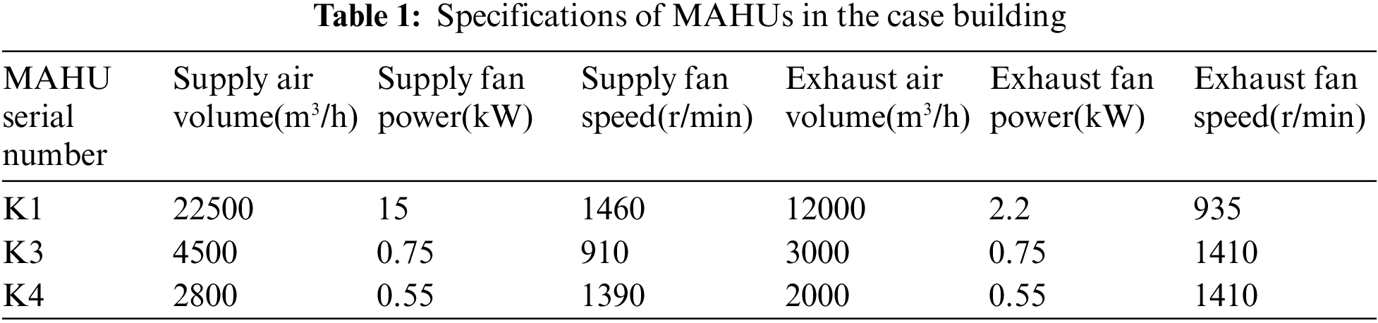
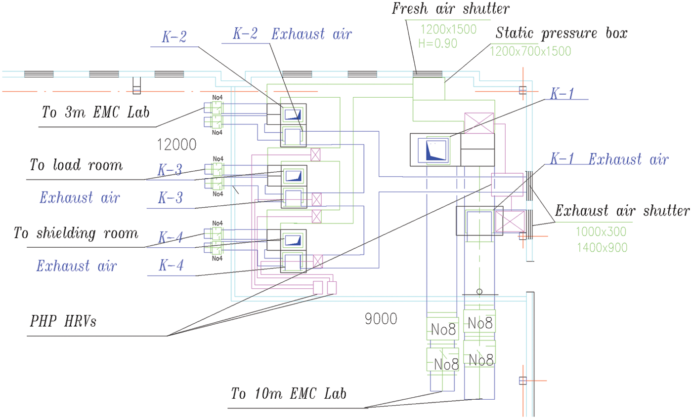
Figure 1: The distributions of the ventilating system in the case project
Thinking of the local policy and environmental requirements, for the case building the MAHUs work under the vapor compression refrigeration cycle to provide cool water in summer. In winter the electric boiler is used to produce hot water, which flows into the evaporators of the MAHUs to heat fresh air. Besides, the electric heating unit was an auxiliary in vent for fresh air heating. The MAHUs work for multiple rooms in different floor in daytimes (from 8:00 AM to 18:00 PM).
2.2 Pump-Driven Heat Pipe Heat Recovery Ventilator
For the MAHUs in the above case building, three PHP HRVs were developed and installed as shown in Fig. 2. The PHP HRV consisted of a refrigerant pump, fresh air heat exchanger, exhaust air heat exchanger, liquid reservoir and cut-off valves. The pump was a self-priming magnetic pump. The heat exchangers were fin-tube heat exchangers. The liquid reservoir could improve the system stability with decreasing the pressure pulse during system start-up. The low boiling-point refrigerant R32 was charged into the HRV after vacuuming. The fresh air heat exchanger was installed in the fresh air vent inlet and the exhaust air heat exchanger was installed in the exhaust air vent outlet. The other parts were set up in a cabinet. The PHP HRV was also equipped with test sensors and a controlling system. The PHP HRV could recover the heat/cold energy from exhaust air to preconditioning fresh air through refrigerant circulation, then the energy consumption for fresh air handling decreased. The circulation direction of the refrigerant would change through valves’ cut-off. Then the running modes for winter and summer could be transferred each other as shown in Fig. 3.
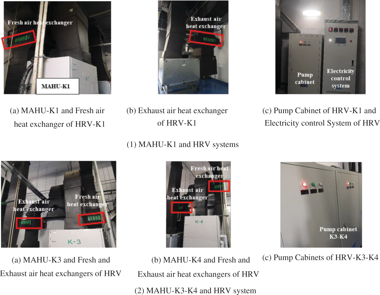
Figure 2: Onsite pictures of the PHP HRVs and MAHUs in the case building
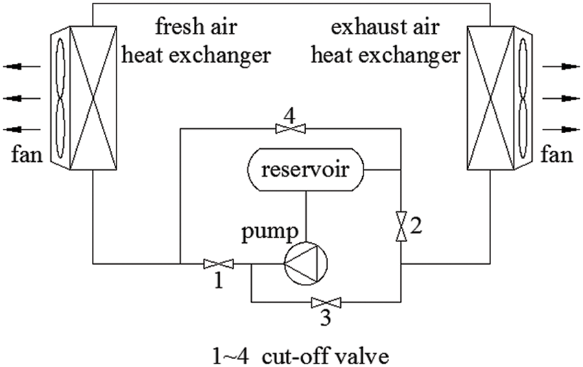
Figure 3: PHP HRV system flowchart in winter mode
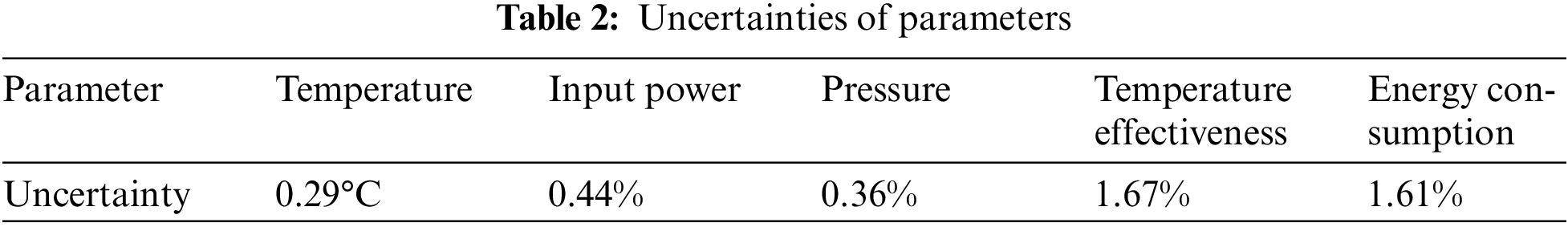
The following parameters were measured during tests: inlet and outlet fresh air temperatures, inlet exhaust air temperature, inlet and outlet pressures of liquid pump. The electricity meter for the air conditioning system including the HRV was read from the general power platform. The air temperature was gotten by Platinum resistance sensors (type PT100) and the test range of −30°C to 150°C connected to the control and data acquisition system. The interval of data acquisition was set as 1 min. The uncertainties were analyzed according to the standard deviation, and were calculated by the Class A evaluation method (statistical analysis method), and the results were listed in Table 2.
The performance of tested HRV was evaluated with temperature effectiveness ƞ and energy saving rate r. The equations were listed as follows:
The comparison tests were carried out in two days before and after according to the test plan. In the first test day, both the MAHUs and HRVs ran from 8:00 AM to 18:00 PM in 20th December, 2020. In the second test day, the MAHUs worked from 8:00 AM to 18:00 PM in 21st December, 2020, while the HRVs stopped in the same time. The power consumption and heat metering of the MAHUs with/without the HRVs were obtained through the independent energy consumption monitoring united platform. The dimension of heat metering data has been converted into kWh automatically by the platform. The data were acquired at 8:00, 11:00, 15:00 and 18:00, separately. And the record intervals were 3, 4 and 3 h, respectively. The operating pressure of the HRVs during tests remained in the range of 0.93 MPa to 1.64 MPa.
Fig. 4 showed the temperature effectiveness of the HRV system basing on tests results and Eq. (1). The temperature effectiveness firstly increased from 8:00 AM, then started decreasing at 11:30 AM. This results indicate that the temperature effectiveness varied with the fresh air temperature. According to Eq. (2), the fresh air inlet temperature, as well as the working temperature, is the key parameter to affect the refrigerant vapor condensation when the exhaust air inlet temperature is almost constant. This is consistent with the changes in reference [13]. The temperature effectiveness changed little after that in the afternoon. Generally, the temperature effectiveness of the HRV changed within the range of 60% to 70% at steady operations, but was lower than 60% during starting up. The average temperature effectiveness was about 65.7%. Besides, the average temperature effectiveness in the morning was higher than that in the afternoon.
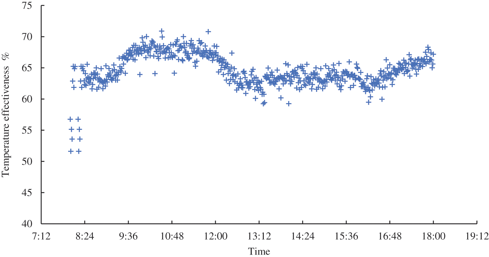
Figure 4: Operation temperature effectiveness of the HRV
4.2 Energy Consumption and Savings
The energy consumption of the MAHUs and HRVs includes two parts, power consumption and heat consumption. Both the power and heat consumption were obtained from the independent energy consumption monitoring united platform, and the results were shown in Figs. 5 and 6.
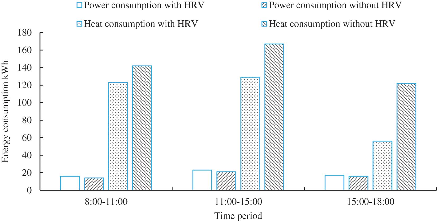
Figure 5: Power and heat consumption with/without HRV during test time periods
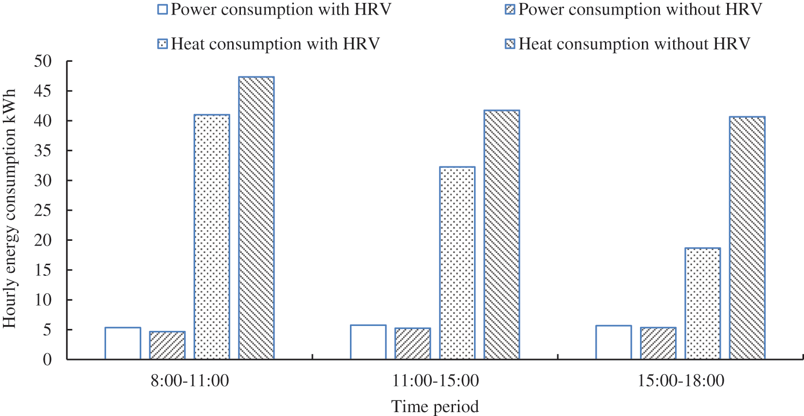
Figure 6: Hourly power and heat consumption with/without HRV during test time periods
As shown in Fig. 5, the heat consumption with the HRV was less than that without the HRV obviously for three different test periods. The reduction of heat consumption with and without the HRV increased during running time, which was 13.38%, 22.75% and 54.10%, separately. While the power consumption with the HRV was slightly more than that without the HRV in the same test periods. The growth of power consumption with and without the HRV decreased in test time periods, which was 14.29%, 9.52% and 6.25%, respectively. The average power saving rate and heat saving rate were −9.8% and 28.54%, and the total energy saving rate was 24.48%.
The power consumption with the HRVs is higher than that without the HRVs, which was caused by the specific test conditions. During winter mode tests, the MAHUs remained at stand-by state, the heat water from electricity boilers supplied the heating source through the heat exchangers of the MAHUs to keep the building required constant temperature. When the supply air temperature is over the set air temperature point, the MAHUs would work for cooling to remain the constant supply temperature instead of the standby condition. Then the power consumption with the HRVs got increased. Besides, the HRVs power consumption was also monitored in the united platform and included in total power consumption. The total power difference between with and without HRVs was 5 kWh for entire test time.
Considering the difference of test time periods, the hourly power consumption and heat consumption of the MAHUs with and without HRVs were also presented in Fig. 6. As shown in Fig. 6, the hourly power consumption varied a little no matter with or without HRVs. When the HRVs worked the average hourly power consumption was about 5.58 kWh, while that was 5.08 kWh if the HRVs stopped. The hourly power consumption difference (0.5 kWh) came from the MAHUs running occasionally and the HRVs running. The hourly heat consumption was saved clearly due to the HRVs. And both the hourly heat consumption with and without HRVs decreased during 8:00 to 18:00. The hourly heat consumption can be reduced by 13.38%, 22.75% and 54.10%, respectively, because of the HRVs in three test time periods. And the average reduction of hourly heat consumption brought by HRVs can reach about 28.54%.
4.3 Winter Mode Energy Savings Analysis
The above test daily results were adopted and expanded to analyze the annual energy savings according to the running modes and energy saving rate. The detail running time for different modes were listed in Table 3. The HRVs were assumed to work with the MAHUs in winter at the average energy saving rate 24.48% and the daily energy saving was the same as the test results. And the total energy savings in winter mode can be obtained as Table 4.

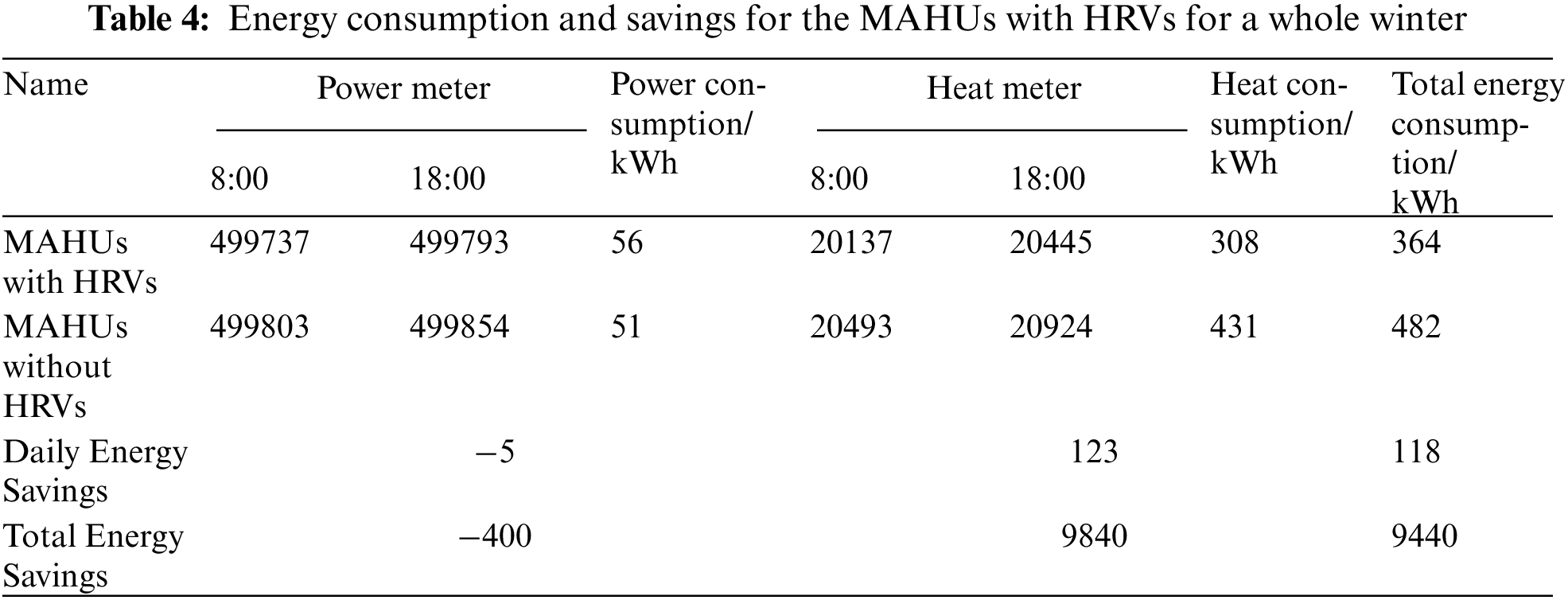
The daily heat consumption can be saved by 123 kWh and the daily power consumption would increase by 5 kWh, which indicates the net daily energy saving as 118 kWh as shown in Table 4. According to the test daily results, the total energy consumption in winter mode can be obtained basing on the running time in Table 3. Then for winter mode the total energy consumption could be reduced by 9440 kWh including power and heat consumption, which is 2539.36 kg coal equivalent.
The PHP HRVs were developed and installed in an existing experiment building to save the energy consumption of the MAHUs. The temperature effectiveness and energy savings were tested in real operations. The conclusions were drawn as follows:
(1) The PLHP HRVs can meet the need of energy recovery for the MAHUs, and the temperature effectiveness of the HRVs varied in the range of 60%--70% at steady condition. The average temperature effectiveness in the morning was higher than that in the afternoon.
(2) The PHP HRVs can reduce the heat consumption obviously but increase the power consumption due to cooling power consumption to remain constant supply temperature. The test total energy saving rate including power and heat reached 24.48%.
(3) The hourly power consumption changed slightly with or without the HRVs, while the hourly heat consumption got reduced by 28.54% on average due to the HRVs adoption.
(4) The daily energy consumption can be saved by 118 kWh and the total energy savings can reach 9440 kWh for a whole winter.
Funding Statement: This research was financially supported by the Project of Science and Technology Program of Beijing Municipal Chao Yang District (CYSF2005, Zhun Li, http://www.bjchy.gov.cn/dynamic/notice/8a24fe83722fa7180172360a3f46044c.html).
Conflicts of Interest: The authors declare that they have no conflicts of interest to report regarding the present study.
1. ASHRAE (2007). ASHRAE handbook—HVAC applications, A01 residences. 1.6. [Google Scholar]
2. Simonson, C. J., Ciepliski, D. L., Besant, R. W. (1999). Determining the performance of energy wheels: Part I-Experimental and numerical methods. ASHRAE Transactions: Research, 174–180. [Google Scholar]
3. Arsenyeva, O. P., Tovazhnyanskyy, L. L., Kapustenko, P. O., Khavin, G. L., Yuzbashyan, A. P. et al. (2016). Two types of welded plate heat exchangers for efficient heat recovery in industry. Applied Thermal Engineering, 105, 763–773. DOI 10.1016/j.applthermaleng.2016.03.064. [Google Scholar] [CrossRef]
4. Al-Waked, R., Mostafa, D. B., Nasif, M. S. (2021). Performance of energy recovery ventilators under different climatic regions. Energy Efficiency, 14(1), 37–58. DOI 10.1007/s12053-020-09917-w. [Google Scholar] [CrossRef]
5. Jiao, A. J., Li, Y. Z., Zhang, R. (2003). Effects of different distributor configuration parameters on fluid flow distribution in plate-fin heat exchanger. CIESC Journal, 54(2), 153–158. DOI 10.3321/j.issn:0438-1157.2003.02.004. [Google Scholar] [CrossRef]
6. Nguyen, A., Kim, Y., Shin, Y. (2005). Experimental study of sensible heat recovery of heat pump during heating and ventilation. International Journal of Refrigeration, 28, 242–252. DOI 10.1016/j.ijrefrig.2004.07.022. [Google Scholar] [CrossRef]
7. Zhou, F., Ma, G. Y. (2007). Experiment of characteristics of thermosiphon heat recovery equipment under summer condition. Journal of HV & AC, 37(12), 58–62. DOI 10.3969/j.issn.1002-8501.2007.12.013. [Google Scholar] [CrossRef]
8. Gedik, E., Yilmaz, M., Kurt, H. (2016). Experimental investigation on the thermal performance of heat recovery system with gravity assisted heat pipe charged with R134a and R410a. Applied Thermal Engineering, 99, 334–342. DOI 10.1016/j.applthermaleng.2015.12.075. [Google Scholar] [CrossRef]
9. Noie-Baghban, S. H., Majideian, G. R. (2000). Waste heat recovery using heat pipe heat exchanger (HPHE) for surgery rooms in hospitals. Applied Thermal Engineering, 20, 1271–1282. DOI 10.1016/S1359-4311(99)00092-7. [Google Scholar] [CrossRef]
10. O’Connor, D., Calautit, J. K. S., Hughes, B. (2016). A review of heat recovery technology for passive ventilation applications. Renewable & Sustainable Energy Reviews, 54, 1481–1493. DOI 10.1016/j.rser.2015.10.039. [Google Scholar] [CrossRef]
11. Liu, D., Tang, G. F., Zhao, F. Y. (2006). Modeling and experimental investigation of looped separate heat pipe as waste heat recovery facility. Applied Thermal Engineering, 26, 2433–2441. DOI 10.1016/j.applthermaleng.2006.02.012. [Google Scholar] [CrossRef]
12. Chen, F. S., Chen, D. (2002). Technical and economic analysis of heat circuit application to the spray drying equipment. Energy Conservation Technology, 20(2), 35–36. DOI 10.3969/j.issn.1002-6339.2002.02.015. [Google Scholar] [CrossRef]
13. Zhou, F., Duan, W., Ma, G. Y. (2017). Thermal performance of a pump-driven loop heat pipe as an air-to-air energy recovery device. Energy and Buildings, 151, 206–216. DOI 10.1016/j.enbuild.2017.06.057. [Google Scholar] [CrossRef]
14. Zhou, F., Duan, W., Ma, G. Y. (2018). Thermal performance of a multi-loop pump-driven heat pipe as an energy recovery ventilator for buildings. Applied Thermal Engineering, 138, 648–656. DOI 10.1016/j.applthermaleng.2018.04.104. [Google Scholar] [CrossRef]
15. Bryan, J. E., Seyed-Yagoobi, J. (1997). Heat transport enhancement of mono groove heat pipe with electro-hydrodynamic pumping. Journal of Thermophysics and Heat Transfer, 11(3), 454–460. DOI 10.2514/2.6261. [Google Scholar] [CrossRef]
 | This work is licensed under a Creative Commons Attribution 4.0 International License, which permits unrestricted use, distribution, and reproduction in any medium, provided the original work is properly cited. |