| Energy Engineering |
DOI: 10.32604/ee.2022.021070
ARTICLE
Soot Distribution and Thermal Regeneration of Marine Diesel Particulate Filter
1School of Electrical Engineering, Nantong University, Nantong, 226019, China
2School of Mechanical Engineering, Nantong University, Nantong, 226019, China
*Corresponding Author: Peiyong Ni. Email: nipeiyong@ntu.edu.cn
Received: 25 December 2021; Accepted: 18 February 2022
Abstract: Diesel particulate filter (DPF) is a leading technology reducing particle emissions from marine diesel engines. The removal or regeneration of soot in DPF is an important issue. The purpose of this study is to provide some reference strategies to design the DPF for marine diesel engines. In this paper, a mathematical model of a marine DPF was built up and the particle trap process and the regeneration dynamics were simulated. The results show that the cake soot mass concentrations from 0 to 4.2 g/L during the trap process increase linearly with the increase of the exhaust gas flows while the depth soot mass concentrations from 0 to 2.2 g/L firstly increase linearly and then keep constant. Soot is mainly concentrated in the front and rear portion of the filter and less soot is in the middle. The soot distribution in the cake and depth layers shows the unevenness during the trap and regeneration process. The initial soot loadings have great effects on pressure drops and soot mass concentrations before regeneration, but the little effect after regeneration. The exhaust gas temperature heated to 850 K can achieve 94% efficiency for the DPF regeneration. The heating rate has no effects on the pressure drops and soot mass concentrations, but the heating duration time of exhaust gas has an important impact on them.
Keywords: Marine diesel engine; diesel particulate filter; soot distribution; regeneration
Particulate matter (PM) emissions from marine diesel engines have a negative impact on the coastal and marine environment and human health [1]. Especially, the large ship diesel engines fueled with heavy fuel oil (HFO) emit more and more harmful particulate pollutants with a more complex composition [2]. At present, there are no unified regulations of particulate matter emissions on a global scale. However, some countries and international organizations have formulated the particle emission regulation for marine diesel engines [3]. Consequently, some measures of particulate matter reduction have been adopted, such as the use of clean alternative fuels and installation of after-treatment devices. Currently, the wall-flow DPF is considered one of the most effective after-treatment technologies for reducing diesel engine particles [4].
DPFs are installed in diesel engine pipes to trap the particles passing through the porous walls. As the porous walls are loaded with particles, filter cake layers on the walls and depth layers inside the porous are formed because many particles are unable to pass through the walls. Thus, this can cause a higher pressure drop across the DPF, resulting in engine performance decline. It is required that the DPF is regenerated periodically to remove the collected soot by combustion [5]. The commonly used regeneration methods include passive regeneration [6] and active regeneration [7]. Passive regeneration is a method to oxidize the accumulated particles using a catalyst or fuel additive at a typical exhaust temperature [8]. However, passive regeneration efficiency is low under low engine load conditions. Additionally, catalyzed regeneration is not suitable for diesel engines with high sulfur fuels due to sulfur poisoning. Oppositely, active regeneration is a method to increase the exhaust gas temperature by injecting fuel into the exhaust pipe [9] or post-injection in the cylinder [10]. Recently, the microwave-assisted regeneration is also used to remove the deposited soot at a low temperature [11,12]. Thermal regeneration is a very effective mode to remove the soot particles trapped by the DPF. However, the thermal regeneration method is restrictive due to the fact that the DPF carrier can be damaged when it is overheated. Therefore, it is important to reasonably control the heating temperature.
Many experimental and simulated studies on the temperature characteristics during DPF regeneration have been performed. Chen et al. [13] reported that the maximum soot layer temperature occurred at the gas-soot interface. Chong et al. [14] measured the heat release of diesel PM to predict the temporal distributions of thermal energy during DPF regeneration. Yamamoto et al. [15] concluded that the filter clogging could be avoided at the filter temperature of 800 K. Yu et al. [16] found that the DPF substrate thickness and volumetric heat capacitance affected the speed of the temperature front. Liu et al. [17] reported that the reasonable content should be from 7% to 12% due to the peak temperature limit. Meng et al. [18] found that the 575°C regeneration temperature resulted in a large total amount of emitted particles in downstream of the DPF. Yu et al. [19] concluded that the inlet cone could crack the ceramic support due to higher temperature gradients. Deng et al. [20] reported that the maximum radial temperature gradient appeared in the front of the filter section and contraction section while the peak of axial temperature gradient appeared in the front of the filter section. They also showed the appropriate regeneration conditions at the particle load of 5 g/L and the flow rate of 30 g/s. Lupše et al. [21] found the heat capacity of the filter had an important effect on the high temperature exposure time of filter support. Zhang et al. [22] improved the DPF temperature gradient using the multidisciplinary design optimization model. Ebrahimnataj et al. [23] found that the cake layer and the substrate wall were appropriate for soot burning at low and high temperature respectively. Yu et al. [24] reported that widening the width of the moving temperature front lowered the peak value of regeneration temperature.
Based on the above literature review, it is noticed that the temperature distribution and the soot cake layer in the DPF for diesel engines under different regeneration conditions are being paid close attention to. However, the regeneration characteristics of DPFs for marine diesel engines were rarely reported. The purpose of this paper is to fill up this research gap by studying the rules of soot distribution and thermal regeneration. First, a model of the DPF for marine diesel engines was established. Then, the effects of exhaust gas flow and initial soot loading on the particle trap process were investigated. Finally, the heating strategies for the DPF regeneration were given. The result of this paper can provide some useful information for the design of the marine diesel engine DPF.
A wall-flow DPF made of Silicon Carbide was studied in this study. According to the characteristics of soot burning inside the carrier during the regeneration process, four assumptions can be made for the model. First, there is no change in gas state parameters in the radial direction of the outlet and inlet channels inside the carrier. The second assumption is that the gas into the DPF is regarded as an ideal gas. The third is that the particles only consist of carbon which are uniformly distributed on the inner wall of the tunnel. The last is that the airflow is treated as a laminar flow after it enters each channel.
The steady-state continuity equation of the gas phase in the inlet and outlet channel is [19,25]
where z is the axial direction in the channel, d is the length of the channel, i = 1 represents the inlet, i = 2 is the outlet channel, vi is the axial flow velocity of the channel, vw is the filtration velocity of decent airflow,
The momentum balance equation of the gas phase in the channels is written as [19,25]
where pi is the pressure of the gas in the inlet and outlet channel,
The energy equation of the gas phase in the filter is given by [19,25]
where
The energy equation of the solid phase in the filter is written as [19]
where
where
The model of the DPF regeneration with oxygen includes the following reaction [26]:
where α is an oxidation reaction index. The particle combustion reaction enthalpy
where
The oxygen reaction rate through PM layer is assumed to be
where k0 is a pre-exponential factor, E is the apparent activation energy, R is the universal gas constant, sp is the specific area of deposit layer, y and
2.2 Model Setup and Parameter Setting
The DPF is designed for a six-cylinder marine diesel engine with a rated power of 290 kW and a rated speed of 1500 r/min. The engine exhaust mass flows at E3 operating conditions are 515 kg/h, 843 kg/h, 1205 kg/h and 1590 kg/h, respectively, and the corresponding exhaust temperatures are 588 K, 685 K, 733 K and 789 K. The basic parameters of this DPF are shown in Table 1. The calculated geometry modules include the filter body, carrier inlet and outlet, filter body inlet and outlet, carrier outer wall, and filter outer wall. The filter diameter and length are 260 mm and 300 mm, respectively. The basic structure and mesh of the DPF are shown in Fig. 1.
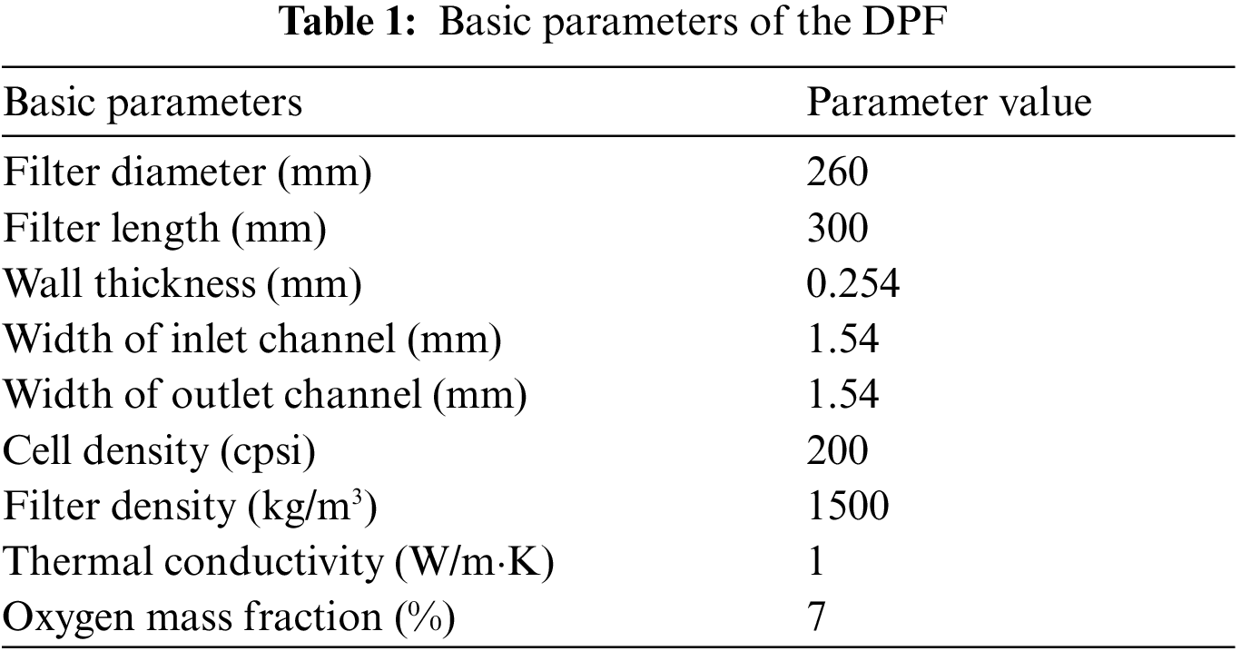
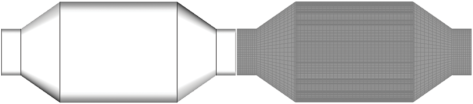
Figure 1: Basic structure and mesh of the DPF
The boundary conditions include the inlet, outlet, wall parameters of the filter body and carrier, the substance transport and post-processing modules. The DPF inlet uses the engine exhaust mass flow rates as the boundary condition, the outlet uses the ambient pressure as the boundary condition, and the wall temperature is set to the ambient temperature of 300 K. The density of the soot layer is 100 kg/m3, the soot migration constant is 1 × 10–15, the permeability of the filter wall is 5 × 10–13 m2 and the soot filter layer permeability is 5 × 10–14 m2. In the soot deep filtration model, the depth filtration threshold is 3 kg/m3 and the depth filtration permeability is 9 × 10–15 m2. The initial soot mass per unit mass of exhaust gas is 0.0005.
In the soot regeneration mode, the O2-thermal mode is chosen. Soot reacts with the oxygen in the exhaust gas to convert carbon into CO and CO2. The regeneration reaction rate increases rapidly by increasing the DPF inlet temperature, so that the soot burns rapidly in a short time.
The mesh independent test was performed with the pressure drop of the filter at the exhaust air flow of 515 kg/h, shown in Fig. 2. The result shows the total mesh number exceeding 576000 has no significant impact on the pressure drop. Therefore, the number of mesh cells for each computational case is about 576000.
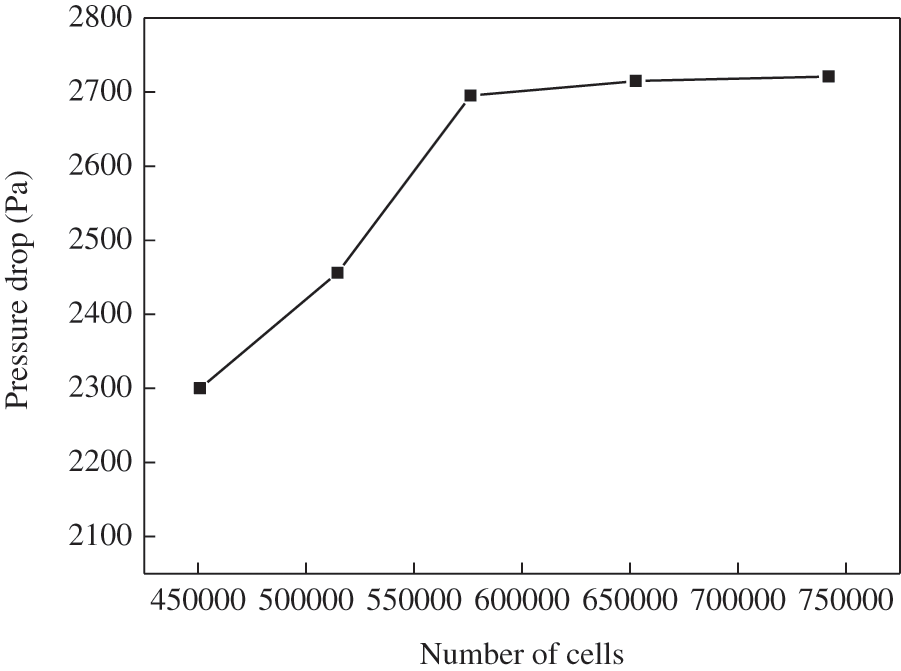
Figure 2: Grid independence analysis
3 Simulation Results and Analysis
3.1 Effect of Exhaust Gas Flow on Particle Trap Process
In this subsection, the results of simulations run by varying the exhaust flows are presented. Fig. 3 shows the variations of the soot concentrations and soot layer thickness with time with the initial soot loading of 0 g/L on the DPF. As can be seen from Fig. 3a, the soot mass concentrations in depth layer first increase and then keep unchanged except at the small exhaust air flow (515 kg/h). Due to the limited ability of the wall surface layer to accumulate soot, it will not increase after reaching a certain level. It is also found that the soot concentrations of the depth filter at the larger flows reach the saturation value of 2.58 g/L at different times. The larger the exhaust mass flow is, the earlier the time to reach the saturation value of soot density. It is noted that the cake filtration gradually dominates and the cake soot mass concentrations increase linearly after deep filtration. Moreover, the cake soot mass concentrations increase with the increase of the exhaust flow. Thus, the total soot mass concentrations in depth and cake layers basically increase linearly with time.
Fig. 3b shows the average soot thickness at different sections along the axial direction. As can be seen from Fig. 3b, the soot distribution in the cake layer has a larger thickness at the front and rear portion of the filter and the position of the lowest point gradually moves to the front as the exhaust flow increases. The soot distribution of the cake layer becomes uneven with the increase of the exhaust flow rate. This is due to the fact that the unevenness of the exhaust inlet flow velocity increases as the exhaust flow rate increases. It is also found that the largest soot cake thickness of 0.07 μm occurs at the rear portion of the filter at the exhaust flow of 1590 m3/h. Compared with the soot of the cake layer, those of the depth layer is thinner except at the low exhaust flow of 515 kg/h.
Fig. 3c shows the deposition distribution of soot in the DPF filter. It is found that soot mass concentration obviously increases with the increase of the exhaust gas flow. As can be seen from the figure, soot is mainly deposited at the filter inlet position and the rear outlet position in the initial stage, and less soot is in the radially outer side and the axial middle position of the filter. As the capture time becomes longer, soot gradually diffuses to the axially intermediate position of the filter, but the shape of the distribution is not changed. Overall, more soot is distributed in the front and rear portion of the filter and less in the middle, showing a concave-shaped distribution. In addition, in the radial direction, there is more soot distributed in the axial center position and less in the outer side, showing a convex-shaped distribution.
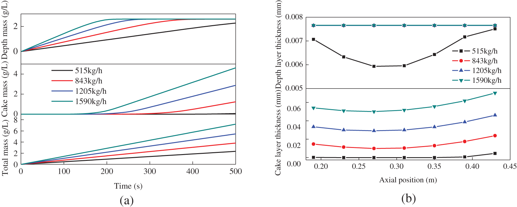
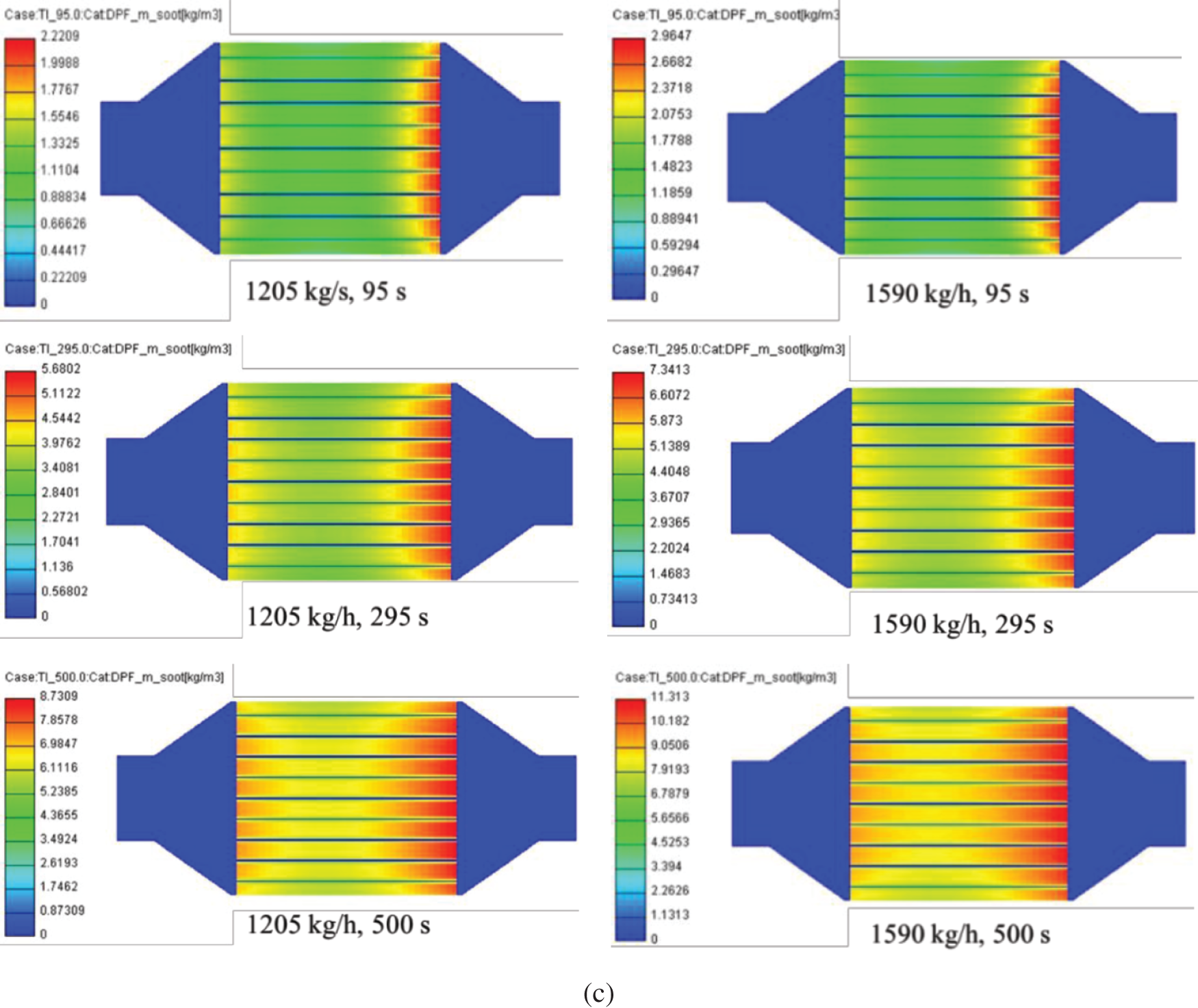
Figure 3: Effects of exhaust gas flow on soot trap process with an initial soot loading of 0 g/L: (a) soot concentration, (b) soot thickness, (c) spatial distributions of soot concentration
3.2 Effect of Exhaust Gas Flow on DPF Regeneration Process
The DPF regeneration process at different exhaust gas flows with an initial soot loading of 10 g/L is presented in Fig. 4. The regeneration mode is the active regeneration mode of oxygen combustion by heating the exhaust gas temperature to 850 K at 100 s.
The peaks of the mean filter temperatures decrease with the increase of the exhaust flow, but appear early due to higher exhaust gas temperature. This is similar to the result reported by Deng et al. [20]. The peak temperature at the exhaust gas flow of 515 kg/h is about 900 K, which is higher than the heating temperature. Correspondingly, the pressure drops of the filter increase and the maximum pressure drops appear earlier when the DPF inlet mass flow rates increase. It also can be seen in Fig. 4b that the DPF filter pressure drops first increase, then decrease and finally keep unchanged.
The decreases in soot concentrations also indicate that the DPF regeneration has begun, shown in Fig. 4c. The corresponding exhaust temperatures at large exhaust gas flows are high, which accelerates the DPF regeneration. The soot concentrations almost keep unchanged after about 220 s, which indicates the completion of the DPF regeneration, just like the filter pressure drops. There is a difference between the soot cake layer thickness and the soot depth layer thickness at different exhaust gas flows. The cake layer thickness is mainly distributed in the front and middle portion of the DPF and the layer thickness is mainly distributed in the middle and rear portion of the DPF except at the high exhaust flow of 1590 kg/h.
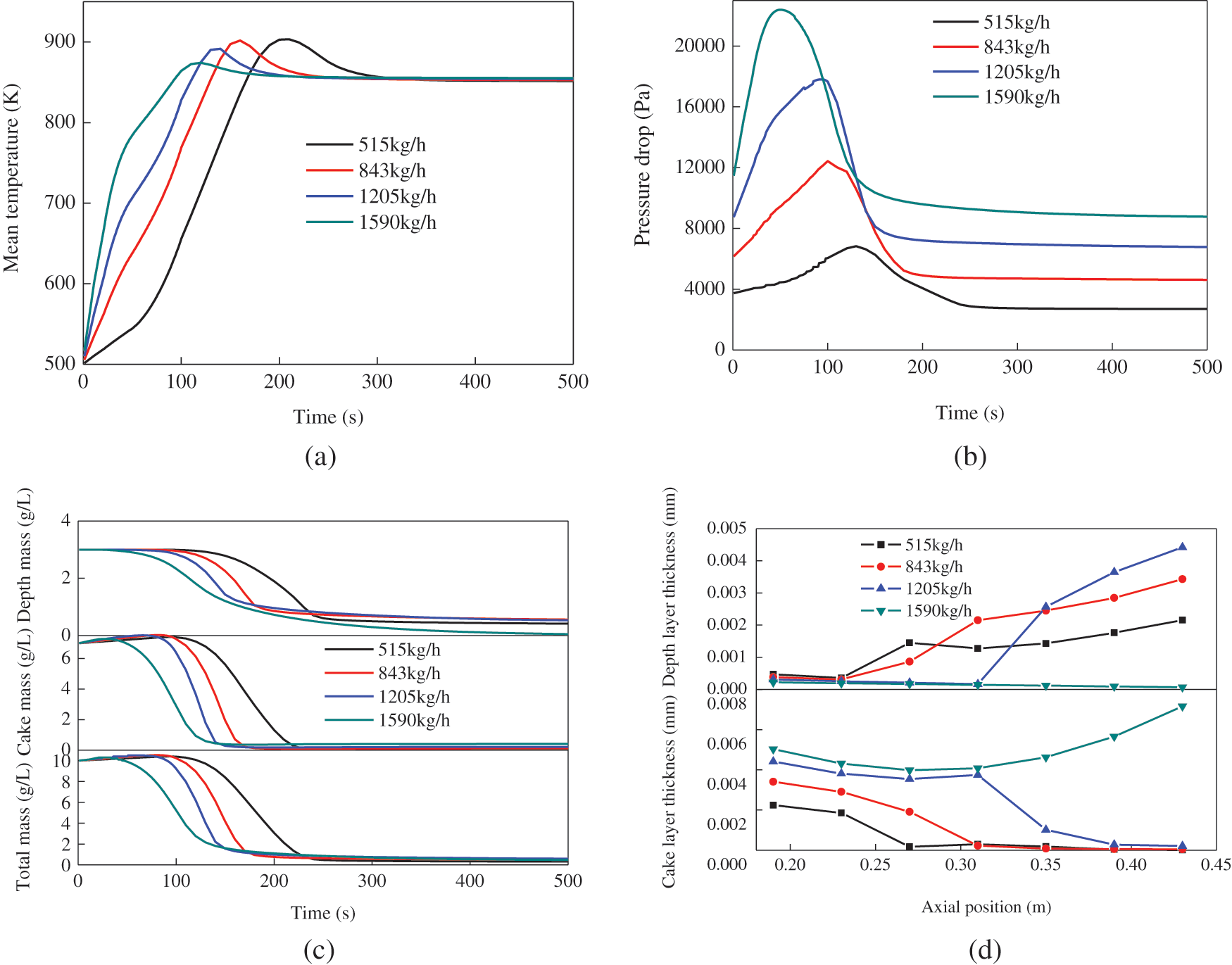
Figure 4: Effects of exhaust gas flow on DPF regeneration process with an initial soot loading of 10 g/L: (a) mean filter temperature, (b) pressure drop, (c) soot concentration, (d) soot thickness
3.3 Effect of Initial Soot Loading on DPF Regeneration
Fig. 5 shows the effect of initial soot loadings on the DPF regeneration at the exhaust gas flow of 1205 kg/h. For this case, the exhaust gas is heated to the temperature of 850 K when the regeneration is in progress for 100 s.
As can be seen in Fig. 5a, the mean filter temperatures have a slight increase with the increase of the initial soot loading. This reason is that more heat is released with more soot oxidation. This temperature variation is similar to the result in reference [25]. It is easily found that the initial soot loading and exhaust gas flow have similar effects on the pressure drops and soot concentrations. As the initial soot loading increase, the pressure drops and soot concentrations increase in the first 100 s due to soot clogging. This is similar to the result conducted by di Sarl et al. [27]. However, the initial soot loadings have little effect on the pressure drops and soot concentrations when the DPF regeneration begins after 100 s.
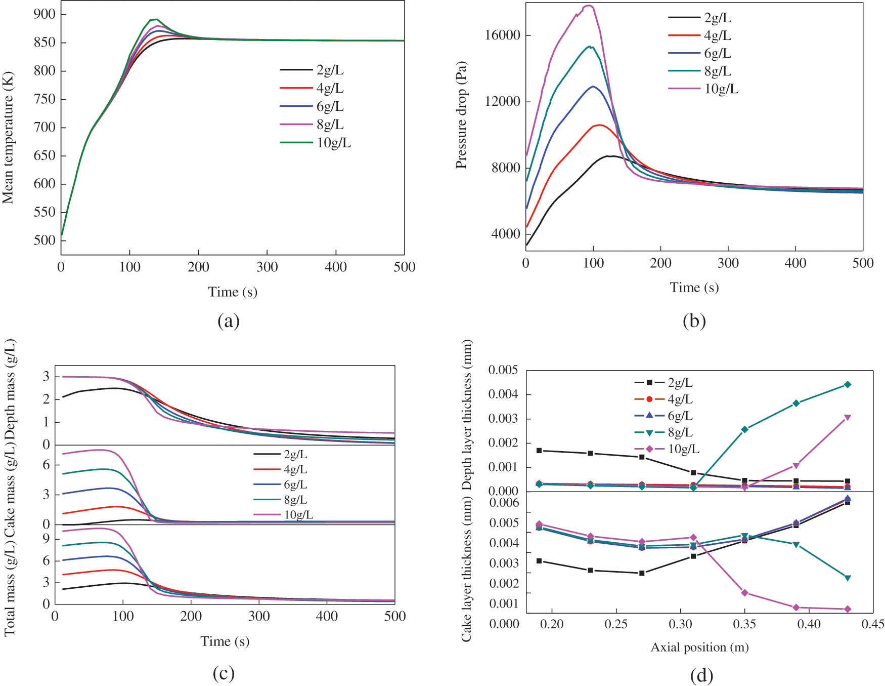
Figure 5: Effects of initial soot loading on DPF regeneration process at the exhaust gas flow of 1205 kg/h: (a) mean filter temperature, (b) pressure drop, (c) soot concentration, (d) soot thickness
There are some differences between the distributions of deep soot thickness and cake soot thickness with different initial soot loadings. In the front portion of the DPF, the deep soot thickness increases when the initial soot loading is from 2 g/L to 4 g/L, but the cake soot thickness decreases. When the initial soot loading is greater than 4 g/L, it has no effect on the cake soot thickness in the filter front. In the rear portion of the filter, the deep soot thickness with higher initial soot loadings is thicker, but the cake soot thickness is smaller. Similarly, the initial small and middle soot loadings have no effect on soot thickness at the rear portion of the filter. The above non-uniformity of soot distribution along the axial direction is attributed to the non-uniformity of the DPF temperature distribution.
3.4 Effect of Heating Mode on DPF Regeneration
Figs. 6–8 show the effect of heating mode on the DPF regeneration at the exhaust 1205 kg/h. Fig. 6 presents the results of the DPF regeneration at different heating temperatures. The exhaust gas is heated to constant temperatures from 50 s to 100 s and then the temperatures are kept constant, as shown in Fig. 6a. The maximum filter temperatures increase with the increase of the heating temperature and the highest temperatures appear earlier. When the heating temperature is 900 K, the peak filter temperature is 1022 K in 140 s.
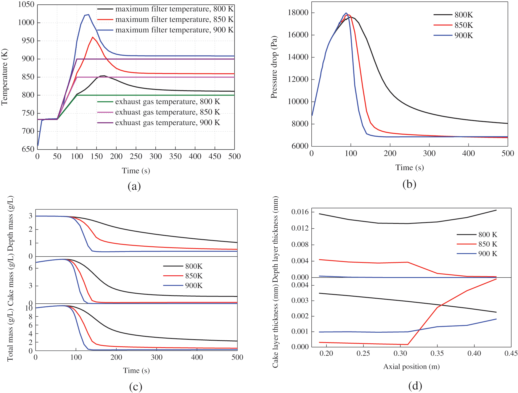
Figure 6: Effect of heating temperature on DPF regeneration process with the initial soot loading of 10 g/L at the exhaust 1205 kg/h: (a) temperature, (b) pressure drop, (c) soot concentration, (d) soot thickness
It is easily found that the pressure drops and soot mass concentrations decrease with the increase of the heating temperature. they attenuate sharply from 100 s to 140 s especially at 850 K and 900 K. The increase in the heating temperature is also advantageous to reduce the thickness in the soot cake layer. However, it seems that the heating temperature has no obvious effect on the thickness in the soot depth layer. Overall, the heating temperature of 850 K can achieve the DPF regeneration efficiency of 94%. Therefore, it is the suitable DPF regeneration temperature.
Fig. 7 shows the results of on the DPF regeneration process at different heating rates. For this case, two heating methods for slow heating and rapid heating are used at the initial exhaust temperature of 733 K, as shown in Fig. 7a. The highest filter temperatures for slow heating and rapid heating are 994 K and 960 K, respectively and the corresponding times are 96 s and 140 s.
It can be seen from Figs. 7b and 7c that the moment of the soot concentrations and pressure drops decline is different due to the different times to reach the soot ignition temperature. At rapid heating mode, there is an early significant drop in soot mass concentration in 80 s. As can be seen from Fig. 7d, the heating rate has no influence on the distributions of the soot thickness in the DPF front but has some influence in the DPF back. The rapid heating mode is conducive to reduce the soot thickness in the cake layer but is not helpful for the reduction of the soot thickness in the depth layer.
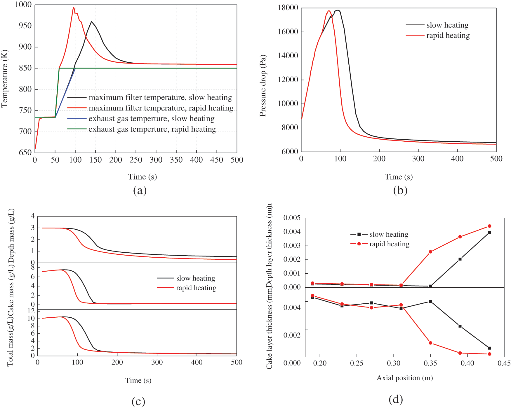
Figure 7: Effect of heating rate on DPF regeneration process with the initial soot loading of 10 g/L at the exhaust 1205 kg/h: (a) temperature, (b) pressure drop, (c) soot concentration, (d) soot thickness
Fig. 8 shows the results of on the DPF regeneration process at different heating times. In this case, two heating modes of continuous heating and short time heating are used at the initial exhaust temperature of 733 K, shown in Fig. 8a. For the short time heating, the exhaust gas temperature is heated to 850 K in 100~120 s and decreases to 733 K in 120~170 s. There is no difference in the maximum filter temperatures between the two modes before 150 s, but there is large difference after 150 s. The maximum filter temperature at the short time heating has a greater attenuation than that at the continuous heating.
The duration of heating time has obvious effects on the pressure drop and soot concentration, shown in Figs. 8b–8d. Shorter heating time is insufficient to oxidate the soot in the cake layer and depth layer. When the heating stops, the soot concentrations increase. Correspondingly, the soot thickness in the depth and cake layers for a shorter heating time presents a lower concentration distribution than that for continuous heating. As a result, the pressure drop for the short time heating increases due to more soot deposits.
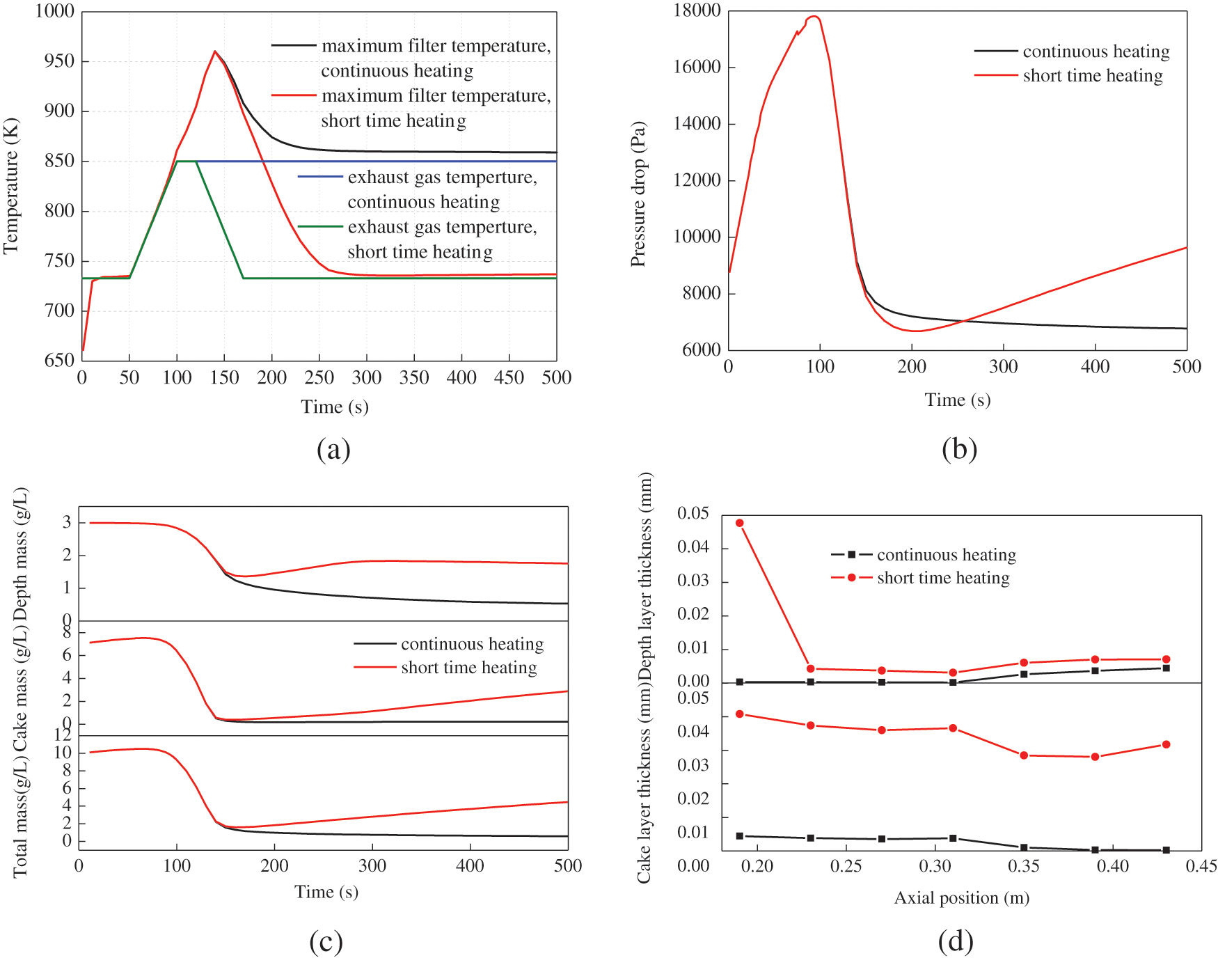
Figure 8: Effect of heating time on DPF regeneration process with the initial soot loading of 10 g/L at the exhaust 1205 kg/h: (a) temperature, (b) pressure drop, (c) soot concentration, (d) soot thickness
It is found from the variation of the pressure drops and soot mass concentrations that the exhaust gas flows and initial loadings obviously affect the soot trap process. The peak of the mean filter temperatures is about 900 K under all engine operating conditions, being safe for the DPF material. As the initial soot loading is from 2 g/L to 4 g/L, the deep soot thickness in the front of the DPF increases, but the cake soot thickness decreases. The initial soot load over 4 g/L has no effect on the cake of the cake in front of the DPF. For the DPF regeneration, the proper temperature of 850 K for heating exhaust gas should be chosen, which can achieve 94% DPF regeneration efficiency. Compared with the heating duration, the heating rate is a more important factor affecting the soot formation and flow resistance.
Funding Statement: This work was supported by the National Key Research and Development Program of China (Grant No. 2017YFE0116100).
Conflicts of Interest: The authors declare that they have no conflicts of interest to report regarding the present study.
1. Yusuf, A. A., Yusuf, D. A., Jie, Z., Bello, T. Y., Tambaya, M. et al. (2022). Influence of waste oil-biodiesel on toxic pollutants from marine engine coupled with emission reduction measures at various loads. Atmospheric Pollution Research, 13, 101258. DOI 10.1016/j.apr.2021.101258. [Google Scholar] [CrossRef]
2. Ampah, J. D., Yusuf, A. A., Afrane, S., Jin, C., Liu, H. F. (2021). Reviewing two decades of cleaner alternative marine fuels: Towards IMO’s decarbonization of the maritime transport sector. Journal of Cleaner Production, 320, 128871. DOI 10.1016/j.jclepro.2021.128871. [Google Scholar] [CrossRef]
3. Ni, P. Y., Wang, X. L., Li, H. (2020). A review on regulations, current status, effects and reduction strategies of emissions for marine diesel engines. Fuel, 279, 118477. DOI 10.1016/j.fuel.2020.118477. [Google Scholar] [CrossRef]
4. Yusuf, A. A., Inambao, F. L., Ampah, J. D. (2022). Evaluation of biodiesel on speciated PM2.5, organic compound, ultrafine particle and gaseous emissions from a low-speed EPA Tier II marine diesel engine coupled with DPF, DEP and SCR filter at various loads. Energy, 239, 121837. DOI 10.1016/j.energy.2021.121837. [Google Scholar] [CrossRef]
5. Lao, C. T., Akroyd, J., Eaves, N., Smith, A., Morgan, N. et al. (2019). Modelling particle mass and particle number emissions during the active regeneration of diesel particulate filters. Proceedings of the Combustion Institute, 37(4), 4831–4838. DOI 10.1016/j.proci.2018.07.079. [Google Scholar] [CrossRef]
6. Zhang, J., Wong, V. W., Shuai, S., Chen, Y., Sappok, A. (2018). Quantitative estimation of the impact of ash accumulation on diesel particulate filter related fuel penalty for a typical modern on-road heavy-duty diesel engine. Applied Energy, 229(3), 1010–1023. DOI 10.1016/j.apenergy.2018.08.071. [Google Scholar] [CrossRef]
7. Smith, J. D., Ruehl, C., Burnitzki, M., Sobieralski, W., Dwyer, H. (2019). Real-time particulate emissions rates from active and passive heavy-duty diesel particulate filter regeneration. Science of the Total Environment, 680, 132–139. DOI 10.1016/j.scitotenv.2019.04.447. [Google Scholar] [CrossRef]
8. Stepień, Z., Ziemiański, L., Żak, G., Wojtasik, M., Jeczmionek, L. et al. (2015). The evaluation of fuel borne catalyst (FBC’s) for DPF regeneration. Fuel, 161, 278–286. DOI 10.1016/j.fuel.2015.08.071. [Google Scholar] [CrossRef]
9. Soltani, S., Andersson, R., Andersson, B. (2018). The effect of exhaust gas composition on the kinetics of soot oxidation and diesel particulate filter regeneration. Fuel, 220, 453–463. DOI 10.1016/j.fuel.2018.02.037. [Google Scholar] [CrossRef]
10. Ko, J., Si, W., Jin, D., Myung, C. L., Park, S. (2016). Effect of active regeneration on time-resolved characteristics of gaseous emissions and size-resolved particle emissions from light duty diesel engine. Journal of Aerosol Science, 91(11), 62–77. DOI 10.1016/j.jaerosci.2015.09.007. [Google Scholar] [CrossRef]
11. E, J. Q., Zhao, M. Y., Zuo, Q. S., Zhang, B., Zhang, Z. Q. et al. (2020). Effects analysis on diesel soot continuous regeneration performance of a rotary microwave-assisted regeneration diesel particulate filter. Fuel, 260(11), 116353. DOI 10.1016/j.fuel.2019.116353. [Google Scholar] [CrossRef]
12. Kurien, C., Srivastava, A. K., Gandigudi, N., Anand, K. (2020). Soot deposition effects and microwave regeneration modelling of diesel particulate filtration system. Journal of the Energy Institute, 93(2), 463–473. DOI 10.1016/j.joei.2019.07.005. [Google Scholar] [CrossRef]
13. Chen, K., Martirosyan, K. S., Luss, D. (2011). Temperature gradients within a soot layer during DPF regeneration. Chemical Engineering Science, 66(13), 2968–2973. DOI 10.1016/j.ces.2011.03.037. [Google Scholar] [CrossRef]
14. Chong, H. S., Aggarwal, S. K., Lee, K. O., Yang, S. Y. (2011). Measurements of heat release of diesel PM for advanced thermal management strategies for DPF regeneration. Combustion Science and Technology, 183(12), 1328–1341. DOI 10.1080/00102202.2011.594346. [Google Scholar] [CrossRef]
15. Yamamoto, K., Yamauchi, K. (2013). Numerical simulation of continuously regenerating diesel particulate filter. Proceedings of the Combustion Institute, 34(2), 3083–3090. DOI 10.1016/j.proci.2012.06.117. [Google Scholar] [CrossRef]
16. Yu, M. T., Luss, D., Balakotaiah, V. (2013). Analysis of flow distribution and heat transfer in a diesel particulate filter. Chemical Engineering Journal, 226, 68–78. DOI 10.1016/j.cej.2013.04.026. [Google Scholar] [CrossRef]
17. Liu, B., Sun, P., Aggarwal, S. K., Zhao, S. B., Huang, B. (2020). An experimental-computational study of DPF soot capture and heat regeneration. International Journal of Green Energy, 17(4), 301–308. DOI 10.1080/15435075.2020.1727481. [Google Scholar] [CrossRef]
18. Meng, Z. W., Chen, C., Li, J. S., Fang, J., Tan, J. et al. (2020). Particle emission characteristics of DPF regeneration from DPF regeneration bench and diesel engine bench measurements. Fuel, 262(1), 116589. DOI 10.1016/j.fuel.2019.116589. [Google Scholar] [CrossRef]
19. Yu, M. T., Luss, D. (2012). Inlet cone effect on particulate matter deposition and regeneration temperature in a diesel particulate filter. Industrial & Engineering Chemistry Research, 51(9), 3791–3800. DOI 10.1021/ie202226r. [Google Scholar] [CrossRef]
20. Deng, Y. W., Cui, J. H., Cui, J. Q., Zhang, B., Zhao, X. H. et al. (2017). Investigations on the temperature distribution of the diesel particulate filter in the thermal regeneration process and its field synergy analysis. Applied Thermal Engineering, 123(8), 92–102. DOI 10.1016/j.applthermaleng.2017.05.072. [Google Scholar] [CrossRef]
21. Lupše, J., Campolo, M., Soldati, A. (2016). Modelling soot deposition and monolith regeneration for optimal design of automotive DPFs. Chemical Engineering Science, 151(6), 36–50. DOI 10.1016/j.ces.2016.05.008. [Google Scholar] [CrossRef]
22. Zhang, B., E, J. Q., Gong, J. K., Yuan, W. H., Zuo, W. et al. (2016). Multidisciplinary design optimization of the diesel particulate filter in the composite regeneration process. Applied Energy, 181(2), 14–28. DOI 10.1016/j.apenergy.2016.08.051. [Google Scholar] [CrossRef]
23. Ebrahimnataj, M. R., Ehteram, M. A., Sahebi, M., Abdolmaleki, S. (2018). Numerical and experimental study on the gaseous emission and back pressure during regeneration of diesel particulate filters. Transportation Research Part D: Transport and Environment, 62(1), 11–26. DOI 10.1016/j.trd.2018.02.007. [Google Scholar] [CrossRef]
24. Yu, M. T., Luss, D., Balakotaiah, V. (2013). Regeneration modes and peak temperatures in a diesel particulate filter. Chemical Engineering Journal, 232(9), 541–554. DOI 10.1016/j.cej.2013.08.006. [Google Scholar] [CrossRef]
25. Chen, T., Wu, Z. X., Gong, J. K., E, J. Q. (2016). Numerical simulation of diesel particulate filter regeneration considering ash deposit. Flow Turbulence Combustion, 97(3), 849–864. DOI 10.1007/s10494-016-9717-6. [Google Scholar] [CrossRef]
26. Koltsakis, G. C., Stamatelos, A. M. (1997). Modes of catalytic regeneration in diesel particulate filters. Industrial & Engineering Chemistry Research, 36(10), 4155–4165. DOI 10.1021/ie970095m. [Google Scholar] [CrossRef]
27. di Sarli, V., Di Benedetto, A. (2018). Combined effects of soot load and catalyst activity on the regeneration dynamics of catalytic diesel particulate filters. AIChE Journal, 64(5), 1714–1722. DOI 10.1002/aic.16047. [Google Scholar] [CrossRef]
 | This work is licensed under a Creative Commons Attribution 4.0 International License, which permits unrestricted use, distribution, and reproduction in any medium, provided the original work is properly cited. |