| Energy Engineering |
DOI: 10.32604/ee.2022.019695
ARTICLE
An Advanced Control Strategy for Dual-Actuator Driving System in Full-Scale Fatigue Test of Wind Turbine Blades
1School of Mechanical Engineering, Shandong University of Technology, Zibo, 255049, China
2Lianyungang Zhongfu Lianzhong Composite Croup Co., Ltd., Lianyungang, 222000, China
*Corresponding Author: Xuemei Huang. Email: huangxuemei@sdut.edu.cn
Received: 09 October 2021; Accepted: 13 December 2021
Abstract: A new dual-actuator fatigue loading system of wind turbine blades was designed. Compared with the traditional pendulum loading mode, the masses in this system only moved linearly along the loading direction to increase the exciting force. However, the two actuators and the blade constituted a complicated non-linear energy transferring system, which led to the non-synchronization of actuators. On-site test results showed that the virtual spindle synchronous strategy commonly used in synchronous control was undesirable and caused the instability of the blade’s amplitude eventually. A cross-coupled control strategy based on the active disturbance rejection algorithm was proposed. Firstly, a control system model was built according to the synchronization error and tracking error. Furthermore, based on arranging the transition process, estimating the system state and error feedback, and compensating disturbance, an active disturbance rejection controller was designed by adopting the optimal control function. Finally, on-site test results showed that the cross-coupled control strategy based on the active disturbance rejection algorithm could ensure the synchronization of two actuators. The maximum speed synchronization error of the two motors was less than 16 RPM, the displacement synchronization error of the two actuators was less than 0.25 mm and approaching zero after 4 seconds, and the peak value of vibration of the blade was less than 5 mm, which satisfied the fatigue test requirement.
Keywords: Wind turbine blades; full-scale fatigue test; synchronous control; cross-coupled control strategy; active disturbance rejection control algorithm
As the main components of wind turbines, the blades are always under long-term alternating loads. A large number of accidents and research results show that fatigue is one of the main failure mechanisms for blades [1,2]. So, fatigue testing of a wind turbine blade is the most effective and reliable method to find weaknesses in a blade’s design [3,4]. At present, the existing full-scale fatigue loading method is mainly composed of centrifugal pendulum resonance loading and hydraulic forced loading, which is almost applied to onshore wind power blades [5–8]. Recently, with the development of offshore wind power, the corresponding wind turbine requires to output more power and have a larger blade size [9–11]. However, with the increase of blade size, the loading force is also needed to enlarge. In the pendulum resonance loading mode, only the vertical component of the centrifugal force does useful work in fatigue loading, which lowers energy utilization. Moreover, single-actuator power limits the loading capacity, and it is challenging to achieve the amplitude of the blade [11–13].
The fatigue loading system driven by a dual-actuator for wind turbine blades was a new type of full-scale test method proposed in this paper to overcome the limitations of the existing methods. The fatigue load was achieved by controlling the reciprocating linear motion of two actuators distributed symmetrically on the spatial structure. Compared with the traditional pendulum loading method, the masses in the loading mode only moved linearly along the loading direction. Thus, the inertia force generated by the acceleration and deceleration could fully act on the wind turbine blade, and the energy utilization rate was higher. As the two actuators loaded synchronously, the output power doubled and the loading force increased significantly, which could meet the demand for the amplitude value of the blade. However, due to the difference in the parameters of the two actuators and the effect of the load disturbance during the test, it was difficult for the two actuators to achieve complete synchronization in the displacement and velocity. This resulted in the magnitude of the phase difference of counterforce produced by the two actuators, and an additional torque that affected the stability of the blade’s amplitude at the same time except the resultant force generated in the loading direction. The additional torque would twist the blade, and even cause damage. So the study of dual actuator synchronization on the impact of wind power blades is significant. Many researchers have studied extensively synchronous motor control [14–16]. In 2013, Snowberg et al. [17] conducted a dual-axis fatigue test on blades (50 m) for the first time. Hughes et al. [18] conducted a dual-axis fatigue test on a 9-meter blade through a universal resonant exciter, which is authorized by MTS systems. Wind technology test center (WTTC) [19] introduced a simple simulation technology, including adding virtual mass, so that the tuning of frequency and torque curves in one direction is independent of the other, proving the possibility of using ground-based resonant exciter. Embry riddle the University of Aeronautics and NREL [20] jointly proposed an innovative test method for fatigue test of wind turbine blades, called the biaxial phase-locked resonance excitation method. Eder et al. [21] proved through experiments that, compared with a single frequency, the randomness of the actual load history can be restored more realistically through the combination of multiple frequencies. This new method of multi-frequency loading can reduce the time of fatigue test by increasing the cycle content in the time process and avoiding the use of tuned mass blocks, to meet the requirements of the most advanced fatigue test.
In this dual-actuator fatigue loading scheme, two actuator’s speeds varied sinusoidally and the traditional synchronous control could not meet the control requirements satisfactorily. According to [22], the cross-coupling control strategy could improve the synchronization of the system. However, the cross-coupling control effect was not ideal because the actuators in this paper working outdoors were under complex environmental conditions, and the load disturbance was large. Therefore, considering the characteristics of the fatigue loading test, an active disturbance rejection control algorithm with an estimated perturbation function was introduced into the cross-coupling control strategy to solve the synchronous control problem. In the test site, this control system realized the synchronization of the two actuators and proved the effectiveness of the control strategy. In addition, it should be said that this driving system is only applicable to blades with a length of more than 60 meters. For shorter blades, the single-actuator system can make a higher efficiency in fatigue tests.
Before the test, the loading scheme and vibration analysis were conducted in Section 2. The design of the cross-coupling controller with control theory was done in Section 3. The design of the auto disturbance rejection controller with feedback control theory was done in Section 4. Then the on-site test is established and implemented, and the synchronization error for evaluation was collected through the test results, see Section 5.
2 Vibration Analysis of Dual-Actuator Fatigue Loading System
2.1 Dual-Actuator Fatigue Loading Test Scheme
The fatigue loading equipment driven by a dual-actuator consisted of three subsystems: power system, control system, and detection system. The root of the wind turbine blade was fixed on the cylindrical base by the embedded bolts, and two sets of identical actuators were symmetrically mounted on both sides of the wooden saddle fixture. Each actuator mainly included a servo motor, a ball screw nut pair, a slider group, a set of counterweight blocks, two guide rails, and two limit switches. The servo motor shaft was connected to the ball screw through the coupling and sliders were mounted on the screw nut. The ball screw nut pair converted the rotational motion of the motor into the linear motion of sliders. The counterweight block with adjustable symmetrical masses was mounted on the slide group, and two limit switches were fixed on the upper and lower ends of the actuator, respectively. In the fatigue test, two actuators were controlled to do the synchronous sinusoidal motion with the natural frequency of the blade, resulting in sinusoidal exciting force. For each actuator, the zero places of the movement were located by limit switches which prevented the over-travel displacement of slides at the same time. The magnitude of the exciting force could be adjusted by adjusting the masses of the counterweight block or the actuators’ amplitude. A laser range meter was used to measure the amplitude of the blade in the loading direction and passed the data to the host computer by RS485 cable. The dual-actuator fatigue loading scheme is shown in Fig. 1a. Fig. 1b presents the fixed model of two actuators and Fig. 1c illustrates exploded view of one actuator.
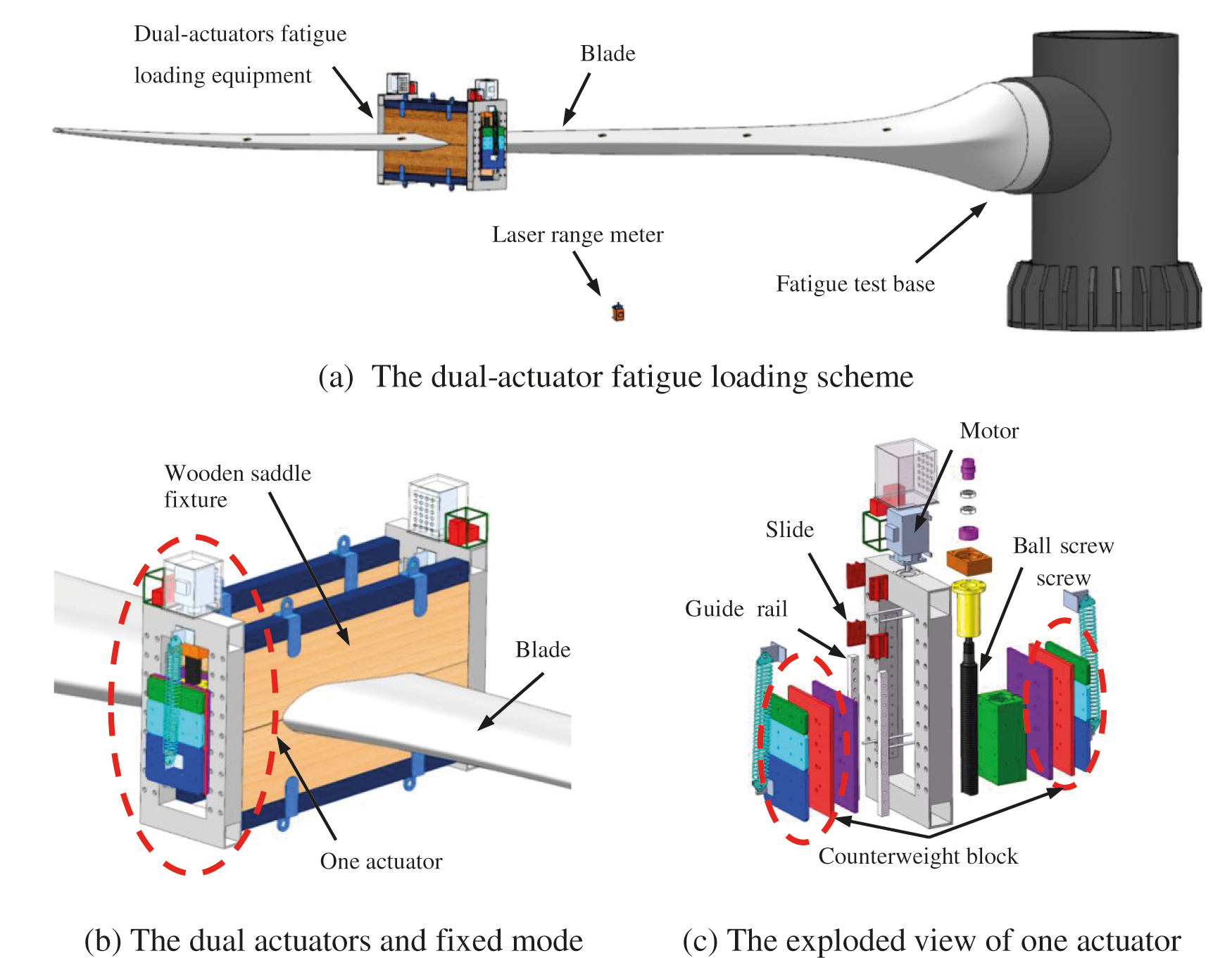
Figure 1: The scheme and structure of dual-actuator fatigue loading system
The blade amplitude is calculated according to the literature [23]. The influence of the weight of the global loading system on the target force is considered in the calculation. The initial control schematic diagram of two actuators is shown in Fig. 2, where a motion control card was adopted with a virtual spindle synchronous strategy commonly used in synchronous control. The blade displacement collected by the laser range meter was applied to determine the amplitude of actuators by the comparison calculation of the controller.
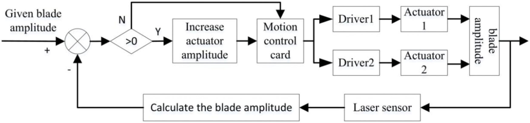
Figure 2: The initial control schematic diagram
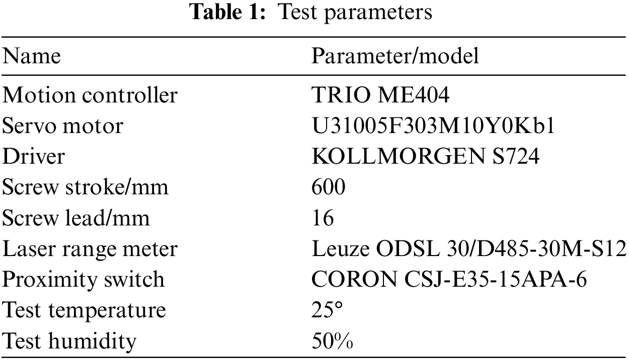
In Wind Blade Testing Center of Lianyungang Zhongfu Lianzhong Composites Group Co., Ltd. (China), a blade LZ 5.0-62 (The power is 5 MW, and the length is 62 meters) was applied to test the synchronous exciting performance of dual actuators. The test parameters are shown in Table 1.
The speeds of the motors and other parameters were displayed and recorded by Driver GUI software and the displacements of the actuators were obtained through the conversion of the rotatory angles of the motors. Fig. 3a is the overview of the whole test site. Figs. 3b and 3c are the local enlarged pictures.
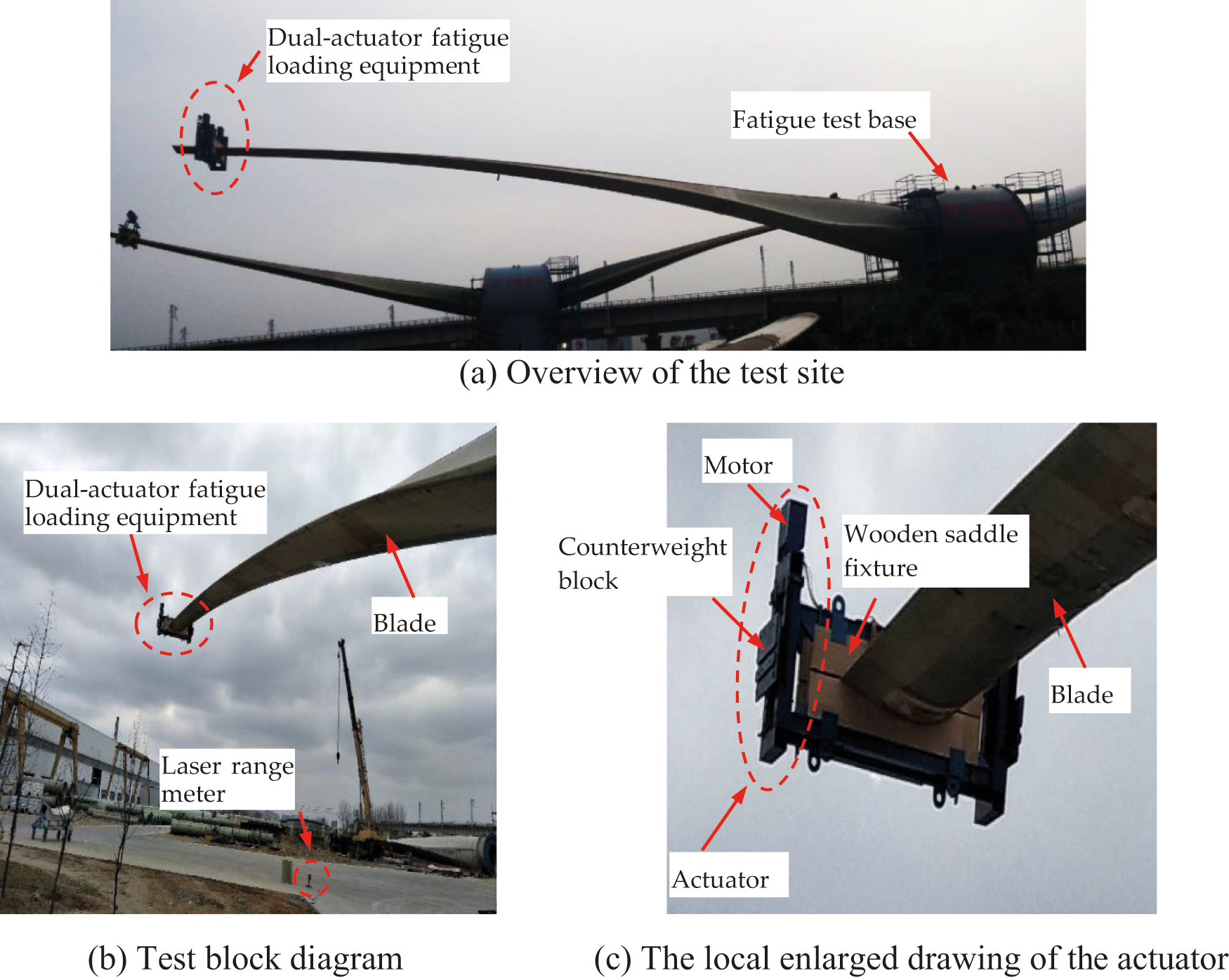
Figure 3: On-site test of dual-actuator fatigue loading system
The periods of actuators were s both set to 1910 ms. At this period, the frequency equaled the natural frequency of the blade to form the resonance condition. The amplitudes of actuators were both set to 200 mm which was converted from the amplitude of the blade (in this paper, the period, amplitude, and displacement of the actuator mean these parameters of the linear moving part of the actuator).The speed synchronization error of the motors is shown in Figs. 4 and 5 presents the displacement synchronization error of two actuators. To obtain the fluctuation error of the amplitude of the blade in the resonance condition, the peak errors of the amplitude of some vibrating cycles were compared to the set value, as shown in Fig. 6.
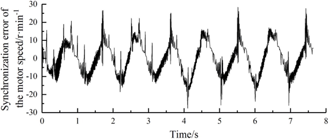
Figure 4: The speed synchronization error of the motors
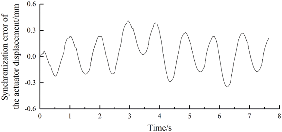
Figure 5: The displacement synchronization error of the actuators
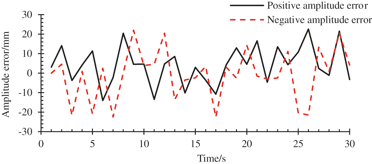
Figure 6: Peak errors of the blade amplitude for a given range of time
In Fig. 4, it could be seen that the speed synchronization error of the motors was within ±30 RPM. In Fig. 5, the trend of the displacement synchronization error of two actuators was similar to that of the speed synchronization error in Fig. 4, and the error value fluctuated regularly within ±0.5 mm. Compared two synchronization error curves mentioned above, there was a correlation. In other words, in the single stroke of the actuators, the speed synchronization error and displacement synchronization error both had an accumulation phenomenon, and the maximum error value appeared at the end of the trip.
In Fig. 6, the maximum amplitude error of the blade was 23 mm. The significant amplitude error influences the accuracy of the fatigue loading test. So, the synchronous effect of the two actuators was unsatisfactory in this control strategy, which led to the unstable amplitude of the blade. The accuracy and credibility of the fatigue test were reduced, thus, the synchronization of the two actuators needed to be controlled accurately.
3 Design of Cross-Coupled Control Strategy
The fatigue test system of wind turbine blades driven by a dual-actuator needs the synchronous loading of two actuators. However, the parameters of the two axes of the motors will be different inevitably. Besides, the equipment working outdoors at high altitudes is vulnerable to severe weather such as gale, rain, and snow, which makes it difficult for the two actuators to achieve satisfied synchronization in displacement and speed. In this paper, a cross-coupling control strategy was adopted to improve the synchronization of the two actuators by integrating two independent actuator control systems into a closed-loop system. The basic principle is that the speed compensation value of each actuator is calculated by the cross-coupling controller according to the actuators’ synchronization error. Then the speed compensation value is added to the speed of each actuator to eliminate the synchronization error of the dual actuators. However, due to the large disturbance of the dual-actuator fatigue loading system and the contradiction between overshoot and fastness, the error curve would appear larger overshoot and show obvious fluctuations if the cross-coupling controller was only used under the premise of ensuring fastness. Hence, the Active Disturbance Rejection Control algorithm (ADRC algorithm) was introduced into the cross-coupling control strategy, and the tracking accuracy of the actuator was improved by the estimated disturbance function of the ADRC algorithm, which reduces the influence of the disturbance on the synchronization and the overshoot of cross-coupling control. The cross-coupling synchronization control strategy combined with the ADRC algorithm is shown in Fig. 7.
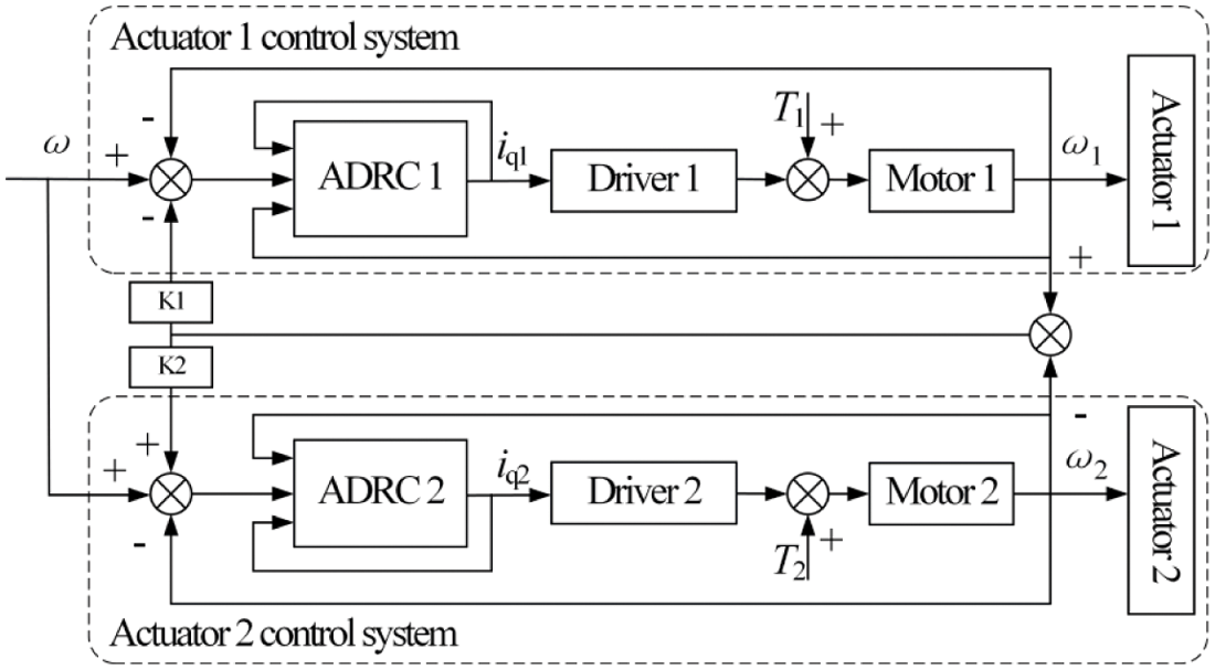
Figure 7: The synchronization control strategy of cross-coupling based on ADRC algorithm
In Fig. 7, ω is the given speed of the system, ω1 and ω2 are the tracking speed of the two actuators respectively, iq1 and iq2 are the currents of two motors in q axis respectively, additionally, k1 and k2 are the speed compensation gains of the two motors, respectively.
As can be seen from the cross-coupling control strategy shown in Fig. 7, to guarantee the synchronization of two actuators, ω1 is required to be equal to ω2, which can be expressed as follows:
where t is the time variable.
Since the selected actuator motors were the synchronous motors in the same model and the same batch, the two motors have similar performance and the values of k1 and k2 are almost the same.
4 Design of Active Disturbance Rejection Controller
The outputs of dual actuators followed the same input, and as a result, the synchronization error of the dual actuators is closely related to the tracking error of the individual actuator. By improving the tracking accuracy and stability of each actuator, the synchronization error of double actuators can be reduced indirectly. In terms of this, two actuators are controlled by two independent active disturbance rejection controllers designed to reduce the tracking error and enhance synchronization. The structure of one active disturbance rejection controller is shown in Fig. 8.
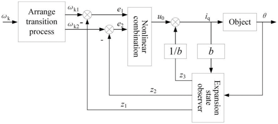
Figure 8: The structure of active disturbance rejection controller
In Fig. 8, ωk is the angular velocity of the motor after compensating by the cross-coupled controller, ωk1 and ωk2 are the tracking signals and the approximate differential signal of ωk, respectively, and
where,
From the formula (2) it could be seen that the single actuator system was a second-order system, and the system model can be expressed as follows:
In Eqs. (2) and (3), iq is the current of q-axis, ωr is the mechanical angular velocity of the motor, TL is the load torque of the motor, ψf is the flux linkage of excitation winding, p is the pole pair of the motor, B is the friction coefficient of the motor, J is the rotary inertia of the motor, θ is the shaft angle of the motor, y is the actuator position; r is the screw radius and α is the screw lead angle.
The dual-actuator fatigue loading system used the inertial force generated by the sine acceleration movement of the actuator as the exciting source to load the blade, which determined that the system must have fastness to ensure the generation of the normative sinusoidal force. In order to solve the contradiction between system speed and overshoot, speed ωk adjusted by the cross-coupling controller was used as the input of the active disturbance rejection controller, and the transition process is as follows:
where, fhan is the optimal control synthesis function and the specific expression is shown below:
In Eqs. (4) and (5), r0 is the rapid factor that can adjust the trace speed and h is the sampling step.
In order to monitor the operating conditions of the actuator system, the following state observers are established to track and estimate system state and disturbances with the θ and iq:
In order to avoid the phenomenon of high-frequency flutter, the traditional power function is changed to the continuous power function with a linear segment near the origin:
In Eqs. (6) and (7), δ is the length of the interval of the linear segment, and β01, β02, and β03 are the adjustment parameters of the observer.
Although the linear error feedback could adjust quickly, it still had a significant error. In order to improve the feedback precision of the system, the feedback rules based on optimal control synthesis function are adopted: linear error feedback can adjust quickly, but it still has a significant error.
where c is the coefficient of feedback control, r1 is the rapid factor that can adjust the trace speed and h1 is the sampling step.
The error control value u0 is determined the result by the compensation of the disturbance estimate z3:
From the design process of the active disturbance rejection controller, it could be seen that the active disturbance rejection controller had the advantage of not relying on the exact mathematical model. At the same time, the transition process was arranged, and the expansion state observer was added, thus, the contradiction between the fastness and the overshoot could be solved. Moreover, the internal and external disturbances of the system could be estimated in real-time and the compensation could be performed, which improves the tracking precision and anti-jamming ability of the system.
A blade LZ 5.0–62 was still taken as the test object to measure the synchronous exciting performance of dual actuators with an active disturbance rejection controller based on a cross-coupling control strategy. The test equipment and setting values of actuators (period 1910 ms, amplitude 200 mm) were all the same as in the last experiment. The test parameters are shown in Table 1.
The parameters in the active disturbance rejection controller were selected empirically as follows:
The rotatory speeds of the two motors are shown in Fig. 9. It was clear that the speeds of two motors could be better following the control signal and changing in sinusoidal law, and in the amplification diagram between 2.2 s and 2.6 s, the speeds of the two motors were in a state of mutual adjustment and almost had the same value. Fig. 10 illustrated the speed synchronization error of two motors. The curve fluctuated near-zero value and the maximum speed synchronization error was less than 16 RPM.
The displacement curves and the displacement synchronization error curve of the two actuators are shown in Figs. 11 and 12, respectively. The amplitude error of the blades for a given range is shown in Fig. 13.
In Fig. 11, the displacements of two actuators varied as sine curve approximately, and in the amplification diagram between 2.6 s and 3.1 s, the displacements of two actuators were stable. In Fig. 12, the maximum displacement synchronization error was less than 0.25 mm and was gradually approaching zero after 4 s. In Fig. 13, all the upper and lower peak errors were less than 5 mm.
The above test results showed that the speeds of motors and the displacements of actuators could follow preferably the input signal. The synchronization errors of the speed of displacement decreased obviously and the amplitude error of the blade was small under the control of the cross-coupling strategy based on the ADRC algorithm compared to the virtual spindle control mode. Furthermore, the accumulation phenomenon of synchronization errors of actuators disappeared.

Figure 9: The speeds curve of the motors
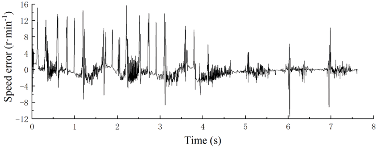
Figure 10: The speed synchronization error of motors
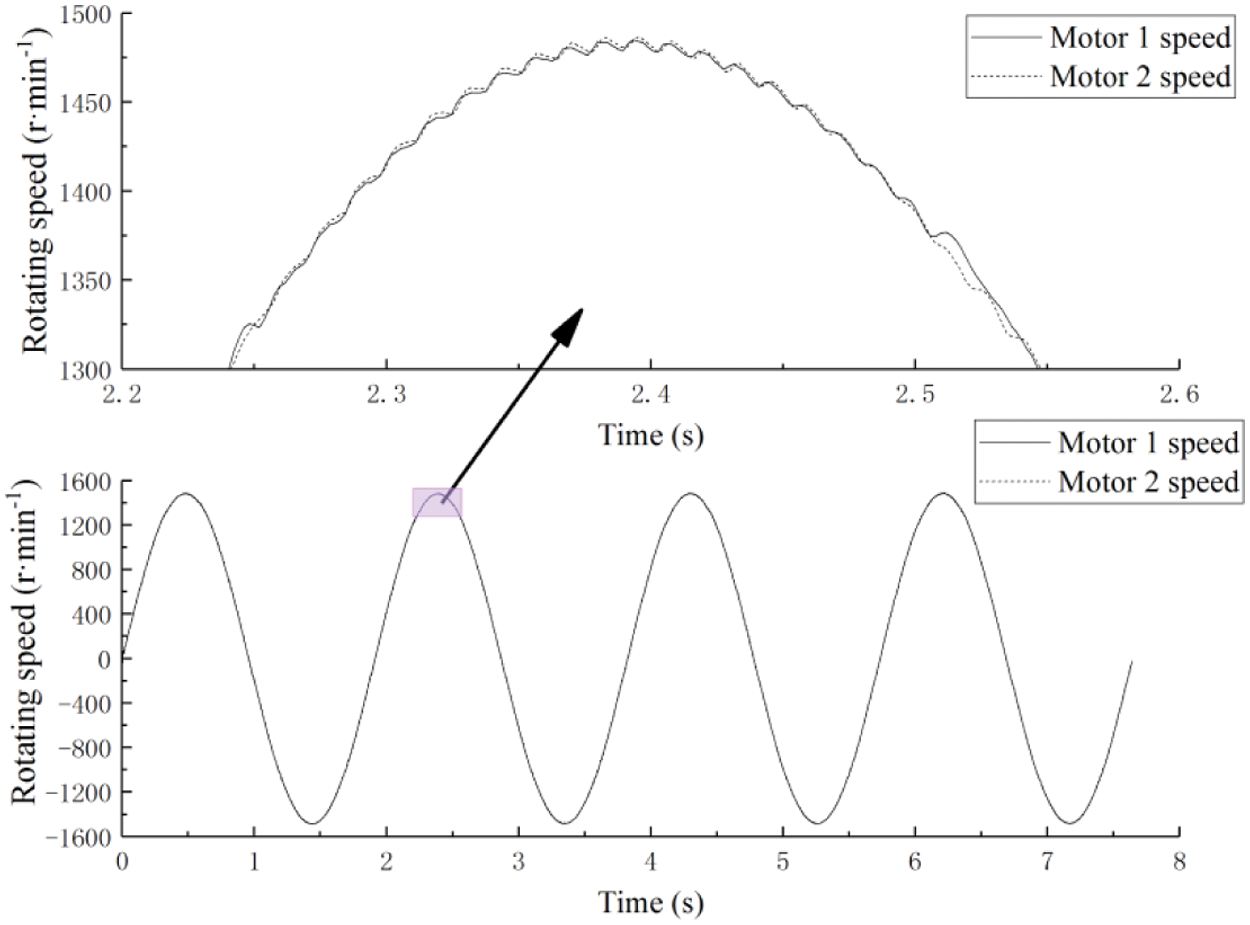
Figure 11: The displacement curves of two actuators
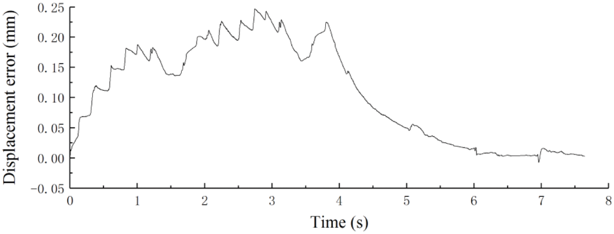
Figure 12: The synchronization error curves of the two actuators’ displacement
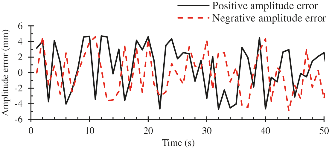
Figure 13: Peak errors of the blade amplitude for a given range of time
A fatigue test for wind turbine blades driven by dual-actuators was designed based on a cross-coupling control strategy integrating ADRC algorithm, conclusions can be drawn as follows:
1) When a fatigue test drive by dual-actuator was under the virtual spindle synchronous control mode commonly applied in synchronous control, the synchronous effect of the two actuators was undesirable.
2) When a fatigue test drive by dual-actuator was conducted in a cross-coupled control mode based on the ADRC algorithm, the speeds of two motors and the displacements of two actuators could be better following the control signal in sinusoidal law stably. The maximum displacement synchronization error was approaching zero. The synchronous effect of the two actuators was satisfactory.
3) The dual-actuator driving system can solve the problem of insufficient loading power of a longer blade. Under the reasonable control method, the blade can meet the amplitude of the blade.
4) The results of the fatigue test proved that the dual-actuator loading system developed in this article maintained the wind turbine blade’s amplitude error at less than 5 mm. Thus, an effective dynamic test method for the fatigue test of a wind turbine blade was provided.
Acknowledgement: The experiment was carried out in conjunction with Lianyungang Zhongfu Lianzhong Composites Group Co., Ltd.
Funding Statement: This research was funded by the National Key R&D Program of China, Grant No. 2018YFB1501203. Meanwhile, this research was funded by the Natural Science Foundation of Shandong, Grant No. ZR2019MEE076. And the work in this paper has partly received funding from the National Key R&D Program of Shandong, Grant No. 2019GGX104001.
Conflicts of Interest: The authors declare that they have no conflicts of interest to report regarding the present study.
1. Chen, X. (2019). Experimental observation of fatigue degradation in a composite wind turbine blade. Composite Structures, 212(4), 547–551. DOI 10.1016/j.compstruct.2019.01.051. [Google Scholar] [CrossRef]
2. Samborsky, D., Mandell, J., Miller, D. (2012). The SNL/MSU/DOE fatigue of composite materials database: Recent trends. AIAA/ASME/ASCE/AHS/ASC Structures, Structural Dynamics & Materials Conference, Honolulu. [Google Scholar]
3. Lee, H. G., Lee, J. (2018). Measurement theory of test bending moments for resonance-type fatigue testing of a full-scale wind turbine blade. Composite Structures, 200(1/3), 306–312. DOI 10.1016/j.compstruct.2018.05.054. [Google Scholar] [CrossRef]
4. Nijssen, R. P. L. (2006). Fatigue life prediction and strength degradation of wind turbine rotor blade composites (Ph.D. Thesis). Delft University the Netherlands, Delft. [Google Scholar]
5. Farinholt, K. M., Taylor, S. G., Park, G., Ammerman, C. M., Farinholt, K. et al. (2012). Full-scale fatigue tests of cx-100 wind turbine blades. Part I: Testing. Proceedings of SPIE-The International Society for Optical Engineering, 8343, 21. DOI 10.1117/12.917493. [Google Scholar] [CrossRef]
6. Greaves, P. R. (2013). Fatigue analysis and testing of wind turbine blades. Durham University, UK. [Google Scholar]
7. Lee, H. G., Park, J. (2016). Static test until structural collapse after fatigue testing of a full-scale wind turbine blade. Composite Structures, 136, 251–257. DOI 10.1016/j.compstruct.2015.10.007. [Google Scholar] [CrossRef]
8. Lee, H. G., Park, J. (2016). Optimization of resonance-type fatigue testing for a full-scale wind turbine blade. Wind Energy, 19(2), 371–380. DOI 10.1002/we.1837. [Google Scholar] [CrossRef]
9. Verma, A. S., Vedvik, N. P., Gao, Z. (2019). A comprehensive numerical investigation of the impact behaviour of an offshore wind turbine blade due to impact loads during installation. Ocean Engineering, 172, 127–145. DOI 10.1016/j.oceaneng.2018.11.021. [Google Scholar] [CrossRef]
10. Verma, A. S., Jiang, Z., Vedvik, N. P., Gao, Z., Ren, Z. (2018). Impact assessment of a wind turbine blade root during an offshore mating process. Engineering Structures, 180(1), 205–222. DOI 10.1016/j.engstruct.2018.11.012. [Google Scholar] [CrossRef]
11. Chen, X. (2017). Experimental investigation on structural collapse of a large composite wind turbine blade under combined bending and torsion. Composite Structures, 160, 435–445. DOI 10.1016/j.compstruct.2016.10.086. [Google Scholar] [CrossRef]
12. Toft, A., Roe-Poulsen, B., Christiansen, R., Knudsen, T. (2016). Design of linear control system for wind turbine blade fatigue testing. Journal of Physics: Conference Series, 753(5), 052023. DOI 10.1088/1742-6596/753/5/052023. [Google Scholar] [CrossRef]
13. Sun, C., Jahangiri, V. (2018). Bi-directional vibration control of offshore wind turbines using a 3D pendulum tuned mass damper-sciencedirect. Mechanical Systems and Signal Processing, 105(9), 338–360. DOI 10.1016/j.ymssp.2017.12.011. [Google Scholar] [CrossRef]
14. Zhang, X., Gao, Z., Yue, H., Cui, S., Wen, B. C. (2019). Stability of a multiple rigid frames vibrating system driven by two unbalanced rotors rotating in opposite directions. IEEE Access, 7, 123521–123534. DOI 10.1109/ACCESS.2019.2937466. [Google Scholar] [CrossRef]
15. Huang, X., Zhang, L., Yuan, G., Wang, N. (2015). Coupling mechanism of dual-excitation fatigue loading system of wind turbine blades. Journal of Vibroengineering, 17(5), 2624–2632. [Google Scholar]
16. Liu, Z., Gao, C., Jing, W. (2021). Dynamic analysis and coupling control of underactuated flight vehicles with single moving mass. Aerospace Science and Technology, 116(5), 106854. DOI 10.1016/j.ast.2021.106854. [Google Scholar] [CrossRef]
17. Snowberg, D., Hughes, S. (2017). Blade testing equipment development and commercialization: Cooperative research and development final report, CRADA number crd-09-346. Proceedings of Industrial and Commercial Applications of Smart Structures Technologies, vol. 8343. San Diego, California, USA. [Google Scholar]
18. Hughes, S., Musial, W., White, D. (2010). Dual-axis resonance testing of wind turbine blades. WO2009097049A2. [Google Scholar]
19. Post, N. L. (2016). Fatigue test design: Scenarios for biaxial fatigue testing of a 60-meter wind turbine blade. Report No. NREL/TP-5000-65227. National Renewable Energy Laboratory. [Google Scholar]
20. White, D., Desmond, M., Gowharji, W., Beckwith, J. A., Meierjurgen, K. J. (2011). Development of a dual-axis phase-locked resonant excitation test method for fatigue testing of wind turbine blades. Asme International Mechanical Engineering Congress & Exposition, 54907, 1163–1172. DOI 10.1115/IMECE2011-63724. [Google Scholar] [CrossRef]
21. Eder, M. A., Belloni, F., Tesauro, A., Hanis, T. (2016). A multi-frequency fatigue testing method for wind turbine rotor blades. Journal of Sound and Vibration, 388(2), 123–140. DOI 10.1016/j.jsv.2016.10.032. [Google Scholar] [CrossRef]
22. Lanzafame, R., Messina, M. (2010). Horizontal axis wind turbine working at maximum power coefficient continuously. Renewable Energy, 35(1), 301–306. DOI 10.1016/j.renene.2009.06.020. [Google Scholar] [CrossRef]
23. Dreidy, M., Mokhlis, H., Mekhilef, S. (2017). Inertia response and frequency control techniques for renewable energy sources: A review. Renewable & Sustainable Energy Reviews, 69(3), 144–155. DOI 10.1016/j.rser.2016.11.170. [Google Scholar] [CrossRef]
 | This work is licensed under a Creative Commons Attribution 4.0 International License, which permits unrestricted use, distribution, and reproduction in any medium, provided the original work is properly cited. |