| Energy Engineering |
DOI: 10.32604/ee.2022.020304
ARTICLE
Experimental Investigation on Prototype Latent Heat Thermal Battery Charging and Discharging Function Integrated with Solar Collector
1Department of Mechanical Engineering, Faculty of Engineering, University of Malaya, Kuala Lumpur, 50603, Malaysia
2Center of Advanced Materials, Faculty of Engineering, University of Malaya, Kuala Lumpur, 50603, Malaysia
*Corresponding Author: Hendrik Simon Cornelis Metselaar. Email: h.metselaar@um.edu.my
Received: 16 November 2021; Accepted: 29 November 2022
Abstract: This paper reports the performance investigation of a newly developed Latent Heat Thermal Battery (LHTB) integrated with a solar collector as the main source of heat. The LHTB is a new solution in the field of thermal storage and developed based on the battery concept in terms of recharge ability, portability and usability as a standalone device. It is fabricated based on the thermal battery storage concept and consists of a plate-fin and tube heat exchanger located inside the battery casing and paraffin wax which is used as a latent heat storage material. Solar thermal energy is absorbed by solar collector and transferred to the LHTB using water as Heat Transfer Fluid (HTF). Charging experiments have been conducted with a HTF at three different temperatures of 68°C, 88°C and 108°C and three different flow rates of 30, 60 and 120 l/h. It is followed by discharging experiments on fully charged LHTB at three different temperatures of 68°C, 88°C and 108°C using HTF at three different flow rates of 30, 60 and 120 l/h. It is found that both higher HTF inlet temperature and flow rate have a positive impact on stored thermal energy. However, charging efficiency was decreased by increasing the HTF flow rate. The highest charging efficiency of 29% was achieved using HTF of 108°C at a flow rate of 30 l/h. Most of paraffin melted in this case, while part of the paraffin remained solid in other experiments. On the other hand, the results from discharging experiments revealed that both recovered thermal energy and recovery efficiency increased by either increasing the LHTB temperature or HTF flow rate. Highest recovered thermal energy of 5,825 KJ at 35% recovery efficiency achieved at LHTB of 108°C using 120 l/h of HTF.
Keywords: Latent heat thermal battery; phase change materials; solar thermal; latent heat storage; thermal battery; thermal storage
Nowadays, limitation of energy resources, uneven distribution of energy resources across the globe and global energy demands are the biggest barriers against the current technology development. Energy conversion and storage are of great importance in most of the technologies [1–5]. A solar water heater is one of the main solar thermal applications, which plays significant role in the solar energy development across the globe. One of the most common solar water heater technique in building sector is evacuated tube solar collector with the predominant global share of 70% with the capability of 340 Giga Watt thermal energy production in 2018 [6–10]. Beside heat collection, the heat storage, timewise extraction and usage of the heat are some of the main issues in solar thermal energy applications. As solar radiation is only available during day time and clear sky, the continuation of solar thermal usage is challenging factor for consideration. Sensible heat storage material has low heat storage capability and continuous heat release over a broad range of temperature range. The latent heat storage technique is a more sustainable and feasible solution than sensible heat storage due to the ability of storing larger amounts of heat for a longer time. Therefore, latent heat storage materials, also known as Phase Change Materials (PCMs), form an alternative solution for thermal energy storage [11–16].
Several researches have been done to integrate the PCMs with the solar collector systems which the focus was more on integrating the PCM with the water storage tank [17–28]. Recently, Naghavi et al. [29] investigated the performance of a new thermal battery as part of an evacuated tube solar collector. In this design, the solar collector tank transformed to the thermal battery by designing a new fins attached to the condenser end and filing the collector compartment with PCM. It was confirmed that this design is able to provide hot water for residential building in tropical climate. They also developed a respective theoretical model [30] which confirmed that this design works properly as a complementary part of evacuated solar collector to produce hot water at times with weak solar radiation. It also showed that the performance of this design is less sensitive to the draw off water flow rate compare to a conventional system.
Even though other researchers were worked on the thermal energy storage, very few researchers were reported about the standalone portable latent heat battery which is designed to integrate with solar collector as a main source of heat. By considering all above-mentioned gaps, the author innovated the state-of-the-art Latent Heat Thermal Battery (LHTB) as a novel solution in thermal energy storage field. There are highlighted advantages of this innovation compare to the other existing lab scale models or actual scale equipment. This simple design can revolutionize the application of a standalone portable thermal battery in residential and industrial sectors. This can be installed anywhere for the charging and discharging purpose or even charge it in one place, then move it to the other place for extracting the stored heat. This device can be connected to a solar collector such as experimental set-up in this study for domestic application, or adopting the design for using industrial heat waste for different range of end users. Design simplicity makes it favorable for adoption with any source of thermal energy for a wide range of applications.
In general, term “thermal battery” is used in literature for any equipment which is able to store thermal energy and release it with delay. Thermal battery concept in solar thermal system is used to improve the thermal storage capability of solar collector and extending hot water supply duration to the night time. In a simple word, storing more amount of thermal energy for a longer time. Obviously, in most of the cases, PCM used as a supplemental part of the solar system in order to improve the system functionality, such as using PCM in flat plate solar collector [31–33], evacuated tube solar collector [34], or water tank [35,36]. In one of the most recent works in this field, PCM was applied in tankless domestic solar water heater in real working condition. Naghavi et al. [11,29] designed and experimentally tested a solar collector thermal battery. In this design, an array of evacuated tube heat pipe solar collectors connected to a manifold filled with PCM. The condenser side of the heat pipe located inside the latent heat manifold which is filled with PCM. The heat pipe condenser-end and the water pipe inside the manifold occupied with fins to improve the heat transfer function. The results from the experimental test in various conditions revealed that this solar collector thermal battery is able to provide the demanded hot water for household in a tropical climate region. The main objective of this study was to design a compact solar water heater with the ability of extending the hot water availability to the time when the solar energy is not available. Theoretical model analysis of the same work [30] shows that the thermal performance of this new design is higher than the similar system without latent heat storage. This is one of the great works in this field which resulted to the innovation of a new type of solar collector. However, as explained, this is a solar collector topic with the extendable thermal battery function.
In this study, the main objective is to design a “thermal battery” as a standalone equipment which can function independently using different source of thermal energy such as solar energy and industry heat waste. One of the highlighted capability of the proposed design is the ability of charging the battery at one place and using the stored heat at different place during discharging function. Unlike the existing works which focus on improving the performance or functionality of the existing devices such as solar collector, the present study focuses on real “thermal battery” device. The modern life is changing very fast and it is predictable to have a demand of thermal battery device in the market as a mobile hot water producer. Electric power bank is a great example which the application turns from an unnecessary device to the essential part of our modern life within a decade. LHTB is highly recommended for remote and rural area as well, specifically where the installation of individual solar collector is not financially possible. Therefore, installation of central solar collector bank with the capability of thermal battery connection for charging process is a brilliant application. The charged LHTB can be collected by individuals and used to produce hot water in their house or work place. This device can also be adopted for using other source of thermal energy such as industrial or residential heat waste. These are the main difference between this study and the other works in the field of thermal battery.
The conceptual design of the LHTB is shown in Fig. 1. It consists of a battery casing which is equipped with a heat exchanger and filled with PCM as a latent heat thermal storage material. The heat exchanger is connected to the HTF stream and feed with water from the solar collector. The heat exchanger is sank in the PCM play a role of heat transfer intermediate device between the HTF and PCM. Heat is transferred from the HTF to the PCM and stored in form of latent heat. In a reverse process, the water from the storage tank is heated up by LHTB and supplied to the end user. This device is designed specifically for residential building for human use.
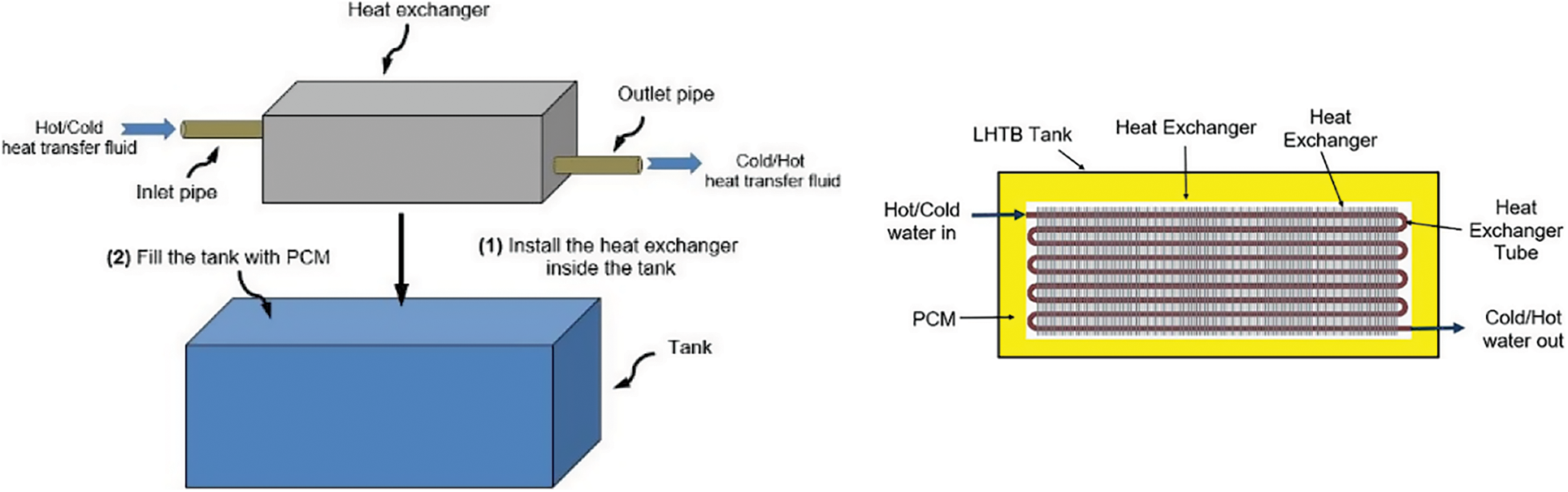
Figure 1: LHTB conceptual design
Experiment design principle is based on three main steps, heat collection from a heat source, heat storage in a thermal battery and heat release to the final user once it is needed. One of the objectives of this study is to integrate the LHTB with solar collector as a main source of heat. The heat should be enough to melt down the PCM and create a potential latent heat storage as a result of PCM phase conversion. Therefore, selection of the solar collector is the first step to design the LHTB.
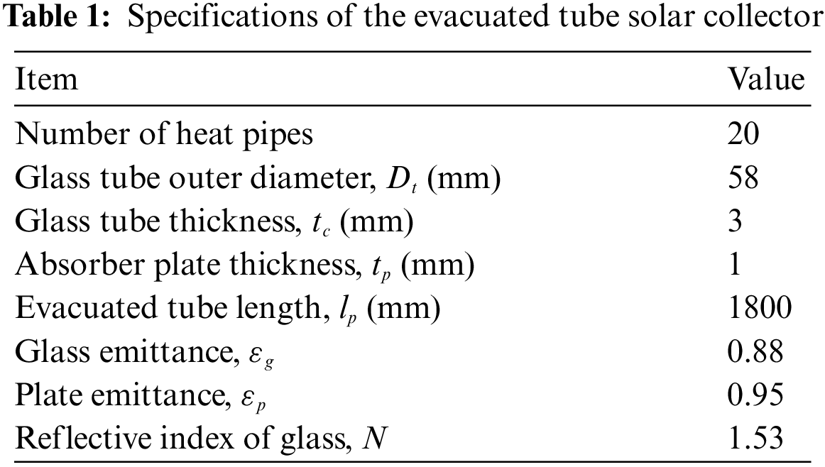
It is very important to determine the heat source in order to calculate the LHTB capacity. Many studies have been done in the field of solar collector types and their performances [37–40]. An Evacuated Tube Solar Collector (ETC) (Thermo Renewable SDN BHD) consisting of 20 tubes was selected. Specifications of the ETC are given in Table 1.
2.2 Desirable Thermal Storage Material (PCM)
Melting point is the first criterion in the selection of a suitable PCM as it must match the operating range of the application. Other considerations are a high heat of fusion and a good thermal conductivity as they allow a large amount of heat to be stored and released without large temperature gradients. Low volume change during phase change, reversible melting and solidification behavior, long term reliability during repetitive cycling, low vapor pressure, nontoxic and low cost are also desirable. Based on the literature and taking all above considerations into account, the most suitable PCM for a final consumer temperature of 39°C is paraffin wax with a melting temperature of around 60°C. Paraffin is a white, odorless, tasteless and waxy organic material. Table 2 shows the thermophysical properties of the selected paraffin. The selected paraffin melting range is between 55°C and 64°C as confirmed by DSC (Differential Scanning Calorimeter) test. The other important factor for designing the LHTB is the thermal expansion of PCM within the temperature range of experiments. DSC and thermal expansion coefficient of paraffin is stipulated in Fig. 2.
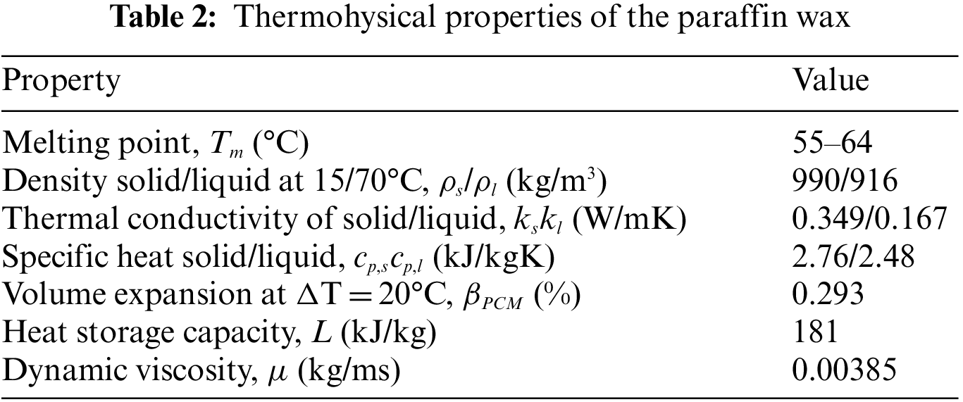
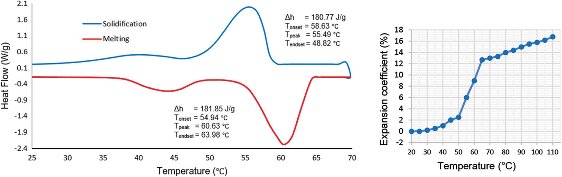
Figure 2: DSC and expansion coefficient of the paraffin wax
The LHTB casing is designed for outdoor application and must hold the weight of paraffin and heat exchanger. Prevention of paraffin leakage as well as accommodation of thermal expansion were taken into account. Based on meteorological data taken at Kuala Lumpur International Airport, the average solar radiation in Malaysia is about 4.5 kWh/day per square meter. Based on the literature, solar collector manufacturer data, solar collector surface, average ambient temperature of 30°C, and paraffin temperature of 64°C in fully liquefied form, the required amount of paraffin was 46 kg. As a result, the LHTB casing design is based on a volume of 0.0719 m3, as shown in Fig. 3.
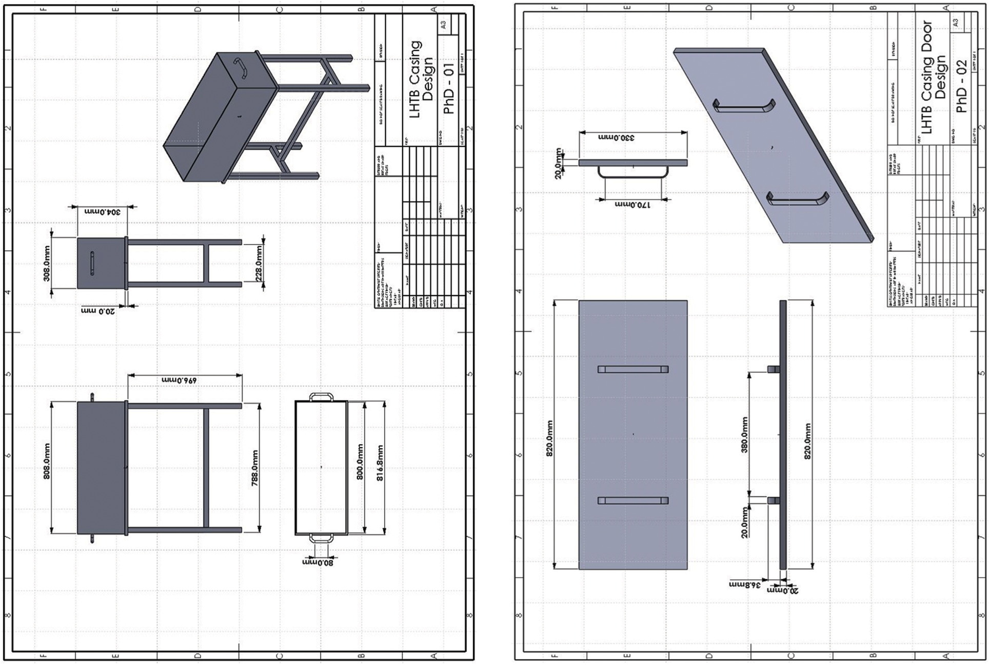
Figure 3: LHTB casing design
The LHTB heat exchanger design and performance depend on heat exchanger type, number of tubes and passes, fin specification and the material of construction. Compact heat exchangers have a large heat transfer surface area per unit volume of the heat exchanger. As the fluid outside the tube is in static condition, fins are necessary for heat transfer from hot to cold medium and vice versa. Therefore, the model is designed based on the tube-fin heat exchanger having continuous fins made from aluminum which is also called plate-fin and tube heat exchanger. Design specifications and LHTB 3D model are shown in Fig. 4.
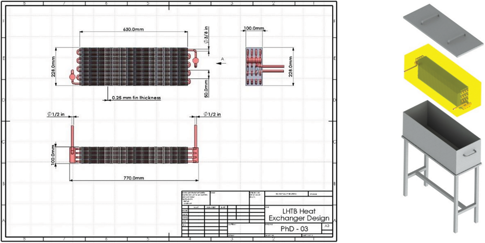
Figure 4: Heat exchanger design & LHTB 3D model
3.1 LHTB Fabrication & Experimental Set-up
LHTB prototype is fabricated and shown in Fig. 5. Fifteen thermocouples inside the LHTB are arranged in three layers parallel to the heat exchanger surface record the PCM temperature profile during experiments. Thermocouples are placed in the connecting pipes to measure the HTF temperature in each section. The experimental set-up is built at the rooftop of the Faculty of Engineering in the University of Malaya at a latitude and longitude of 3.1° N and 101.4° E, respectively. The tests are conducted on sunny days.
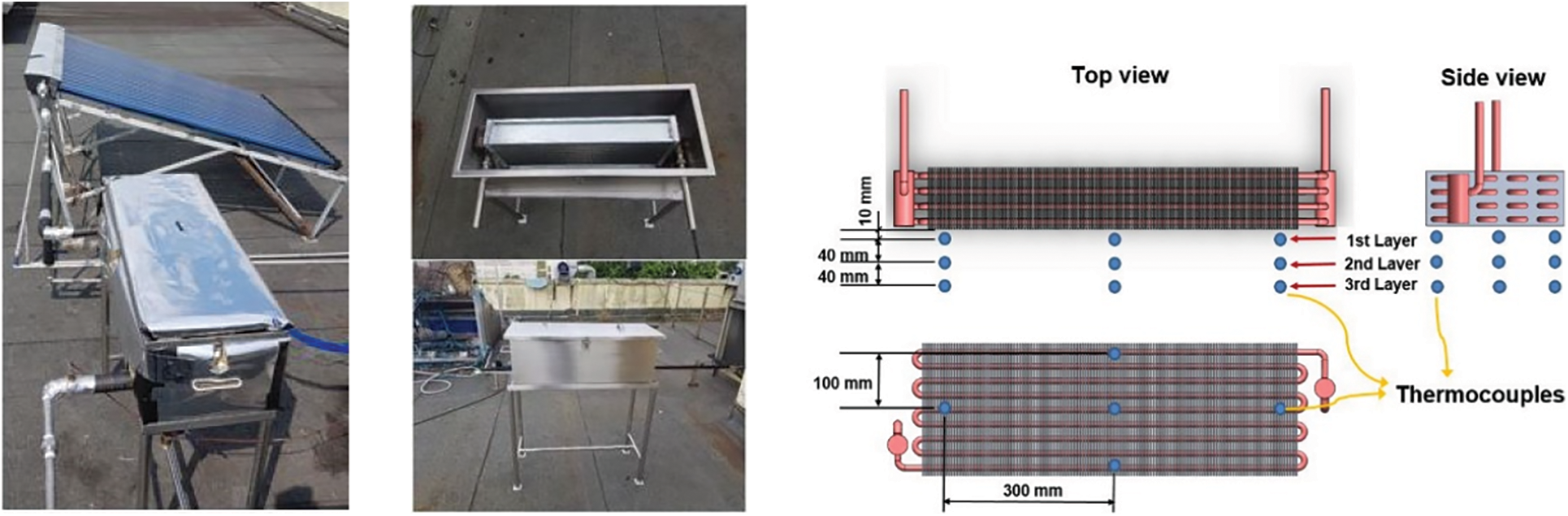
Figure 5: Photos of fabricated LHTB and position of thermocouples
The schematic diagram of the experimental set-up is presented in Fig. 6. It consists of solar collector to absorb hot from the sun, LHTB as the thermal battery, tank to store the HTF, magnetic pump to flow the HTF and needle valve to adjust the flow as the main components. The set-up is equipped with instruments for data operating parameters measurement and recording included data logger GL820 made by Graphtec, digital flowmeter S030 manufactured by Burkert and T type thermocouples with measurement accuracy of ±0.1% of reading ±0.5◦C, ±0.2%, and ±0.5◦C/0.4% whichever is greater, respectively. The LHTB was insulated using 50 mm rock-wool on all sides as well as covered with aluminum plate to minimize the heat loss. Connecting pipes were insulated using 10 mm prefabricated thermal insulation.
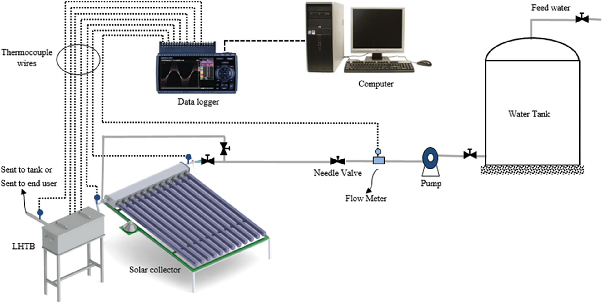
Figure 6: Schematic diagram of LHTB experimental set-up
The experiment tests are carried out in charging and discharging modes. During charging mode, the HTF is pumped from the storage tank and pass through the solar collector. The heat is absorbed by the solar collector and transferred to the LHTB using the HTF. The HTF pipe which bypasses the solar collector is used to adjust the HTF temperature entering the LHTB. At this time, the heat transfers from HTF to the paraffin via the heat exchanger, the solid paraffin melts down and the heat stores in forms of latent and sensible heat in the paraffin. The outlet water becomes colder as a result of transferring heat to the paraffin. This process continuous for a course of four hours. Discharging tests are carried out using water as a HTF at ambient temperature and pump it directly to the LHTB. During the tests, the outlet water gets warm as a result of heat transfer from the liquid paraffin and the liquid paraffin becomes colder which finally transforms to the solid phase. The experiment stops once the water output temperature reaches the design temperature of 39°C.
3.3 LHTB Efficiency Calculation
The LHTB charging efficiency, ηc, is defined as the total thermal energy absorbed by the LHTB at the end of each charging test divided by the total thermal energy entering the LHTB during the test as below:
where qa is the total absorbed thermal energy and qi is the total thermal energy input during the experiment. qa can be calculated using the following equations and it is integrated over the duration of the experiment:
where q is the sensible heat [kJ], m is the mass of substance [kg], Cp is the specific heat [kJ/kg.°C], and ΔT is the change in temperature [°C]. The LHTB recovery efficiency, ηc is calculated for discharging modes based on the following formula:
where the qr is the total recovered thermal energy from the LHTB and it is calculated using recorded data and qe is the maximum extractable thermal energy at the same testing condition.
There are two source of error in different instruments may affect the result of experiment data; random and systematic errors. Therefore, the uncertainty analysis was performed to estimate the maximum possible error from the experiment [41,42]. The sources of the errors in different instruments are affected by two factors, systematic errors (i.e., individual instrument uncertainty, calibration, and data acquisition errors) and random errors.
where, Ut is the total uncertainty, εs and εr are the systematic and random errors, respectively, which can be calculated by:
where, n is the error source number. The error εr,i can be calculated by:
where N is the number of times a parameter is measured and
Therefore, the uncertainty of this experiment is mainly a function of the following parameters:
The calculated random error for TL1, TL2, TL3, THTF-in and THTF-out are 0.474°C, 0.564°C, 0.575°C, 1.015°C and 0.709°C, respectively. The systematic error of thermocouples and flowmeter is ±0.1% of reading ±0.5°C and ±0.2%, respectively. Based on the proposed uncertainty analysis method, the total uncertainty was found at 3.48%.
Charging tests were conducted using steady state HTF inlet temperature of 68°C, 88°C and 108°C. Each series of tests were repeated for three HTF flow rate of 30, 60 and 120 l/h. Discharging tests were carried out for fully charged LHTB at three different temperature of 68°C, 88°C & 108°C and three different water consumption of 30, 60 & 120 l/h. The average HTF inlet temperature is 30°C and minimum temperature for water consumption is 39°C. Summary of experimental tests are tabulated in Table 3.
The battery charging function can be evaluated based on the amount of absorbed thermal energy at the end of the test. Fig. 7 depicts the measured paraffin temperature variation with time with a HTF temperature of 68°C and various flow rate of 30, 60 and 120 l/h. The results for the HTF temperature of 88°C and 108°C depict in Figs. 8 and 9. From these figures we can see that during the early stage of the charging process, the heat transmission from HTF inlet to the heat exchanger is mainly consumed to heating up the pipes, heat exchanger and melting the paraffin between the heat exchanger plates until L1. This step takes few minutes depends on the HTF inlet temperature and flow rate. It is followed by a dramatic temperature increase of paraffin in L1 and followed by slower rate in water outlet temperature. This continues until L1 reaches the melting temperature range. During the melting process at L1, the heat is absorbed by the paraffin as latent heat with very less temperature increment. Then the liquid temperature rises more gradually with lower rate compare to the first sensible region at the solid phase. The melting boundary moves from the heat exchanger toward casing wall while the test is progressing. As time progressed, the water outlet temperature approaches L1 temperature and exceeded during the melting process. Once the melting is completed at L1, the temperature difference between L1 and water outlet approaches to zero toward the charging completion.
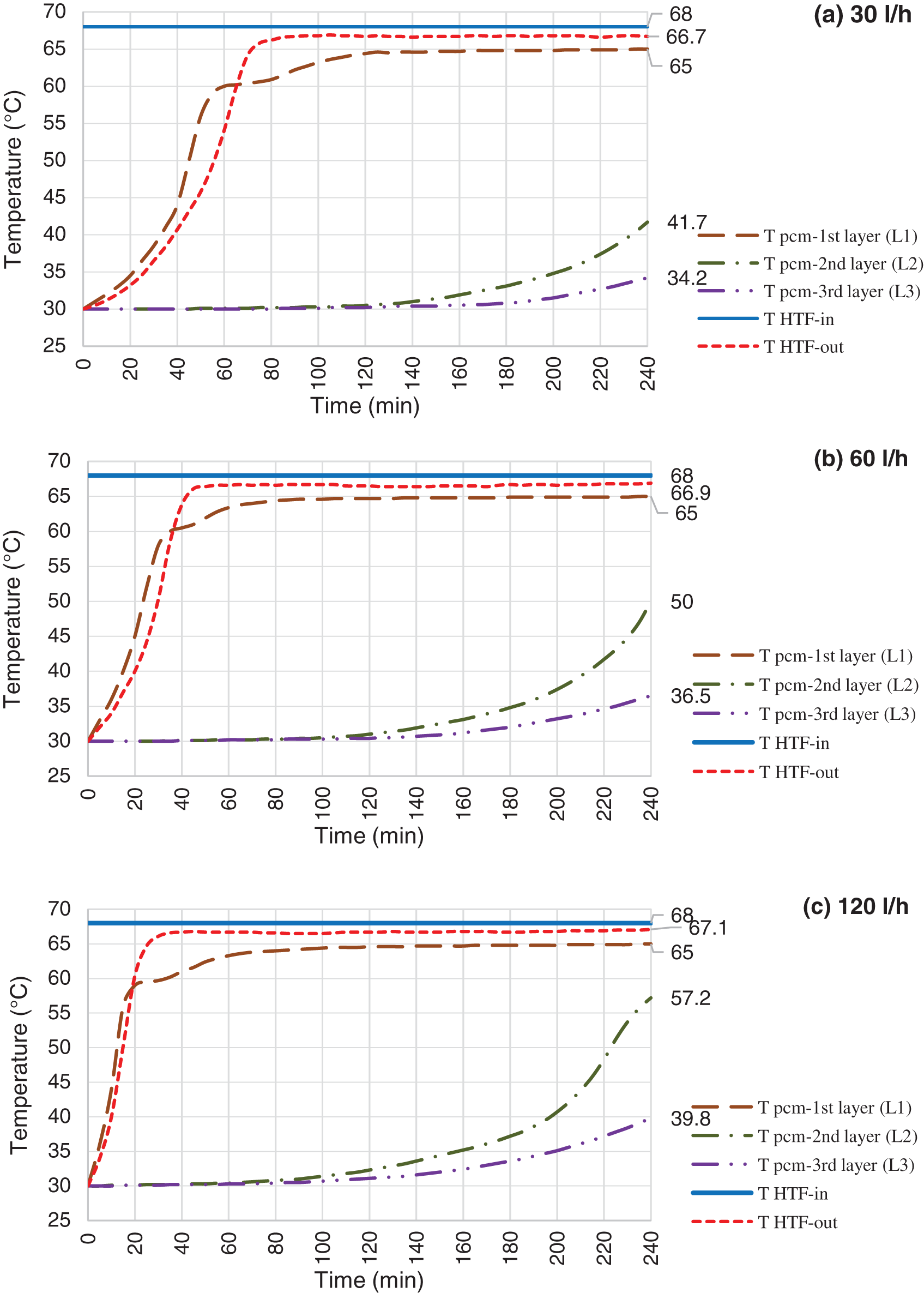
Figure 7: Charging mode, HTF inlet temperature @ 68°C and flow rate @ 30 l/h (a), 60 l/h (b) & 120 l/h (c)
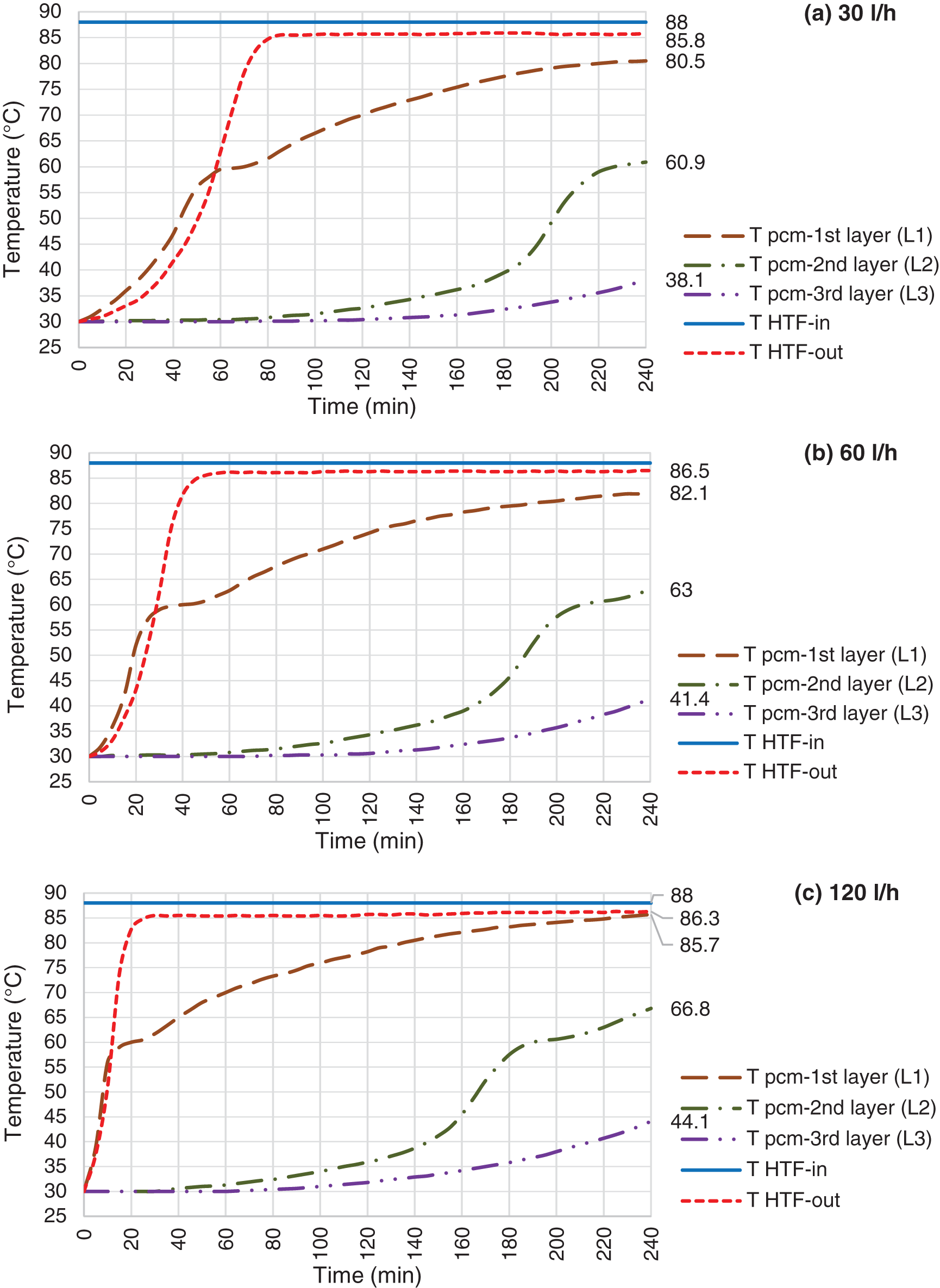
Figure 8: Charging mode, HTF inlet temperature @ 88°C and flow rate @ 30 l/h (a), 60 l/h (b) & 120 l/h (c)
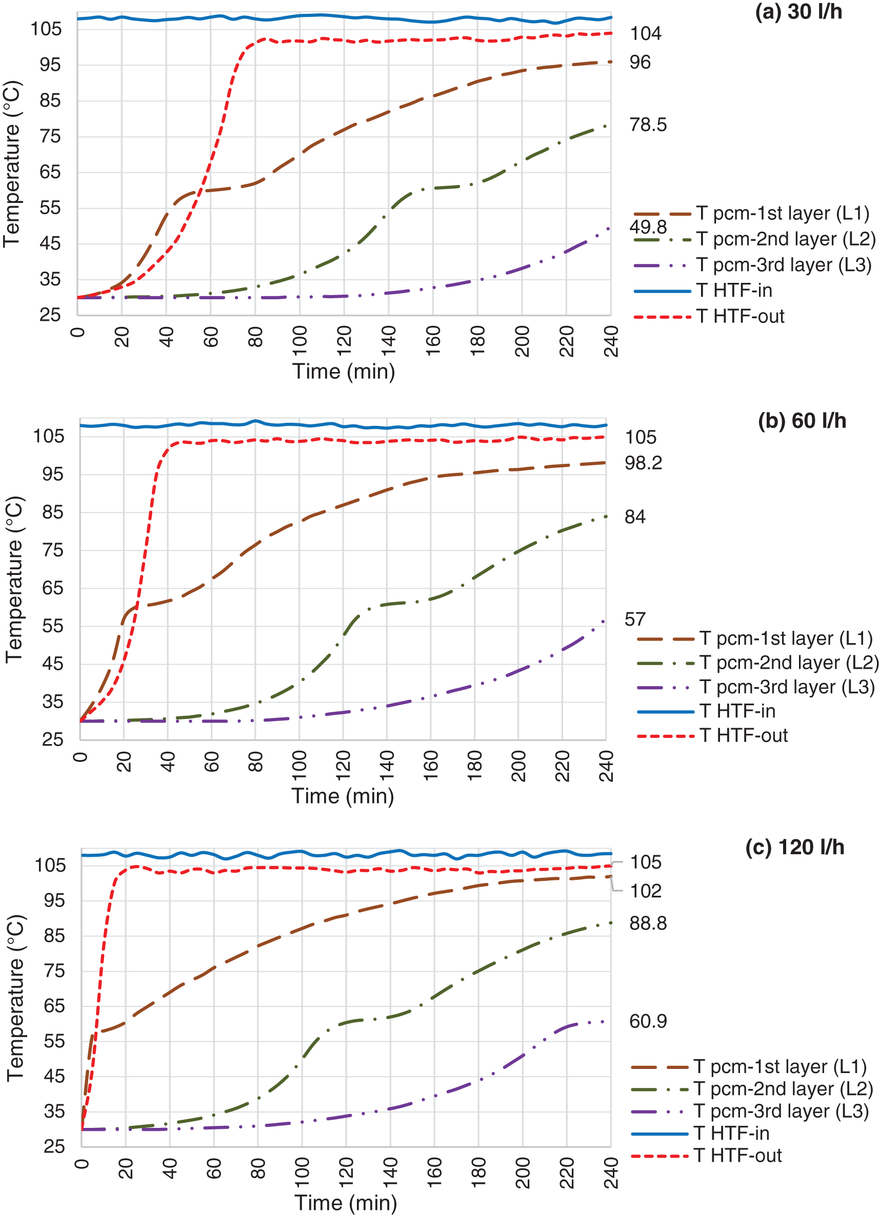
Figure 9: Charging mode, HTF inlet temperature @ 108°C and flow rate @ 30 l/h (a), 60 l/h (b) & 120 l/h (c)
At the beginning of each test, heat transfers via only heat conduction from the heat exchanger to the solid paraffin, where the sensible heat is the only heat storage mode in the solid paraffin. As soon as a thin layer of a liquid paraffin is formed, heat storage in the paraffin undergoes three regions, a sensible region in the liquid section followed by latent region within melting boundary at the range of 55°C–64°C and sensible region in the solid section. Although conduction heat transfer takes place at early stage of charging, it is finally dominated by convection as the melting progresses. As can be seen in Fig. 7, the temperature increases fast with a steep trend in L1. The trend gets steeper as HTF flow rate increases. Therefore, the paraffin reaches the melting point faster, around 20 min for 120 l/h compare to 60 min for 30 l/h. This section of the curve is related to the conduction heat transfer from the HTF to the solid paraffin, where the paraffin temperature increases steeply. When the temperature reaches the melting range, the temperature rises very slowly and transferred heat from HTF absorbs by paraffin as latent heat. This is where the main charging process occurs and huge amount of energy stored in the LHTB. Once the melting process completed at L1, the temperature rises slower compare to the first section with steep temperature rise. This is due to the lower thermal conductivity of paraffin in the liquid than solid form and lower temperature difference compare to the beginning of the test. As can be seen, the water outlet temperature raises by a time delay compare to L1 but exceed L1 at the middle of melting range. Beyond the melting process the rate of HTF outlet temperature increment also slows down. The temperature profile in L2 and L3 is same as L1 which happens in a wider timeline. However, the paraffin is not fully melted in L2 and L3 at all tests. This confirms the charging incompleteness process. In order to improve the gap of remaining solid paraffin, it is recommended to improve the heat exchanger design by extending the fins or distributing the tubes in the whole battery compartment. This will help to harmonize the heat distribution which leads to melt down the whole PCM at the end of the test.
4.1.2 Influences of the HTF Inlet Temperature
As expected, the HTF inlet temperature should have strong influence on charging process. Figs. 7–9 depict the result of various HTF inlet temperature on the paraffin temperature variation and melting progression. Basically, the overall heat transfer coefficient between the HTF and paraffin is constant in all experiments, therefore, the heat flow from HTF to paraffin is directly proportional to the temperature difference between the HTF and paraffin. This can be concluded that the melting process should decrease by increasing HTF inlet temperature. This means that at the same experiment duration, more amount of paraffin shall be melted or higher temperature achieved, in case of using higher HTF temperature. For instance, L2 temperature reached at 50°C, 63°C and 84°C at the tests using 60 l/h of HTF and temperature of 68°C, 88°C and 108°C. This means that, the L2 even not reached the melting range in the test using HTF at 68°C, however, it is fully melted in the test using HTF at 108°C.
4.1.3 Influences of the HTF Flow Rate
Increasing the HTF flow rate will enhance the heat transfer process between HTF and paraffin. Each of the Figs. 7–9 shows the paraffin temperature profile at constant HTF inlet temperature and various flow rate. As flow rate increases, the temperature of paraffin increases faster and causes higher LHTB temperature at the end of the charging process. This means that the HTF flow rate has direct influence on the heat transfer process. From these figures, we can see the flow rate does produce a significant influence on the process, and improve the temperature behavior of the paraffin. In all cases, when the flow rate increases, more amount of paraffin melted in a shorter time which resulted to store more amount of latent heat at the end of the test. Fig. 7 shows the paraffin at L2 only reached to 41.7°C and 50°C for HTF flow rate of 30 and 60 l/h, however, it reached the melting range (57.2°C) at 120 l/h. The same pattern follows for tests using HTF at 88°C (Fig. 8). Lower flow rate of 30 l/h could push L2 to mushy zone (60.9°C), but higher flow rate of 120 l/h pushes L2 beyond melting range to the fully melted phase. For 108°C test (Fig. 9), L3 reached the middle of mushy zone at 60.9°C for HTF of 120 l/h vs. the bellow melting range (57°C) for HTF of 30 l/h. The maximum melting occurs in test using 120 l/h of HTF at 108°C where paraffin at L3 reached the mushy zone at 60.9°C. On the other hand, the least melting happened at test using 30 l/h of HTF at 68°C where the paraffin at L2 only reached to 41.7°C. In overall, charging efficiency increases by increasing the HTF temperature at constant HTF flow rate.
Apparently, the influences of the HTF flow rates are much weaker than the inlet temperature. This is due to the fact that higher flow rate can only improve the convection heat transfer where the thermal resistance of this convection heat transfer is less important than the thermal conduction resistance of the PCM due to the very small thermal conductivity of the PCM.
In order to perform the discharging operation experiments, the paraffin first heated up reaching its uniform temperature. As soon as the whole system was steady, the cold HTF at ambient temperature was started to circulate in the LHTB and the experiment starts. According to the data, the inlet HTF is at ambient temperature between 28.6°C and 31.8°C, depending on the weather condition.
4.2.1 Solidification Curves and Discharging Characteristics
Figs. 10–12 illustrate the temperature profile of paraffin during the solidification process. At the very beginning of the process, there is a peak in HTF inlet temperature which last for few minutes. This is due to the transferred heat from the fully charged LHTB to the inlet pipe via conduction prior starting discharging process. Discharging occurs as a result of temperature difference between the liquid paraffin and HTF. Drastic temperature reduction of paraffin at the beginning of each test represents the sensible heat transfer via convection in the liquid paraffin. Followed by constant temperature that shows latent heat discharge at almost isothermal process. This is the mushy phase of paraffin which is a mixture of the liquid and solid phase. Third section starts from the second drastic temperature reduction to the end of the test which is the indication of sensible heat transfer in the solid phase. All tests ended up with maximum paraffin temperature at 60.6°C which is the indication of remaining latent heat in paraffin. This is due to the solid paraffin formation on the heat exchanger surface which creates a barrier against the heat transfer from the liquid paraffin to the heat exchanger. The battery temperature reduces during the tests followed by warming up the outlet water. However, paraffin at L1 contributes more to the battery productivity than the other layers. This resulted to faster temperature reduction in L1 while paraffin further from the heat exchanger remains above solid paraffin temperature.
4.2.2 Influences of the Inlet HTF Temperature and LHTB Temperature
Once the HTF flow starts, the heat transfers from paraffin and increases the HTF outlet temperature to the highest point. This is followed by reducing the paraffin temperature at all layers drastically. The reason is that the effective conductivity of the liquid paraffin is well enhanced by the natural convection within the paraffin. Temperature profile stabilized during phase transition in all layers. This is followed by drastic reduction of L1 at the end of mushy zone. It means, the paraffin at L1 enters the solid phase where the temperature profile drops dramatically. However, the other layers follow horizontal trend toward the end of the tests. This is where the latent heat remains trapped inside the paraffin. As the solid layer extended on the heat exchanger surface with time, heat resistance increases against the heat transfer from the liquid paraffin to the heat exchanger. The increased solid paraffin and restrained natural convection by diminishing liquid paraffin space will certainly result on increasing the thermal resistance of the process with time. Therefore, the melting boundary moves slower and HTF outlet temperature reduces gradually. As can be seen in Fig. 10a, the L1 enters the solid phase after 40 min from the beginning of discharging test where the temperature reduces drastically. It means that the paraffin between the heat exchanger and L1 is completely solidified. Mushy phase takes around 24 min for L1. Then temperature reduces constantly once solidification completed toward the end of the test at 50.7°C. On the other hand, L2 and L3 remain in the liquid phase at constant temperature of 58.8°C. This is where the paraffin remains in mushy phase at melting range. As it observed at the end of the tests, 8 mm and 15 mm of the solid paraffin formed at the surface of paraffin and LHTB walls, respectively. Heat loss from LHTB outer surfaces is the reason of the solid paraffin formation on the walls. The solid paraffin formation on the heat exchanger surface varies from few millimeters to 22 mm. The solid paraffin thickness is higher at lower LHTB temperature and lower HTF flow rate. At higher HTF flow rate, the rate of the solid formation is more than the rate of heat transfer from the liquid paraffin to the heat exchanger. Therefore, more heat remains in the liquid paraffin at the end of the test. This is one of the gaps which need to be considered for design improvement. Circulating PCM during discharging process and modifying the heat exchanger design to cover the whole battery compartment are suggested for improvement.
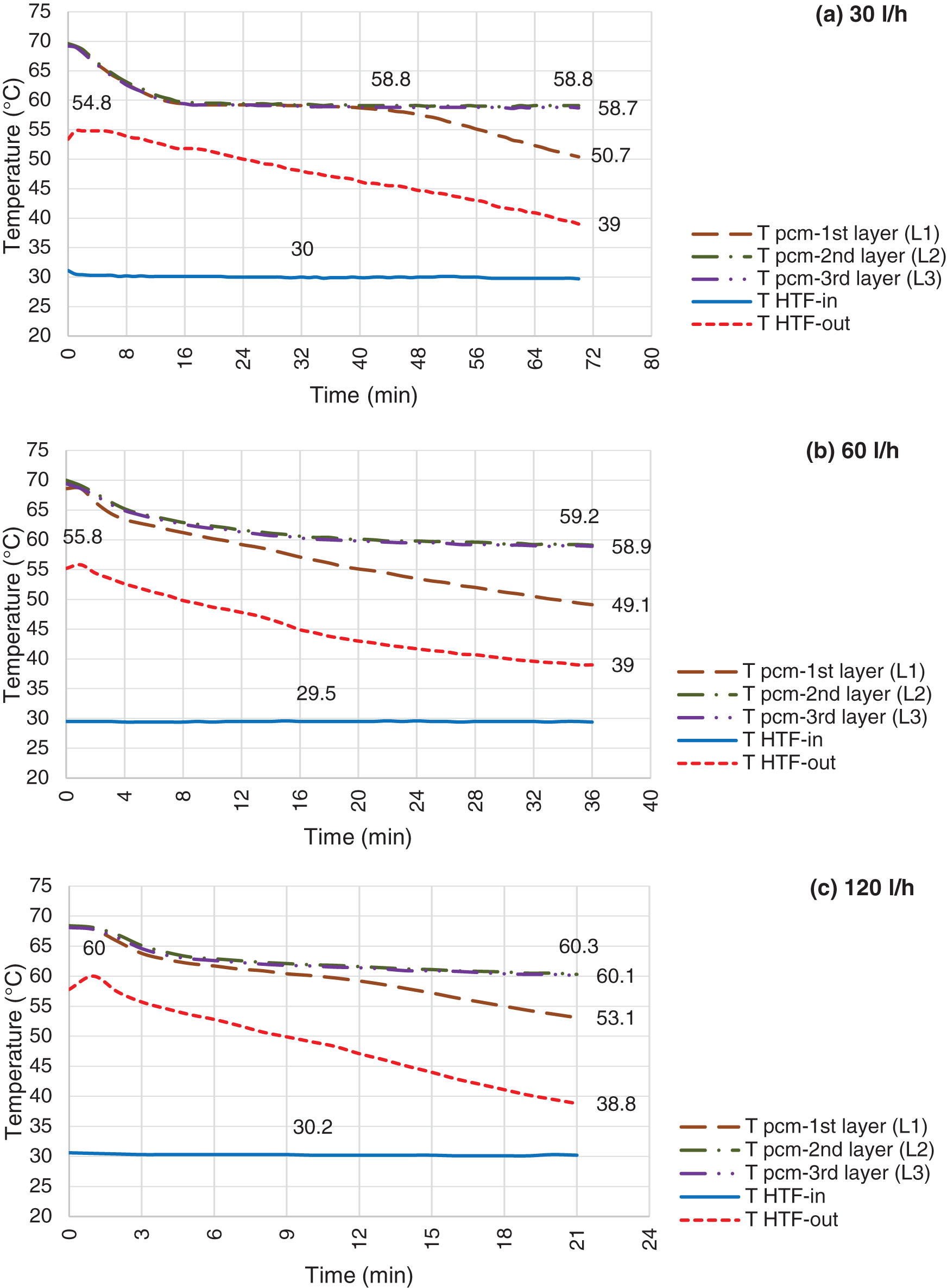
Figure 10: Discharging mode, LHTB fully charged @ 68°C and HTF flow rate @ 30 l/h (a), 60 l/h (b) & 120 l/h (c)
Discharging process for the LHTB at 88°C and 108°C illustrate in Figs. 11 and 12, respectively. Discharging pattern is the same as LHTB at 68°C, however there are differences in terms of discharging duration and solidification. Obviously, as LHTB temperature increases the LHTB delivery time increases as well. However, it is invers in case of increasing HTF flow rate. LHTB productivity decreases by increasing the HTF flow rate. Solidification on the heat exchanger surface is one of the issues during discharging process. Solidification starts from the heat exchanger surface and extends to the LHTB walls. Heat loss from the paraffin to the heat exchanger is faster than the heat convection inside the liquid paraffin. Therefore, paraffin surrounding the heat exchanger solidifies faster which then create a solid layer on the heat exchanger surface. The solid layer acts as a barrier against heat transfer from the liquid paraffin to the heat exchanger. Higher thermal conductivity of the solid paraffin compare to the liquid paraffin is a main factor as well as contribution of static condition of the liquid paraffin which creates poor natural convection. Results in general confirm that by moving toward the end of the tests, the liquid paraffin far from the heat exchanger contributes lesser to the LHTB productivity than paraffin close to the heat exchanger. However, reducing the HTF flow rate can give enough time to the liquid paraffin to transfer more heat to the HTF prior to the solid layer formation on the heat exchanger surface. Lower paraffin temperature at L2 and L3 at the end of the tests confirm this fact. On the other hand comparing the results of discharging in constant flow rate at different LHTB temperature reveals that the final paraffin temperature at L2 and L3 remains the same. But higher LHTB temperature can increase the LHTB productivity. For example tests at constant HTF flow rate of 60 l/h (Fig. 11), show the battery can perform for duration of 46 min at 88°C LHTB compare to 36 min at 68°C LHTB. This confirms the LHTB at higher temperature of charging mode can produce more hot water during discharging process. In another word, it can say that the LHTB in higher temperature has the capability of storing more energy than the LHTB in lower temperature. In overall, it was shown that LHTB is able to deliver water above designed temperature for maximum of 115 min at LHTB of 108°C using 30 l/h of HTF compare to 21 min at LHTB of 68°C using 120 l/h of HTF. Based on the findings during experimental test, it is recommended to work on the paraffin movement during the tests before transfer to the solid phase as a recommendation for heat transfer improvement.
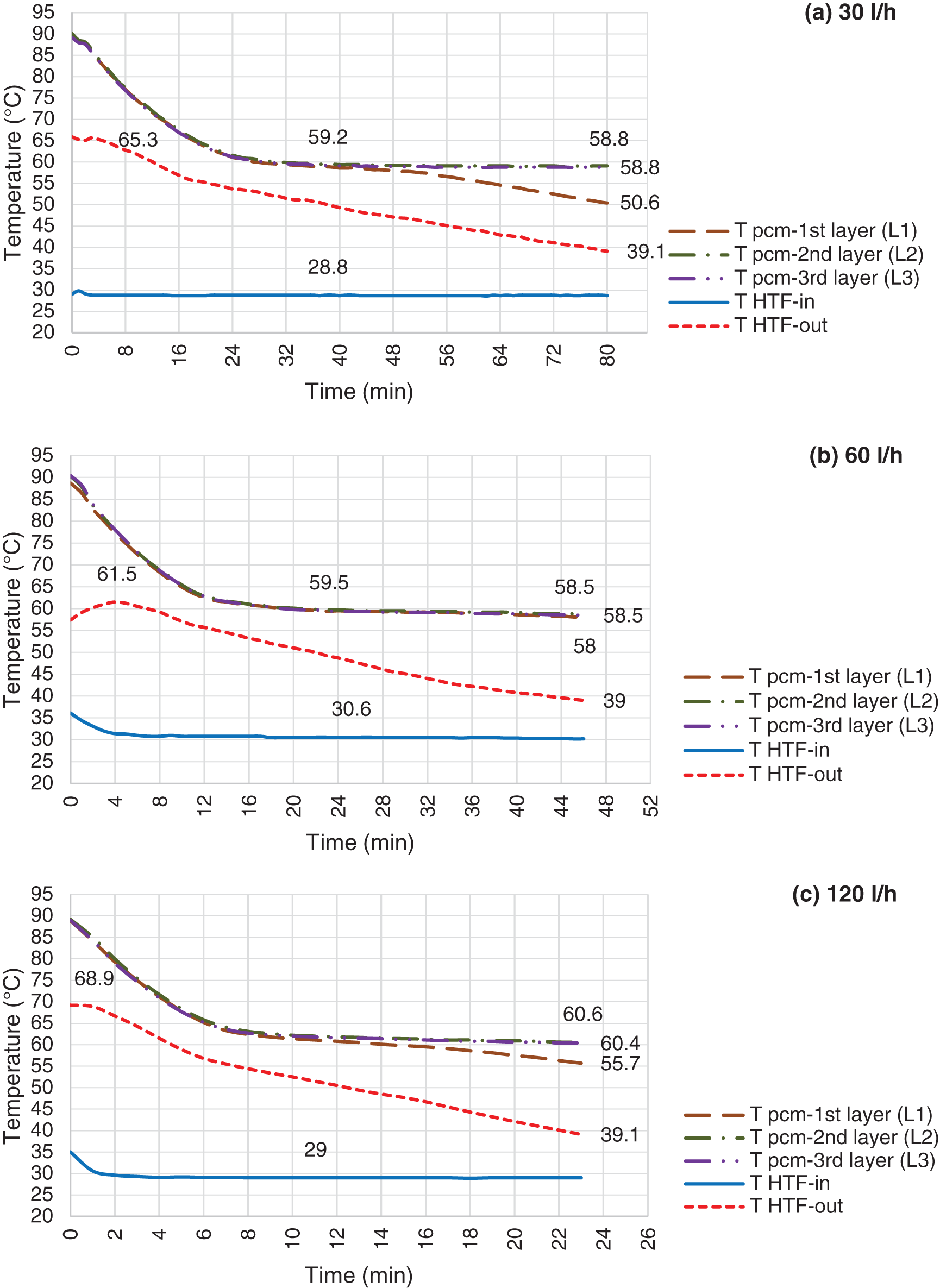
Figure 11: Discharging mode, LHTB fully charged @ 88°C and HTF flow rate @ 30 l/h (a), 60 l/h (b) & 120 l/h (c)
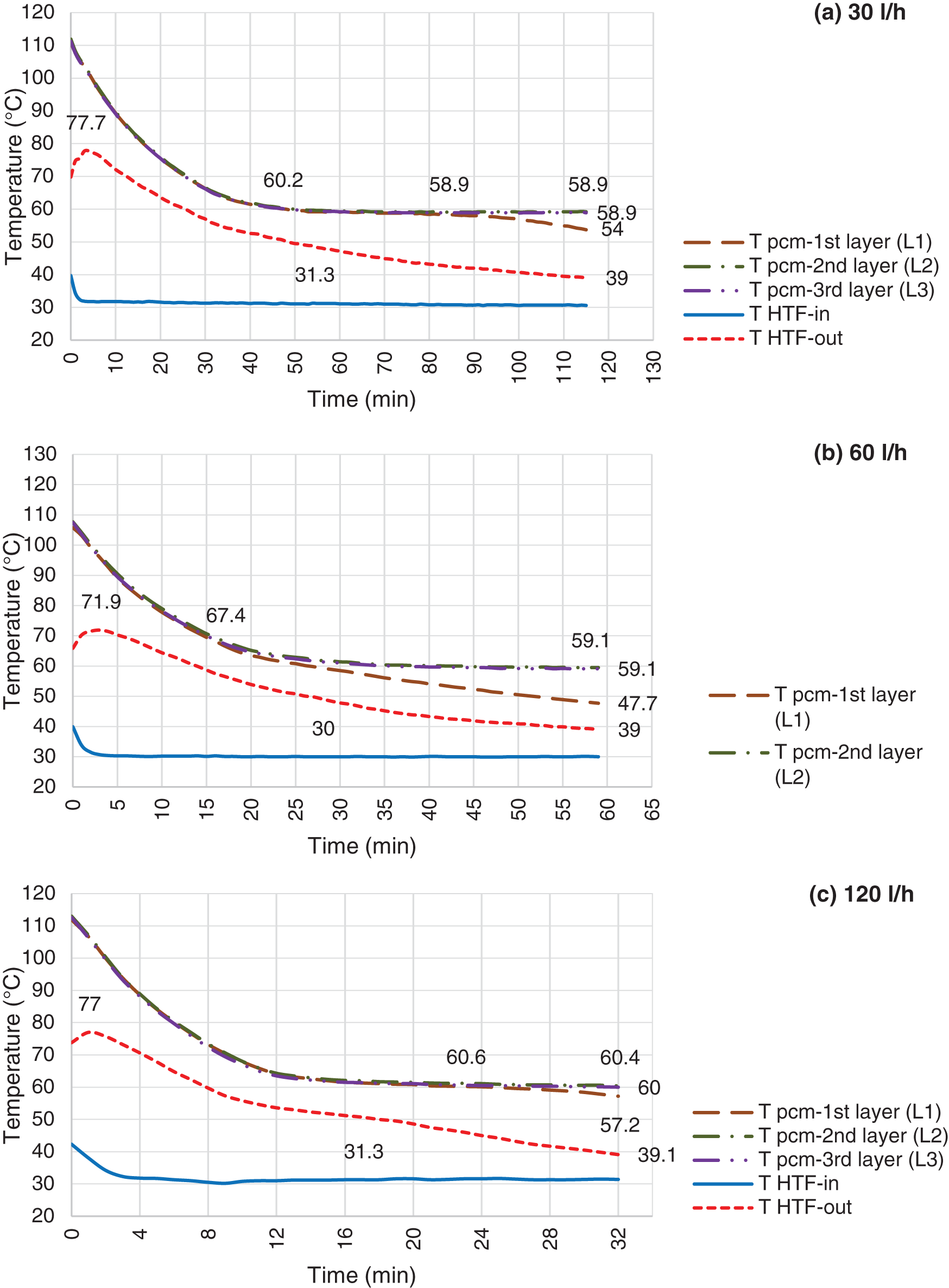
Figure 12: Discharging mode, LHTB fully charged @ 108°C and HTF flow rate @ 30 l/h (a), 60 l/h (b) & 120 l/h (c)
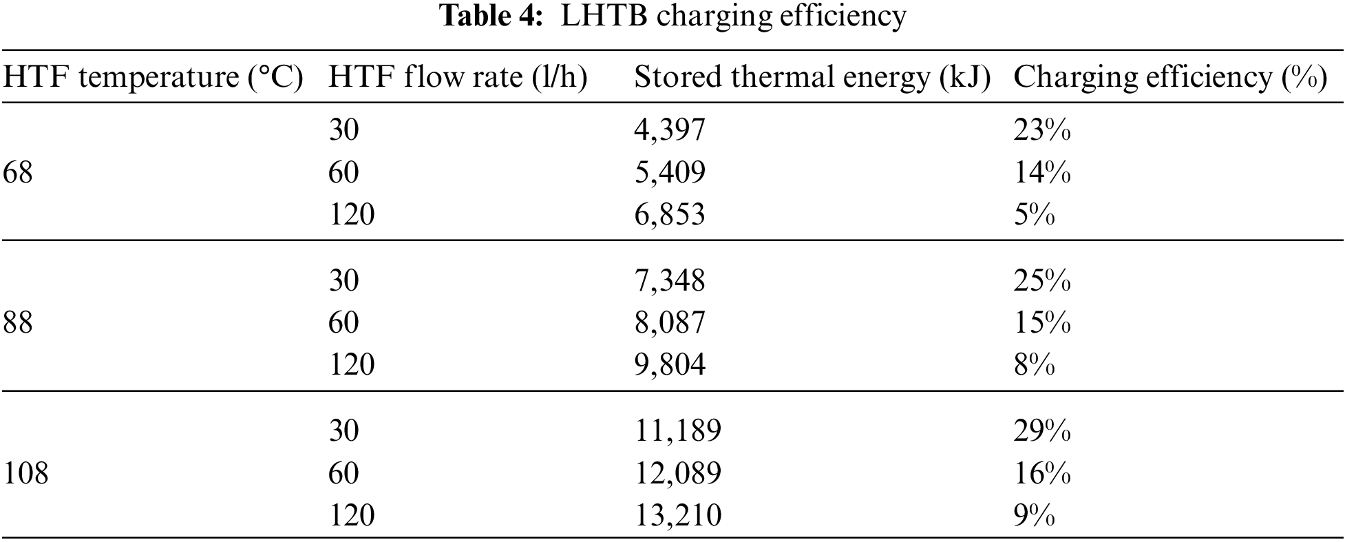
To calculate the performance and efficiency of the LHTB at charging, the molten fraction of the paraffin in the LHTB at the end of the test needs to be determined. The molten fraction can be estimated based on the paraffin final temperature compared to the cool and warm limits of the melting temperature range. Practically it is not possible to accurately determine the amount of liquid and solid paraffin. Therefore, the charging efficiency is calculated based on the energy enter to and exit from the LHTB by HTF using Eq. (1). The result in Table 4 shows that the stored thermal energy increases by increasing the HTF flow rate at constant HTF inlet temperature. However, the efficiency decreases at the same condition. Since the residence time of the HTF in the heat exchanger is shorter, a smaller portion of its heat can be absorbed. On the other hand, both stored thermal energy and charging efficiency increases by increasing the HTF inlet temperature at constant HTF flow rate. The test using HTF inlet temperature at 108°C and flow rate of 30 l/h delivered the highest charging efficiency. While, the test using HTF inlet temperature at 68°C and flow rate of 120 l/h delivered the lowest charging efficiency. On the other hand, the highest amount of thermal energy stored in the test using HTF temperature and flow rate of 108°C and 120 l/h, respectively. The amount of stored thermal energy was 13,210 kJ in this condition.
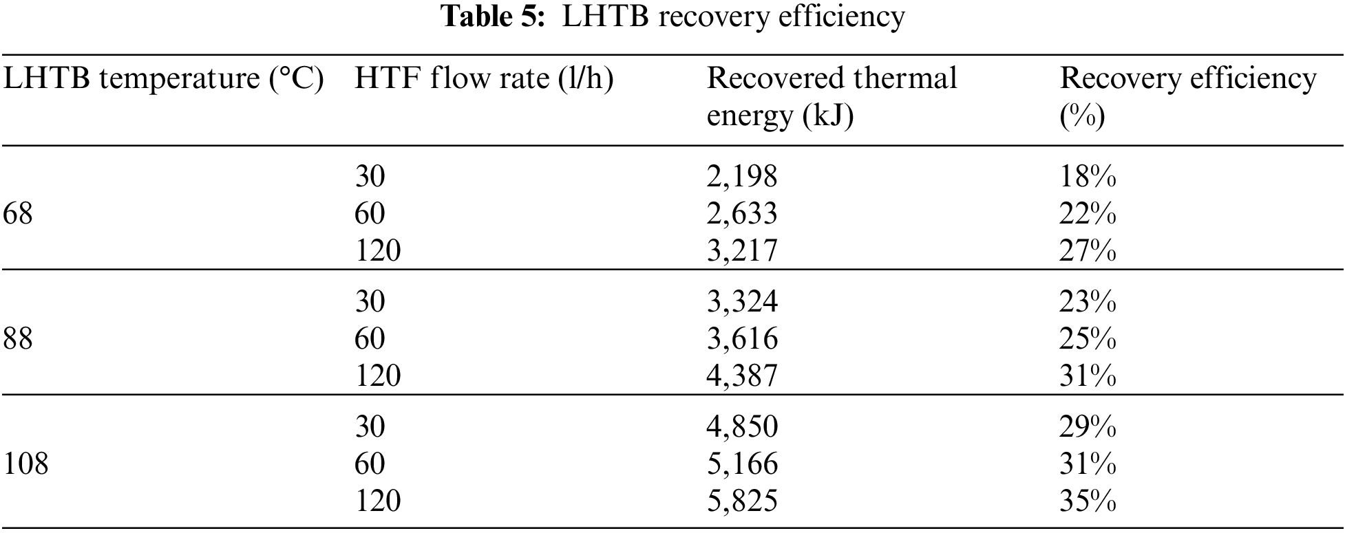
LHTB discharging efficiency is calculated based on the total amount of recovered thermal energy from the LHTB at the end of each test to the maximum extractable thermal energy at the same testing condition. Then, recovered thermal energy and recovery efficiency can be calculated using recorded data and Eq. (4). Recovered thermal energy and recovery efficiency for discharging tests are shown in Table 5. The results show that the both recovered thermal energy and recovery efficiency increase by increasing the HTF flow rate at constant LHTB temperature. For instance, LHTB at 68°C was able to deliver 2,198 kJ thermal energy at HTF flow rate of 30 l/h compare to 3,217 kJ at HTF flow rate of 120 l/h. Recovery efficiency was 18% and 27%, respectively. The highest recovery efficiency of 35% occurred in LHTB at 108°C using 120 l/h of HTF, whilst the lowest recovery efficiency of 18% occurred in LHTB at 68°C using 30 l/h of HTF. The amount of recovered thermal energy was 5,835 kJ and 2,198 kJ, respectively.
A state-of-the-art latent heat thermal battery has been developed as a potential thermal storage device to minimize the limitation of solar availability in producing hot water. The melting and solidification characteristics of PCM, the heat transfer performance, the influence of HTF temperature and flow variation and LHTB temperature are extensively studied experimentally. The system can be operated in charging and discharging modes at various operating conditions. The experimental results show that the new device performs the designed functions very well. It is worthwhile to mention that the capability of heat storage was much higher than the heat recovery. Extensive experimental investigations have been conducted to analyze the influences of the various operation parameters on the performance of the LHTB, and the results show that the HTF inlet temperature and LHTB temperature have a stronger influence on the charging and discharging process, respectively, than the HTF flow rate. Although the higher HTF flow rate has the positive effect on charging process, it has an adverse effect on discharging process. The work in this paper demonstrates the LHTB is feasible for energy storage application, however, for improving the capability of the device, there is still a good deal of work to be done. This may include the heat exchanger distribution of the fins and tubes based on the paraffin temperature profile, PCM thermal conductivity improvement, and PCM circulation inside the LHTB during the process.
Funding Statement: This research was fully founded by the University of Malaya, Faculty of Engineering, Faculty Research Grant No. GPF023A-2019.
Conflicts of Interest: The authors declare that they have no conflicts of interest to report regarding the present study.
1. Regin, A. F., Solanki, S. C., Saini, J. S. (2008). Heat transfer characteristics of thermal energy storage system using PCM capsules: A review. Renewable and Sustainable Energy Reviews, 12(9), 2438–2458. DOI 10.1016/j.rser.2007.06.009. [Google Scholar] [CrossRef]
2. Khan, M. M. A., Saidur, R., Al-Sulaiman, F. A. (2017). A review for phase change materials (PCMs) in solar absorption refrigeration systems. Renewable and Sustainable Energy Reviews, 76, 105–137. DOI 10.1016/j.rser.2017.03.070. [Google Scholar] [CrossRef]
3. Reddy, K. S., Mudgal, V., Mallick, T. K. (2018). Review of latent heat thermal energy storage for improved material stability and effective load management. Journal of Energy Storage, 15, 205–227. DOI 10.1016/j.est.2017.11.005. [Google Scholar] [CrossRef]
4. Mofijur, M., Mahlia, T. M. I., Silitonga, A. S., Ong, H. C., Silakhori, M. et al. (2019). Phase change materials (PCM) for solar energy usages and storage: An overview. Energies, 12(16), 3167. DOI 10.3390/en12163167. [Google Scholar] [CrossRef]
5. Hamad, A. J., Hussien, F. M., Faraj, J. J. (2021). Multiple phase change materials for performance enhancement of a solar dryer with double pass collector. Energy Engineering, 118(5), 1483–1497. DOI 10.32604/EE.2021.016867. [Google Scholar] [CrossRef]
6. Weiss, W., Spörk-Dür, M. (2020). Solar heat worldwide. Austria: International Energy Agency. [Google Scholar]
7. Agency, International Energy (2018). World energy outlook 2018. France: International Energy Agency. [Google Scholar]
8. Kanimozhi, B., Ramesh Bapu, B. R., Venkat, P. (2017). Thermal energy storage system operating with phase change materials for solar water heating applications: DOE modelling. Applied Thermal Engineering, 123, 614–624. DOI 10.1016/j.applthermaleng.2017.05.122. [Google Scholar] [CrossRef]
9. Iranmanesh, S., Silakhori, M., Naghavi, M. S., Ang, B. C., Ong, H. C. et al. (2021). Using graphene nanoplatelets nanofluid in a closed-loop evacuated tube solar collector—Energy and exergy analysis. Composites Science, 5(10), 277. DOI 10.3390/jcs5100277. [Google Scholar] [CrossRef]
10. Peng, Y., Zahedidastjerdi, A., Abdollahi, A., Amindoust, A., Bahrami, M. et al. (2020). Investigation of energy performance in a U-shaped evacuated solar tube collector using oxide added nanoparticles through the emitter, absorber and transmittal environments via discrete ordinates radiation method. Journal of Thermal Analysis and Calorimetry, 139(4), 2623–2631. DOI 10.1007/s10973-019-08684-w. [Google Scholar] [CrossRef]
11. Naghavi, M. S., Ong, K. S., Badruddin, I. A., Mehrali, M., Metselaar, H. S. C. (2017). Thermal performance of a compact design heat pipe solar collector with latent heat storage in charging/discharging modes. Energy, 127, 101–115. DOI 10.1016/j.energy.2017.03.097. [Google Scholar] [CrossRef]
12. Naghavi, M. S., Ong, K. S., Mehrali, M., Badruddin, I. A., Metselaar, H. S. C. (2015). A state-of-the-art review on hybrid heat pipe latent heat storage systems. Energy Conversion and Management, 105, 1178–1204. DOI 10.1016/j.enconman.2015.08.044. [Google Scholar] [CrossRef]
13. Javadi, F. S., Metselaar, H. S. C., Ganesan, P. (2020). Performance improvement of solar thermal systems integrated with phase change materials (PCMa review. Solar Energy, 206, 330–352. DOI 10.1016/j.solener.2020.05.106. [Google Scholar] [CrossRef]
14. Kalidasan, B., Pandey, A. K., Shahabuddin, S., Samykano, M., Thirugnanasambandam, M. et al. (2020). Phase change materials integrated solar thermal energy systems: Global trends and current practices in experimental approaches. Journal of Energy Storage, 27, 101118. DOI 10.1016/j.est.2019.101118. [Google Scholar] [CrossRef]
15. Esmaeilzadeh, A., Silakhori, M., Ghazali, N. N. N., Metselaar, H. S. C., Mamat, A. B. et al. (2020). Thermal performance and numerical simulation of the 1-pyrene carboxylic-acid functionalized graphene nanofluids in a sintered wick heat pipe. Energies, 13(24), 6542. DOI 10.3390/en13246542. [Google Scholar] [CrossRef]
16. Silakhori, M., Jafarian, M., Arjomandi, M., Nathan, G. J. (2017). Comparing the thermodynamic potential of alternative liquid metal oxides for the storage of solar thermal energy. Solar Energy, 157, 251–258. DOI 10.1016/j.solener.2017.08.039. [Google Scholar] [CrossRef]
17. Buckles, W. E., Klein, S. A. (1980). Analysis of solar domestic hot water heaters. Solar Energy, 25(5), 417–424. DOI 10.1016/0038-092X(80)90448-X. [Google Scholar] [CrossRef]
18. Lenel, U. R., Mudd, P. R. (1984). A review of materials for solar heating systems for domestic hot water. Solar Energy, 32(1), 109–120. DOI 10.1016/0038-092X(84)90054-9. [Google Scholar] [CrossRef]
19. Mazman, M., Cabeza, L. F., Mehling, H., Nogues, M., Evliya, H. et al. (2009). Utilization of phase change materials in solar domestic hot water systems. Renewable Energy, 34(6), 1639–1643. DOI 10.1016/j.renene.2008.10.016. [Google Scholar] [CrossRef]
20. Wu, S., Fang, G. (2011). Dynamic performances of solar heat storage system with packed bed using myristic acid as phase change material. Energy and Buildings, 43(5), 1091–1096. DOI 10.1016/j.enbuild.2010.08.029. [Google Scholar] [CrossRef]
21. Koca, A., Oztop, H. F., Koyun, T., Varol, Y. (2008). Energy and exergy analysis of a latent heat storage system with phase change material for a solar collector. Renewable Energy, 33(4), 567–574. DOI 10.1016/j.renene.2007.03.012. [Google Scholar] [CrossRef]
22. Malvi, C. S., Dixon-Hardy, D. W., Crook, R. (2011). Energy balance model of combined photovoltaic solar-thermal system incorporating phase change material. Solar Energy, 85(7), 1440–1446. DOI 10.1016/j.solener.2011.03.027. [Google Scholar] [CrossRef]
23. Varol, Y., Koca, A., Oztop, H. F., Avci, E. (2010). Forecasting of thermal energy storage performance of phase change material in a solar collector using soft computing techniques. Expert Systems with Applications, 37(4), 2724–2732. DOI 10.1016/j.eswa.2009.08.007. [Google Scholar] [CrossRef]
24. Kousksou, T., Bruel, P., Cherreau, G., Leoussoff, V., El Rhafiki, T. (2011). PCM storage for solar DHW: From an unfulfilled promise to a real benefit. Solar Energy, 85(9), 2033–2040. DOI 10.1016/j.solener.2011.05.012. [Google Scholar] [CrossRef]
25. Benli, H., Durmuş, A. (2009). Performance analysis of a latent heat storage system with phase change material for new designed solar collectors in greenhouse heating. Solar Energy, 83(12), 2109–2119. DOI 10.1016/j.solener.2009.07.005. [Google Scholar] [CrossRef]
26. Eames, P. C., Griffiths, P. W. (2006). Thermal behaviour of integrated solar collector/storage unit with 65°C phase change material. Energy Conversion and Management, 47(20), 3611–3618. DOI 10.1016/j.enconman.2006.02.029. [Google Scholar] [CrossRef]
27. Saman, W., Bruno, F., Halawa, E. (2005). Thermal performance of PCM thermal storage unit for a roof integrated solar heating system. Solar Energy, 78(2), 341–349. DOI 10.1016/j.solener.2004.08.017. [Google Scholar] [CrossRef]
28. Zeng, R., Wang, X., Xiao, W., Zhang, Y., Zhang, Q. et al. (2010). Thermal performance of phase change material energy storage floor for active solar water-heating system. Frontiers of Energy and Power Engineering in China, 4(2), 185–191. DOI 10.1007/s11708-009-0079-9. [Google Scholar] [CrossRef]
29. Naghavi, M. S., Ang, B. C., Rahmanian, B., Naghavi, S., Bazri, S. et al. (2020). On-demand dynamic performance of a thermal battery in tankless domestic solar water heating in the tropical region. Applied Thermal Engineering, 167, 114790. DOI 10.1016/j.applthermaleng.2019.114790. [Google Scholar] [CrossRef]
30. Naghavi, M. S., Ong, K. S., Badruddin, I. A., Mehrali, M., Silakhori, M. et al. (2015). Theoretical model of an evacuated tube heat pipe solar collector integrated with phase change material. Energy, 91, 911–924. DOI 10.1016/j.energy.2015.08.100. [Google Scholar] [CrossRef]
31. Badiei, Z., Eslami, M., Jafarpur, K. (2020). Performance improvements in solar flat plate collectors by integrating with phase change materials and fins: A CFD modeling. Energy, 192, 116719. DOI 10.1016/j.energy.2019.116719. [Google Scholar] [CrossRef]
32. Bilardo, M., Fraisse, G., Pailha, M., Fabrizio, E. (2020). Design and experimental analysis of an integral collector storage (ICS) prototype for DHW production. Applied Energy, 259, 114104. DOI 10.1016/j.apenergy.2019.114104. [Google Scholar] [CrossRef]
33. Mettawee, E. B. S., Assassa, G. M. (2006). Experimental study of a compact PCM solar collector. Energy, 31(14), 2958–2968. DOI 10.1016/j.energy.2005.11.019. [Google Scholar] [CrossRef]
34. Feliński, P., Sekret, R. (2017). Effect of PCM application inside an evacuated tube collector on the thermal performance of a domestic hot water system. Energy and Buildings, 152, 558–567. DOI 10.1016/j.enbuild.2017.07.065. [Google Scholar] [CrossRef]
35. Işık, S., Yıldız, C. (2020). Improving thermal energy storage efficiency of solar collector tanks by placing phase change materials in novel finned-type cells. Thermal Science and Engineering Progress, 19, 100618. DOI 10.1016/j.tsep.2020.100618. [Google Scholar] [CrossRef]
36. Kılıçkap, S., El, E., Yıldız, C. (2018). Investigation of the effect on the efficiency of phase change material placed in solar collector tank. Thermal Science and Engineering Progress, 5, 25–31. DOI 10.1016/j.tsep.2017.10.016. [Google Scholar] [CrossRef]
37. Ayompe, L. M., Duffy, A., Mc Keever, M., Conlon, M., McCormack, S. J. (2011). Comparative field performance study of flat plate and heat pipe evacuated tube collectors (ETCs) for domestic water heating systems in a temperate climate. Energy, 36(5), 3370–3378. DOI 10.1016/j.energy.2011.03.034. [Google Scholar] [CrossRef]
38. Kim, Y., Seo, T. (2007). Thermal performances comparisons of the glass evacuated tube solar collectors with shapes of absorber tube. Renewable Energy, 32(5), 772–795. DOI 10.1016/j.renene.2006.03.016. [Google Scholar] [CrossRef]
39. Zambolin, E., Del Col, D. (2010). Experimental analysis of thermal performance of flat plate and evacuated tube solar collectors in stationary standard and daily conditions. Solar Energy, 84(8), 1382–1396. DOI 10.1016/j.solener.2010.04.020. [Google Scholar] [CrossRef]
40. Ong, K. S., Tong, W. L., Sheriwati, S., Low, T. H. (2013). Performance of natural and forced convection heat pipe solar water heaters. 12th International Conference on Sustainable Energy Technologies (SET-2013), Hong Kong. [Google Scholar]
41. Algarni, S., Mellouli, S., Alqahtani, T., Almutairi, K., Anqi, A. (2020). Experimental investigation of an evacuated tube solar collector incorporating nano-enhanced PCM as a thermal booster. Applied Thermal Engineering, 180, 115831. DOI 10.1016/j.applthermaleng.2020.115831. [Google Scholar] [CrossRef]
42. Moffat, R. J. (1988). Describing the uncertainties in experimental results. Experimental Thermal and Fluid Science, 1(1), 3–17. DOI 10.1016/0894-1777(88)90043-X. [Google Scholar] [CrossRef]
 | This work is licensed under a Creative Commons Attribution 4.0 International License, which permits unrestricted use, distribution, and reproduction in any medium, provided the original work is properly cited. |