| Energy Engineering |
DOI: 10.32604/ee.2022.017718
ARTICLE
A Design of 220 kV Line Protection Action Deduction System Based on Numerical Simulation
1State Grid Hebei Electrical Power Company Research Institute, Shijiazhuang, 050021, China
2State Grid Hebei Electrical Power Company, Shijiazhuang, 050021, China
3Wuhan Kemov Electric Co., Ltd., Wuhan, 430223, China
*Corresponding Author: Daming Zhou. Email: m201971533@hust.edu.cn
Received: 01 June 2021; Accepted: 25 August 2021
Abstract: Accurate conditions monitoring and early wrong action warnings of relay protection in the Smart Substation is the basic guarantee to realize the normal operation of primary and secondary system of the power grid. At present, the traditional operation and maintenance monitoring methods of relay protections have poor timeliness, while some automatic monitoring methods have insufficient early warning performance, and lack the online action deduction function independent of the actual device. In this paper, a design method of integrated action deduction system including protection logic reasoning and software and hardware operation condition is proposed. The system can receive real-time operation information of protection online, simulate different types of faults, and output the recording information of sub modules belongs to the action deduction system. It can realize the online monitoring of device faults such as deducing the correctness of setting values at a certain time in the future, giving the wrong action warnings and predicting the probability of them as well, which effectively improves the operation and maintenance efficiency of the secondary system in the intelligent substation.
Keywords: Intelligent substation; numerical simulation; relay protection; conditions monitoring; wrong action warning
With the rapid development of the third industrial revolution centered on information technology, the intelligence of line relay protection devices is constantly improving and its operating data presents the characteristics of massive, high-speed updating and multi-source heterogeneous [1–5]. It proposes a difficult problem for realizing comprehensive perception of relay device conditions and faults early warning. The traditional operation and maintenance monitoring method has heavy workloads and poor timeliness in dynamic operating environment, resulting in occasional power grid blackout accidents caused by untimely protection conditions monitoring [6–8].
At present, many scholars have carried out relevant researches on the online monitoring, Simulation design and action deduction of relay protection conditions. Liu et al. construct the correlation matrix of relay protection conditions information based on the physical and logical connection of the secondary system, and then uses the matrix to monitor the conditions of relay protection [9]. However, the model relies too much on SV/GOOSE data, and the monitoring of the action logic is not intuitive enough. In literature [10], the D5000 platform is used to construct the automatic inspection system of protection device, which effectively integrates the functions of online monitoring, professional inspection, information sharing and releasing, etc. Li et al. design a simulation test system based on local protection [11]. The simulation test system automatically loads test cases to realize automatic verification of protection function logic of the protection device. However, the platform lacks the function predicting the future action. In literature [12], a closed-loop simulation platform of relay protection based on the adaptive THD reconstruction of output signal is designed. Yu et al. constructed a set of protection simulation system based on MATLAB and digital to analog conversion module combined with wavelet de-noising [13]. And Huang et al. established a dynamic simulation platform of the action logic of the integrated remote standby intelligent protection center based on the sequential Petri net [14]. However, in the above platforms, the protection logic modeling is too simple, which cannot match the logic design of the real device. Some of them directly relies on the real device for operation. In addition, these platforms cannot analyze the message data of the monitoring substation based on the communication protocol, and they are more used for teaching demonstration, which cannot realize the online action deduction independent of the real device. In literature [15], the action of line distance protection is predicted by adding fault disturbance excitation. Xu et al. proposed the fuzzy prediction method of the line protection action condition in the intelligent substation. based on information trend prediction and combination weighting [16]. Li et al. use continuous time Markov chain to predict relay protection action [17]. However, the above methods cannot predict the probability of device malfunction for a longtime span, and fail to consider the dynamic impact of planned maintenance on device malfunction on the time axis.
The numerical simulation technology can realize the real-time mapping of device conditions by establishing the equivalent simulation model of it, and constructing the information interaction system which keeps the model being synchronized with the real device and simulates in parallel. It is very important to establish the numerical simulation system of line relay protection to improve the visibility of relay operation conditions and the analysis ability of device failure mechanism.
This paper applies the numerical simulation technology to the conditions monitoring and action deduction of 220 kV line relay protection device. According to the relevant message specification of protection communication in IEC61850 standard, a 220 kV line protection conditions monitoring and action deduction system is developed based on the NARI PCS-931A. By mapping the main action logic, including distance protection, longitudinal differential protection, zero-sequence over-current protection, tripping and reclosing subsystems, and the software and hardware operation conditions data of the device, the real-time receiving of the relay protection conditions information can be achieved. And the simulation of different types of faults can predict the correctness of setting values at a specific time in the future and give the wrong action warnings as well, and the dynamic Markov chain could provide the probability of protection device wrong actions including operation rejection or mal-operation in the future.
Based on the numerical simulation, this paper proposes an action deduction system which can comprehensively consider the protection logic function and the conditions of software and hardware. The method can not only receive and monitor the condition data of device in real time, but also deduce the possible future action independent of the device itself by simulating the power grid faults, so as to check whether the setting values are correct and give early warnings to the possible malfunctions. In addition, due to the weak regularity of the condition data of the hardware and software, the above information in an action deduction task can be regarded as stable in a short time in the future, and the action deduction task with longer time span far from now should not use the above information. This paper firstly considers the influence of aging and maintenance on the probability of wrong action, and the prediction of wrong action probability in the far future is realized based on the dynamic modified Markov chain. The goal of the action deduction can be achieved by simulating the occurrence of power grid failure based on the real-time setting values of the device.
2 Structural Design of 220 kV Line Protection Action Deduction System
The structural system of the relay protection simulation system should effectively support the data transmission of physical device, the conditions tracking of the virtual system to the device and the necessary conditions information interaction. Besides, it should realize the deduction of relay protection actions based on the dynamic evolution of the external environment. Therefore, the line protection simulation system designed in this article includes four parts: the operating environment subsystem, the protection logic function subsystem layer, the device software and hardware conditions subsystem, and the data analysis front end, as shown in Fig. 1. In this article, the operating environment subsystem will be built through the Simulink/Powerlib distributed parameter module based on the actual operating environment. This article will design a 220 kV double-circuit system as the external environment and it will be introduced in the chapter of case analysis. The data analysis front-end is an interactive interface for intuitively understanding protection conditions information. The following content will focus on the protection logic function subsystems and the device software and hardware conditions subsystems.
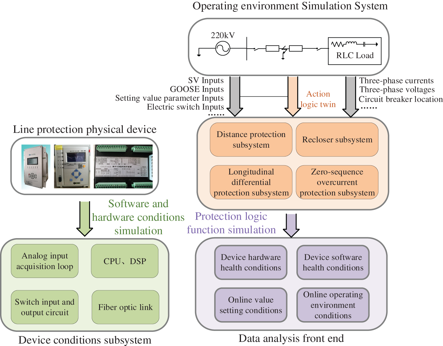
Figure 1: Structure of 220 kV line protection action deduction system
3 Design of 220 kV Line Protection Logic Function Subsystem
The 220 kV line protection logic function subsystem includes the distance protection subsystem, the longitudinal differential protection subsystem, the zero-sequence overcurrent protection subsystem, the reclosing subsystem, and the startup, oscillation blocking, trip logic subsystems. This subsystem can effectively realize the tracking and monitoring of conditions data such as setting values, control words, protection online monitoring information and so on. It can also simulate the faults such as metallic faults inside and outside the protection zone, short-circuit faults through transition resistance and the open phase faults, so as to realize the deduction of the relay protection device's action. The logic function subsystem is built in the Simulink CONTINUOUS simulation environment. And it will complete the operation logic by receiving the protection setting values, control words, strap setting values and the GOOSE input interface information transmitted by the physical device in real time.
3.1 Design of Distance Protection Subsystem
The distance protection subsystem is composed of power frequency variation, low voltage, phase-to ground and phase-to-phase distance protection sub-modules. The power frequency variation distance protection sub-module judges the fault type by analyzing the fault component of the line voltage when the short circuit occurs [18]. The action conditions are as follows:
For the phase-to-phase fault:
For the phase-to-ground fault:
where
Phase-to ground and phase-to-phase distance protection sub-modules has 3 sections. All of them use the positive sequence voltage as the polarized voltage, and the phase comparison method is used to determine the fault type. The low-voltage distance protection sub-module is similar to the phase-to ground and phase-to-phase distance protection. When the positive sequence voltage is less than 10% of the rated phase voltage, it determines whether a three-phase short-circuit fault occurs at the outlet of the protective circuit breaker. The action conditions of the phase-to-ground and phase-to-phase protection are as follows.
For phase-to-ground protection, the working voltage is:
The polarized voltage is:
For phase-to-phase protection, the working voltage is:
The polarized voltage is:
The above module action criterion is:
where
3.2 Design of Longitudinal Differential Protection Subsystem
Longitudinal differential protection subsystem includes the phase current and zero-sequence current differential protection modules for each phase. The phase current differential protection module is composed of the power frequency variation differential protection module and the steady conditions differential protection modules including Sections I and II. When one of them meets the action condition, after a certain delay to avoid error caused by data fluctuation, the longitudinal differential protection of a single phase will act. The action conditions of differential protection are as follows:
The steady-conditions phase protection action conditions are as follows:
3.3 Design of Zero-Sequence Overcurrent Protection Subsystem
The zero-sequence overcurrent protection subsystem includes zero-sequence power direction identification module, Sections I, II, and III zero-sequence current protection modules and this subsystem can be combined with the reclosing module to achieve accelerated action [19].
The action condition of zero-sequence power direction identification module is:
where
For the Section I zero-sequence current protection, the starting current is:
where
For Section II zero-sequence current protection, the starting current is:
where
For Section III zero-sequence current protection, the starting current is:
where
3.4 Design of the Reclosing Subsystem
The reclosing subsystem adopts one-time reclosing design, which can realize single-phase, three-phase and comprehensive reclosing functions, and three-phase reclosing includes detecting line voltage disappearance to reclose, detecting synchronicity to reclose and direct reclosing.
The protection startup modules of this system include four modules: current change startup, zero-sequence overcurrent startup, position non-corresponding startup, and low voltage or long-jump startup. The PT and CT disconnection judgment logic modules respectively calculate the sum of the phase voltage phasor, the positive-sequence phase voltage and the zero-sequence current amplitude at the measuring point. The phase selection module of this system is designed based on the current differential phase selection method, the working voltage variation phase selection method and phase comparison method between zero-sequence and positive-sequence current. The completed design module is connected based on the trip logic. The trip outlet will correspond to the GOOSE output optical port on the back panel of the physical device, thereby simulating the output signal when the protection device is put into operation. The logic function simulation of the protection device can be realized through the above modules. The design of protection logic function subsystem based on Simulink are shown in the Appendix A. Figs. A1–A5each represents the logic design of distance protection subsystem, longitudinal differential protection subsystem, zero-sequence overcurrent protection subsystem, reclosing subsystem, and the whole protection tripping movement.
3.5 Design of the Phase Selection Subsystem
The phase selection subsystem includes three phase selection modules: current differential phase selection, phase selection by working voltage variation, phase selection by phase comparison of
For current differential phase selection, when the power frequency variation relay and the steady-conditions differential relay act, the action phase is selected as the fault phase. For phase selection by working voltage variation, the protection has six phase selection measuring elements to measure the
For the phase selection by phase comparison of
Select Section A when the following formula is satisfied:
Select Section B when the following formula is satisfied:
Select Section C when the following formula is satisfied:
After the section being determined, the magnitude of three phase current are compared to judge the fault type. If this phase, whose name is as same as the section name, has larger current magnitude than others, then the fault type is the single-phase grounding fault of this phase, otherwise the other two phases short circuit fault. For example, if the ratio meets condition of choosing Section A, then the three phase current magnitudes will be compared. Once the magnitude of phase A current is larger than phases B and C current magnitudes, the fault type is phase A grounding fault, otherwise the phase B to phase C short circuit fault.
4 Design of the Device Conditions Subsystem Layer
At present, the commonly used microcomputer relay protection device includes AC converter module for receiving three-phase electrical signals of the system, power supply module for relay power supply, low-pass filter module for filtering high-frequency noise signals, analog-to-digital converter module, core module for protection logic operation composed of CPU and DSP, communication module for connecting intelligent terminal, hardware and software The GOOSE module to receive the required input of protection operation and output relay action signal is shown in Fig. 2. In the PCS-931A, the input is transmitted through the 24 V optocoupler module. Considering the extended application of the system to the “six-unification” and “nine-unification” type line protectionin the intelligent substation, the input is designed to read from GOOSE message and compatible with the optocoupler module input. One of the two input methods can be selected as the input method. The operation conditions of various modules especially the core modules, will affect the input values, calculation and output of the protection; In addition, if the software of relay protection device, such as the configuration files of GOOSE, SV, setting values and switching value input and output, are abnormal, it will cause the deviation of logic operation and relay action. This paper designs the device state simulation subsystem layer to map the above protection device conditions. The abnormal operation condition of device software and hardware will disturb or block the value of specific logic circuit or module, sending out alarming signal. The simulation system obtains condition data mentioned above by parsing SCD file, carries out real-time monitoring and displays them at the data analysis front end. The data closely related to logic operation, such as SV message of three-phase electrical signals, and GOOSE message of control words setting values, will be transmitted to the logic function simulation system for calculation. The data analysis front end will analyze the COMTRADE recording file of the device action under the simulated fault environment. If the fault cannot be removed accurately, the mis-operation alarm will be given. The operation and maintenance personnel can analyze the cause of the fault by combining the alarm message transmitted by the SCD file and the setting results of the protection setting values and the control words. The design of device conditions data analysis is shown in Fig. 3.
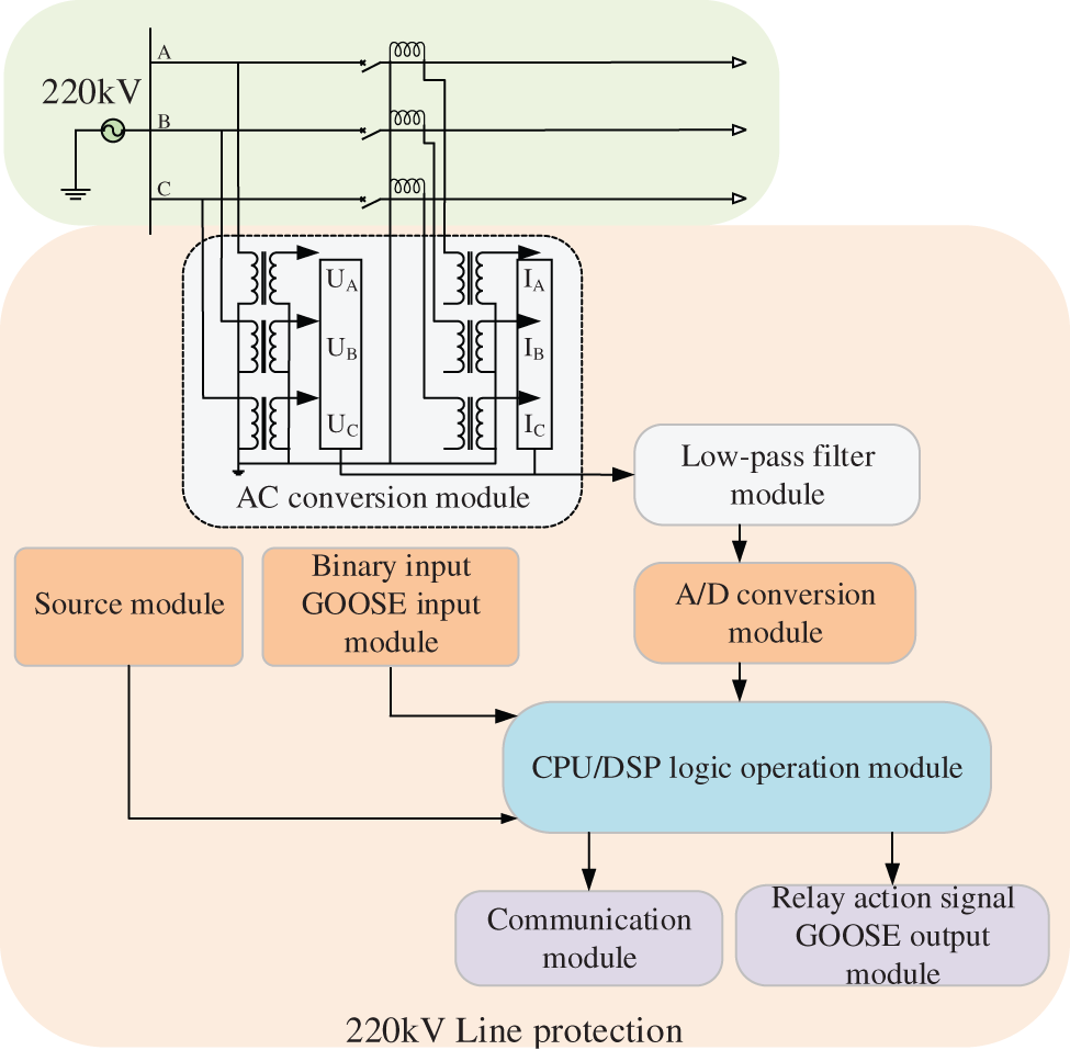
Figure 2: Structure of 220 kV line protection hardware subsystem
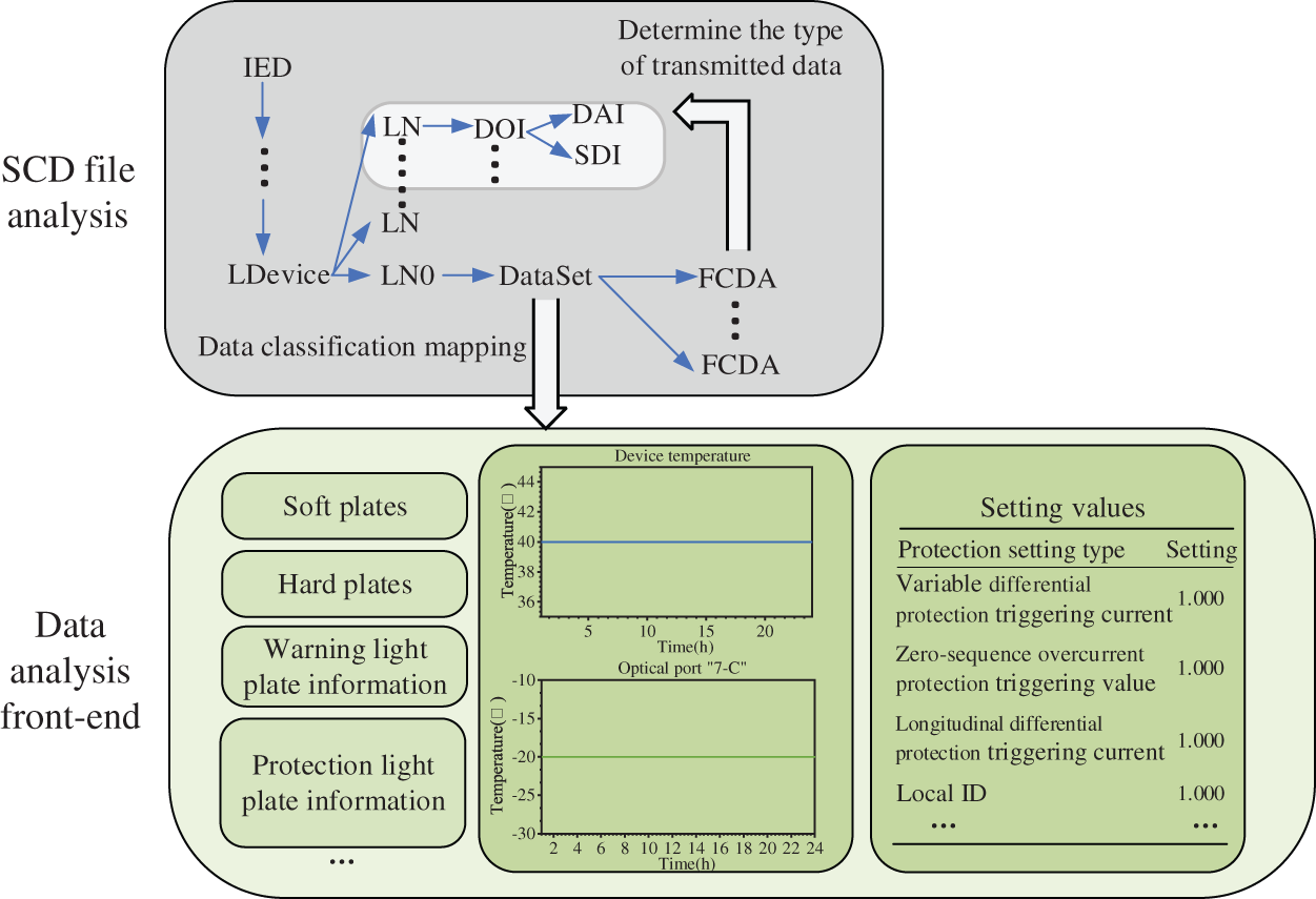
Figure 3: 220 kV line protection software and hardware conditions data transmission channel design
It can be seen that the device conditions subsystem can monitor the operation parameters of software and hardware in real time, and lock the relevant logic function subsystems according to the fault message. For example, the warning message, SV channel delay exceeding the limitation, will lock the longitudinal differential protection subsystem. When the action prediction of the near future is made, the device software and hardware conditions can be regarded as stable, However, with the extension of time, the software and hardware conditions data should not be kept stable when the protection action is simulated and predicted in the far future, and the operation rejection or mal-operation caused by the software and hardware faults should not be identified, This paper also proposes a relay protection overall condition prediction model based on Weibull distribution dynamic optimization Markov chain, which preliminarily deduces the probability of future device operation rejection and mal-operation.
When the line relay protection is in normal operation, affected by the line fault, the device will be transferred between the action condition and the non-action condition. With the increase of service years, the device will appear the condition of reflecting to operate, mis-operation and fault self-checking due to the failure of the software and hardware. At the same time, the planned maintenance will update the condition of the device, and reduce the probability of wrong actions to a certain extent. Line protection can be divided into thirteen categories according to action, maintenance, operation rejection, maloperation and whether the faults can be self-checked [17]. In this paper, the maintenance is further divided into emergency maintenance and planned maintenance.When the planned maintenance meets the maintenance cycle, the protection condition will be reset, and the time-varying correction factor is introduced to optimize the rejection or maloperation rate after maintenance. The overall structure is shown in Fig. 4.
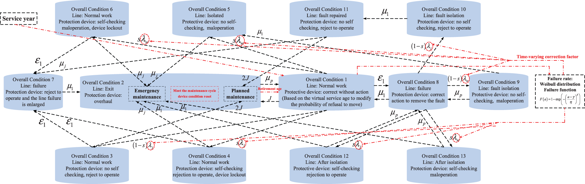
Figure 4: Space diagram of 220 kV line protection action state
The condition transition process of relay protection conforms to the continuous time Markov chain [17]. The matrix composed of transition probabilities between conditions is denoted as:
Markov chain defines the transition rate matrix Q and G(t) [20] as follows, this paper modifies the original G(t) and considers the influence of maintenance. In Eq. (21), t is the service year and the unit is hour, the k is the number of planned maintenances, and the q is the parameter representing the maintenance quality which is decided by experience.
Since the matrix P and Q fulfill the backward equation of Kolmogorov, the transition probability matrix can be solved as shown in Eq. (22). In this paper, combined with Weibull failure rate distribution function, the failure rate G(t) is introduced into Q, so as to achieve the purpose of dynamic optimization of condition transition probability.
According to the device condition monitoring and maintenance business, this paper divides the key nodes on the operation life of relay protection device into maintenance points and monitoring points (including maintenance points). The maintenance cycle is T, and there are n monitoring points between maintenance points
Since the line protection will return to normal condition after maintenance and operation, the probability of condition 1 after the device passes through the k-th maintenance point, and the probability of each condition Condition(time is tk) = [1, 0,..., 0]1×13. The condition probability vector of each point between the k and k+1 maintenance points is shown in Eqs. (24) and (25), that is, each monitoring point will update the initial condition probability vector. The condition probability of tk,i,j at a certain time between i and i+1 is calculated with the condition probability of its nearest monitoring point i as the initial value. The final condition of the device will be predicted based on the maximum value of probability, and the condition monitoring value of each monitoring point will be used to represent the device condition in the monitoring period.
5 Data Interaction Design of 220 kV Line Protection Action Deduction System
The application of 220 kV line protection action deduction system needs power grid parameters and line protection parameters. Power grid parameters will participate in the construction of Operating environment subsystem. Generally, the external system of the line protection has strict operation requirements and stays unchanged in usual. Therefore, the power grid parameters are static data and being input before operation; the line protection parameters are obtained by the secondary on-line monitoring system (intelligent recorders) of the substation through communication with the actual protection device based on the DLT860/IEC61850 protocol. The obtained parameters are actively delivered to the action deduction system in the form of packaged data files. The action deduction system is deployed in the secondary on-line monitoring master station. The communication with the master station of the secondary online monitoring system is established through TCP connection, and the data delivered by the other party is obtained regularly, and the data parameters of relay protection device are transmitted in real time to complete the expected application function. The data interaction process is shown in Fig. 5.
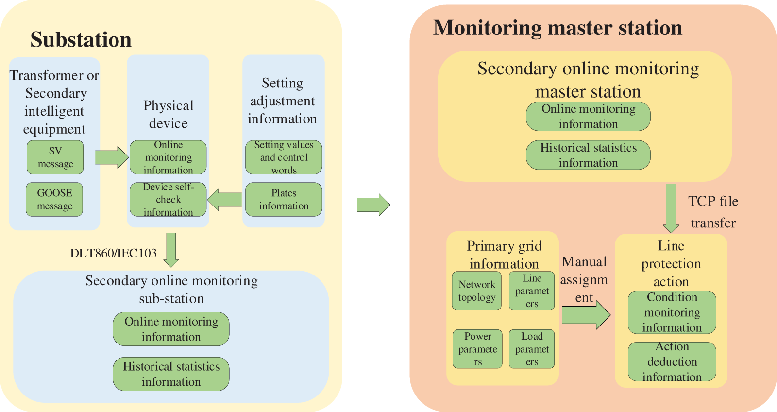
Figure 5: Structure of 220 kV line protection hardware subsystem
6.1 Brief Introduction of Calculation Case Data and Calculation Parameters
In order to verify that the line protection simulation system proposed in this paper has good condition monitoring and action deduction effects, this paper constructs a 220 kV double circuit line model with distributed parameters as shown in Fig. 6. The line impedance parameters comes from literature [21]. The total length of a single circuit is 300 km. The line protection receives the power frequency amplitude and phase angle values obtained from the current and voltage measuring components installed at the beginning and end of the line. The protection is installed at the beginning of the line and controls the opening and closing of head-end circuit breaker. Distance protection and zero-sequence overcurrent protection are judged based on the measured value of the head-end electrical signals, and the differential protection is combined with the double-end electrical signals to judge. The protection zone is 150 km. Subsequently, this paper designs four typical types of faults: metallic faults within and outside the protection zone, short-circuit through transition resistance, and open phase operation faults, and several different fault places, which together used to verify the excellent performance of the system in tracking device conditions and realizing action prediction. The reclosers use the comprehensive recloser method. The single-phase reclosing time is 100 ms, and the three-phase reclosing time is 150 ms. The simulation step is 0.1 ms.
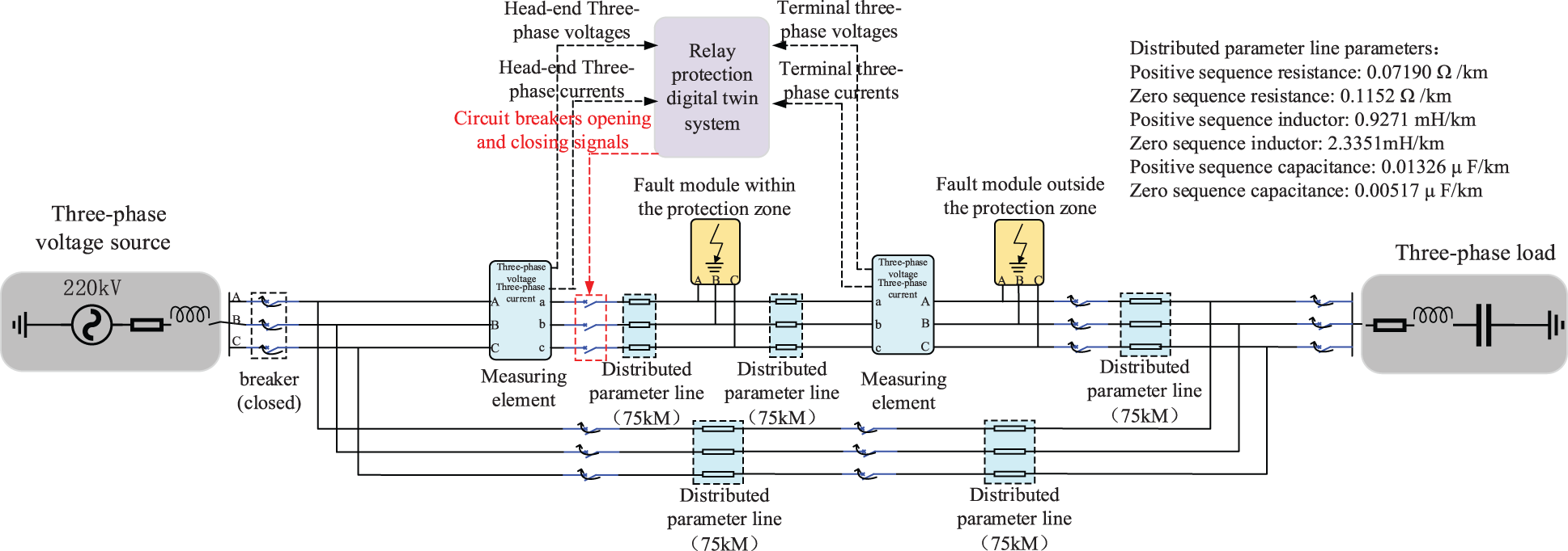
Figure 6: Structure of 220 kV double-circuit system
6.2 Grounding and Interphase Faults within the Protection Zone
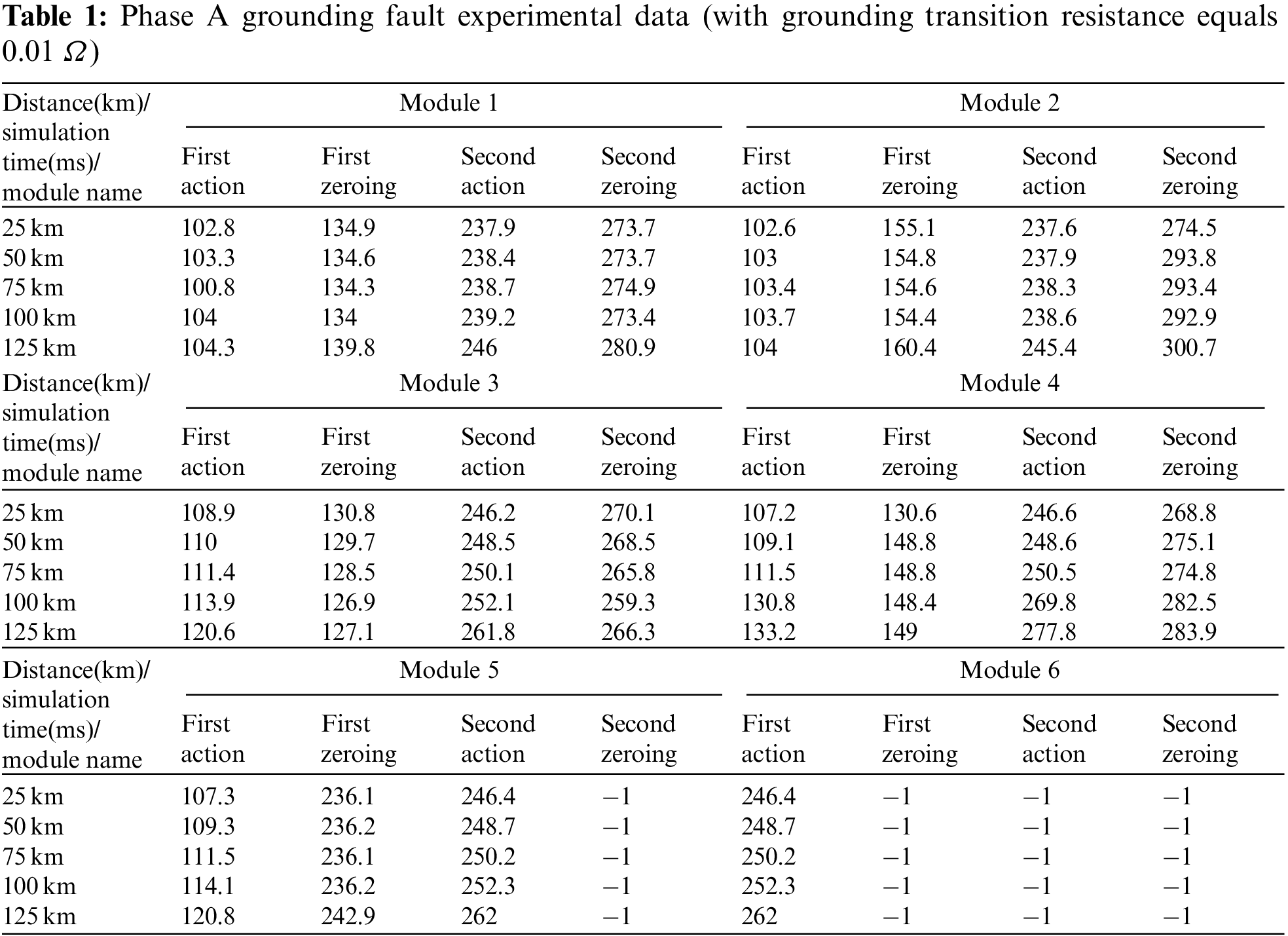
This section designs three types of faults within the protection zone: single phase A grounding fault, two (B, C) phases short circuit fault and two (A, C) phases grounding fault. The occurrence time of each fault is the 100 ms of the simulation time, the duration is 200 ms, and the total simulation time is 400 ms. The fault occurs at the 25, 50, 75, 100 and 125 km away from the head of the line. The experimental grounding resistance values include 0.01 Ω (metallic grounding), 10 Ω and 30 Ω. The operable modules in the simulation system include grounding distance protection I module (the impedance setting value is set according to the goal protecting the 85% range of the full line section) and II (the impedance setting value is set according to the goal protecting the 85% range of the range protected by the next protection zone grounding distance protection I), and the power frequency variation distance protection module (the impedance setting values is set according to the goal protecting the 85% range of the full line section) from the distance protection subsystem, and the longitudinal differential protection subsystems.
Taking the phase a metallic grounding at 75 km of the line as an example, the input protection is distance protection I and power frequency variation distance protection, Firstly, the zero-sequence/negative sequence current ratio phase selection module calculates that the ratio, I0/I2A, is between ± 60° when the fault happens, so the phase selector determines that the fault occurs in Section A, at the same time, by comparing the amplitude of three-phase positive sequence current, the element determines that phase A grounding fault occurs in the line rather than BC two-phase grounding fault, as shown in Fig. 7a, so the zero-sequence/negative sequence current ratio phase selection module sends phase A grounding fault signal for the first time at 100.8 ms; At the same time, the phase selection of power frequency variation distance protection module calculates that the power frequency variation of phase A voltage is higher than twice the power frequency variation of BC phase voltage at 103.4 ms, sending phase A grounding fault signal, as shown in Fig. 7b. So far, the line protection has successfully selected the fault phase.
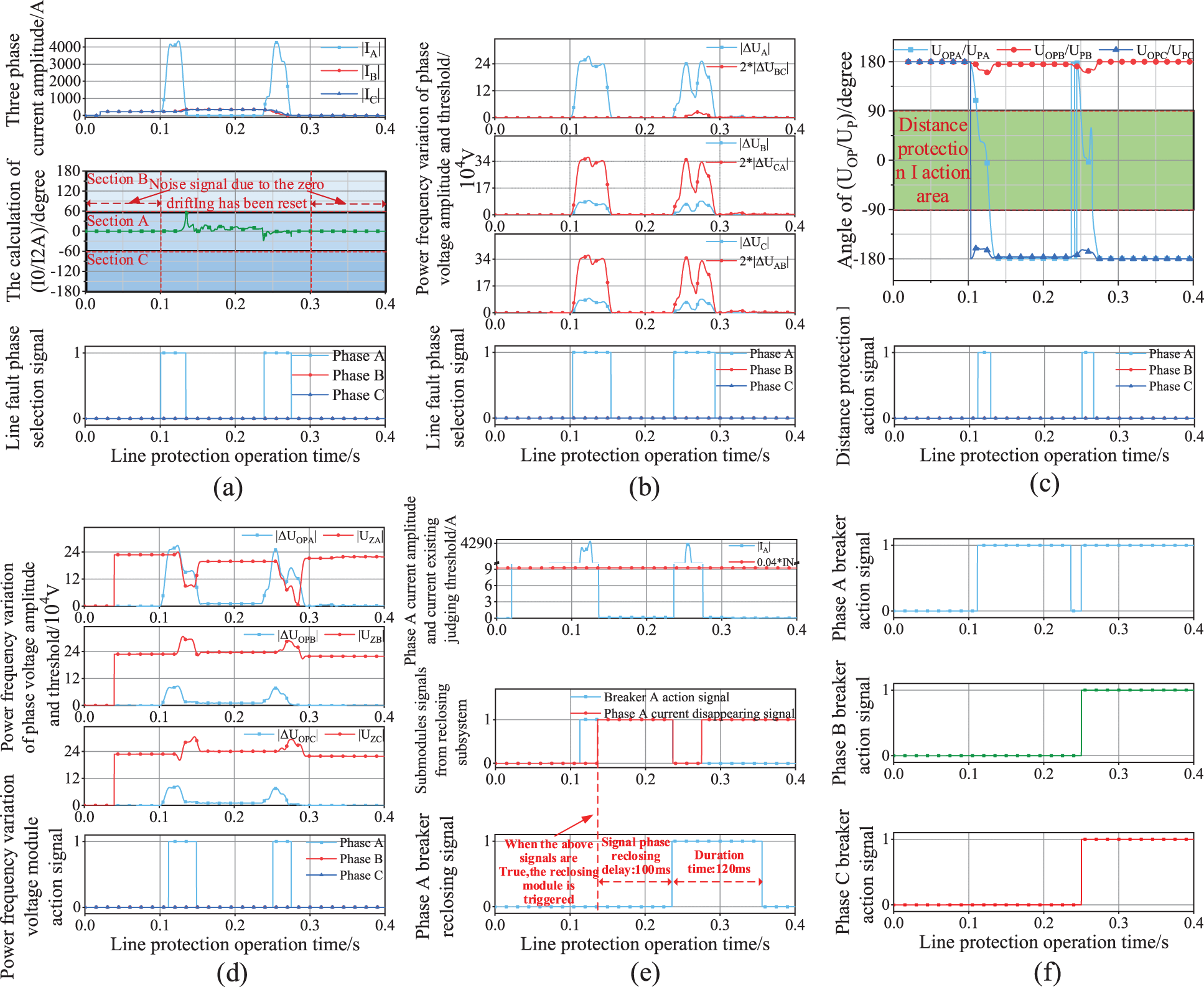
Figure 7: Simulation system action signal diagrams of phase A grounding fault within the protection zone
Note: (a) Zero-sequence/negative sequence current ratio (I0/I2A) phase selection module recording signals; (b) Phase selection of power frequency voltage variation module; (c) Grounding distance protection I module recording signals; (d) Power frequency variation distance protection module recording signals; (e) Reclosing subsystem recording signals; (f) Three-phase breakers actions recording signals.
After the fault occurs, the grounding distance protection I module determines that the UOPA/UPA ratio meets the action conditions in 111.4 ms, as shown in Fig. 7c, and the power frequency variation distance protection module determines ΔUOPA is greater than the action threshold in 111.5 ms. As shown in Fig. 7d, both send out the protection allowable action signal, and the latter also sends out the phase selection signal. Combined with the above other phase selection signals, the phase A breaker acts at 111.5 ms. The zero-sequence/negative sequence current ratio phase selection module, phase selection of power frequency voltage variation module, grounding distance protection I module and power frequency variation distance protection module return to 0 in 134.3, 154.6, 128.5 and 148.8 ms, respectively, as shown in Figs. 7a–7d.
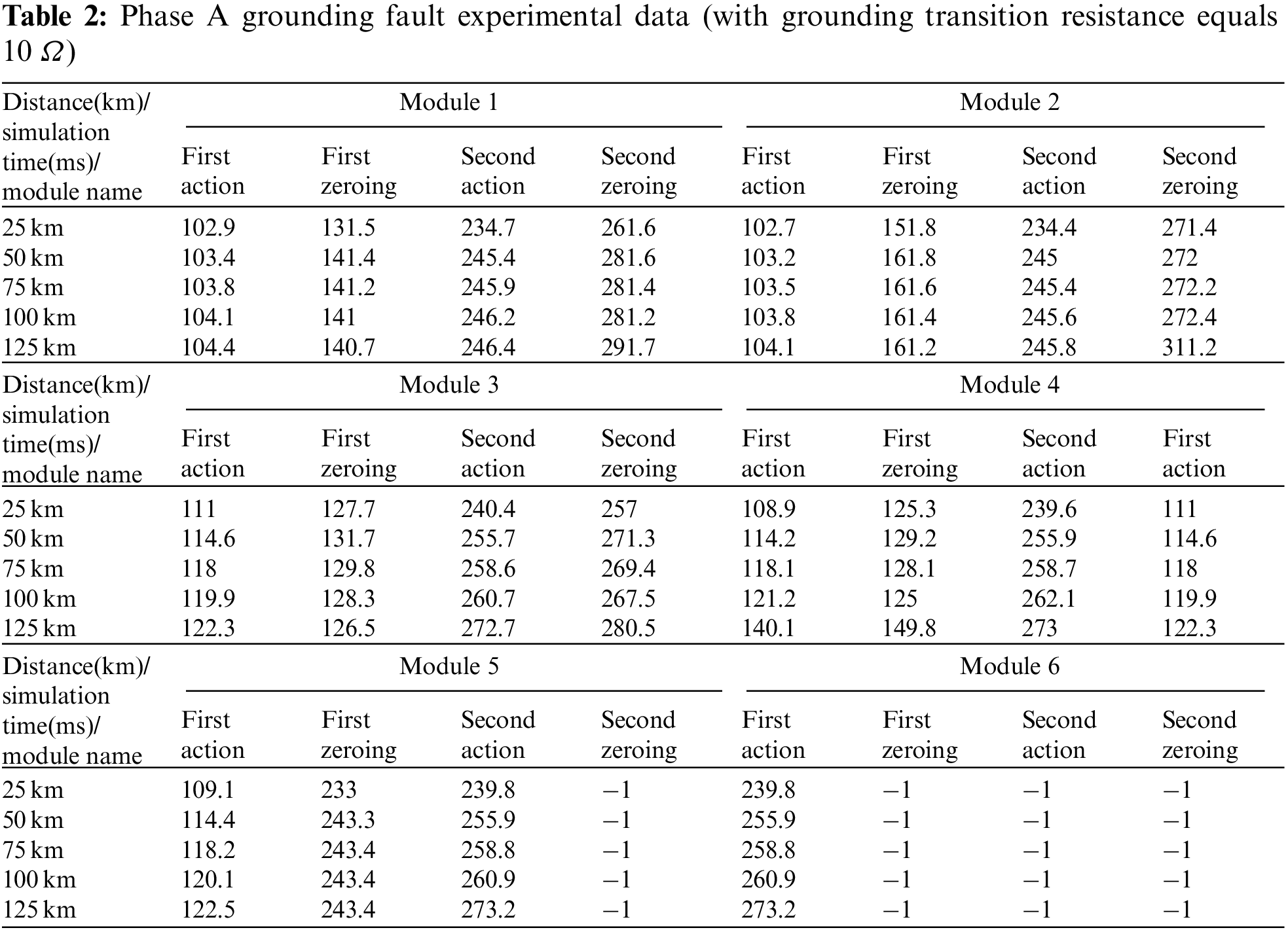
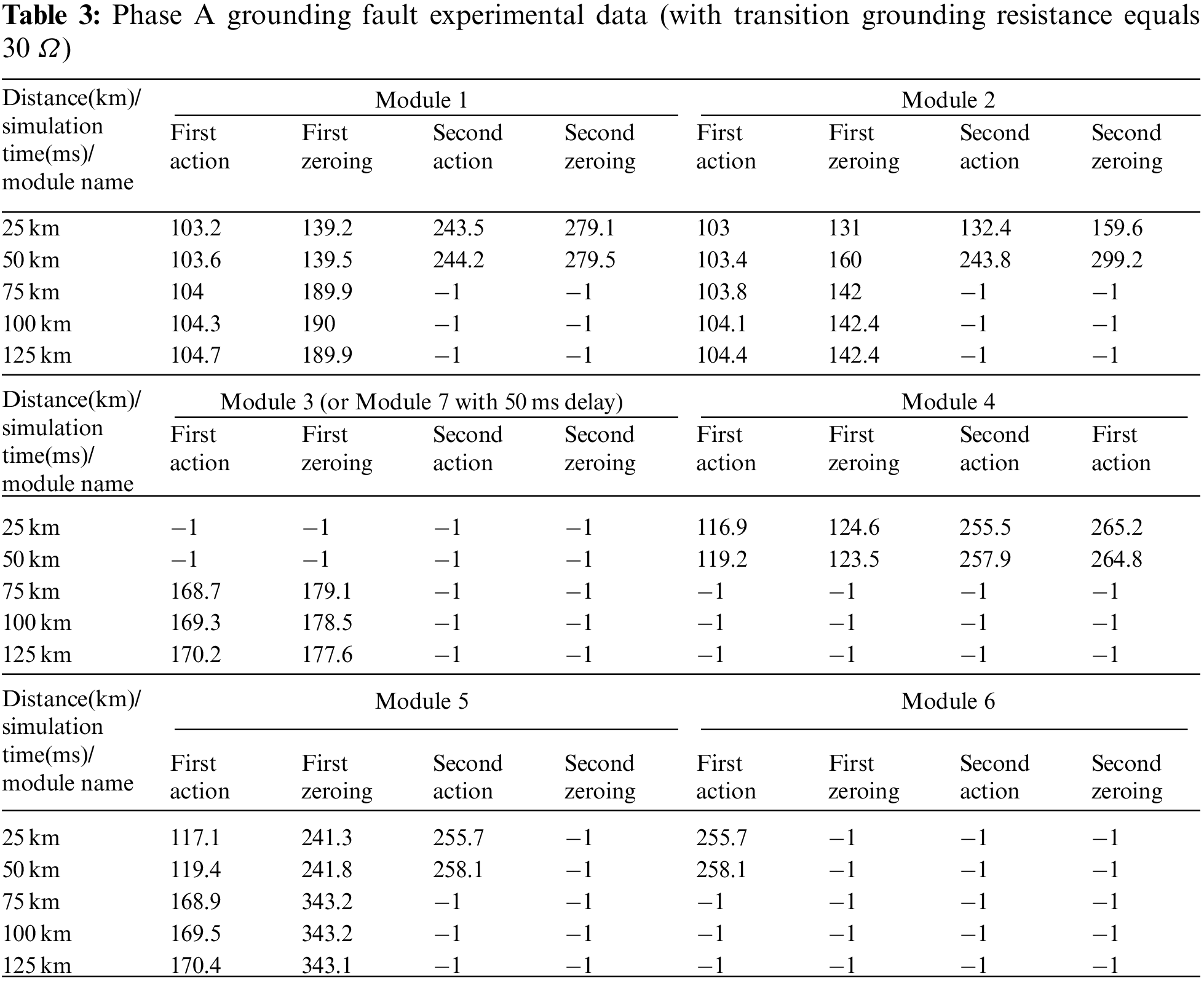
Protection single-phase reclosing needs to wait for 100 ms before closing after phase A sends out tripping signal and phase A current disappearing signal (IA < 0.04 * IN, IN is the current rating). The latter signal is sent out at 136.1 ms, slightly lagging behind the former, so the protection is reclosed at 236.1 ms. as shown in Fig. 7e, the fault still exists at this time. The zero-sequence/negative sequence current ratio (I0/I2A) phase selection module, phase selection of power frequency voltage variation module, grounding distance protection I module and power frequency variation distance protection module resend “1” signals respectively in 238.7, 238.3, 250.1 and 250.5 ms. Due to the comprehensive reclosing mode, the three phases breakers act in 250.2 ms and does not reclose again. The three-phase breakers action signals are shown in Fig. 7f. The above four modules respectively return to 0 again in 274.9, 293.4, 265.8 and 274.8 ms, as shown in Figs. 7a–7d. The faults happen at different places with different attributes yet using distance protection subsystem to judge are also listed in Tables 1–3. Modules 1–6 respectively represent the zero-sequence/negative sequence current ratio (I0/I2A) phase selection module; the phase selection of power frequency voltage variation module; the grounding distance protection I module; the power frequency variation distance protection module; phase A breaker; phases B, C breakers and the grounding distance protection Ⅱ module. The “−1” means the module does not act. It can be seen that when the fault occurs without grounding transition resistance, all the modules function well. However, when the transition resistance is larger than 30 Ω, the grounding distance protection I module fails to function due to the measurement impedance falling outside the impedance circle according to the mho characteristic, and with the fault distance enlarging, the power frequency variation distance protection module fails to function too, and the grounding distance protection Ⅱ module start to act, which causes action delay. By the time the breakers reclose, the fault has already disappeared and all the modules will not act again.
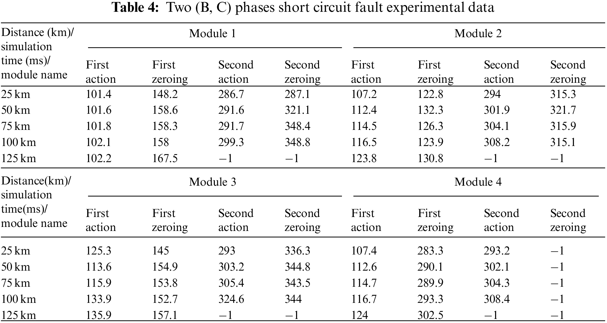
If the two (B, C) phases short circuit fault occurs, the zero-sequence/negative sequence current ratio phase selection module is useless due to the lack of zero sequence current; the phase selection of power frequency variation distance protection module calculates that the power frequency variation of phase B to phase C voltage is higher than other interphase voltages at 101.8 ms, sending phase B and phase C fault signal, as shown in Fig. 8a. So far, the line protection has successfully selected the fault phases. After the fault occurs, the phase-to-phase distance protection I module determines that the UOPBC/UPBC ratio meets the action conditions in 114.5 ms, as shown in Fig. 8b, and the power frequency variation distance protection module determines ΔUOPBC is greater than the action threshold in 115.9 ms. As shown in Fig. 8c, both send out the protection allowable action signal, and the latter also sends out the phase selection signal. Combined with the above other phase selection signals, three phases breakers act at 114.7 ms. It can be seen that although there is an error in the power frequency variation distance protection module and the module returns to 0 for a short time. Since the line has tripped successfully, there will be no mis-operation. The phase selection of power frequency voltage variation module, phase to phase distance protection I module and power frequency variation distance protection module return to 0 in 158.3, 126.3 and 153.8 ms, respectively, as shown in Figs. 7a–7c. Protection three phases reclosing needs to wait for 150 ms before closing after three phases send out tripping signal and three phases current disappearing signal. The latter signal is sent out at 139.9 ms, so the protection is reclosed at 289.9 ms. as shown in Fig. 7d, the fault still exists at this time. The phase selection of power frequency voltage variation module, phase to phase distance protection I module and power frequency variation distance protection module resend “1” signals respectively in 291.7, 304.1 and 305.4 ms. Due to the comprehensive reclosing mode, the three phases breakers act in 304.3 ms and does not reclose again. The three-phase tripping signals are shown in Fig. 7e. The above three modules respectively return to 0 again in 348.4 ms, 315.9 and 343.5 ms, as shown in Figs. 7a–7c. The faults happen at different places with different attributes yet using distance protection subsystem to judge are also listed in Table 4, The “−1” means the module does not act. Modules 1–4 respectively represents the phase selection of power frequency voltage variation module; the phase-to-phase distance protection I module; the power frequency variation distance protection module and three phases breakers.
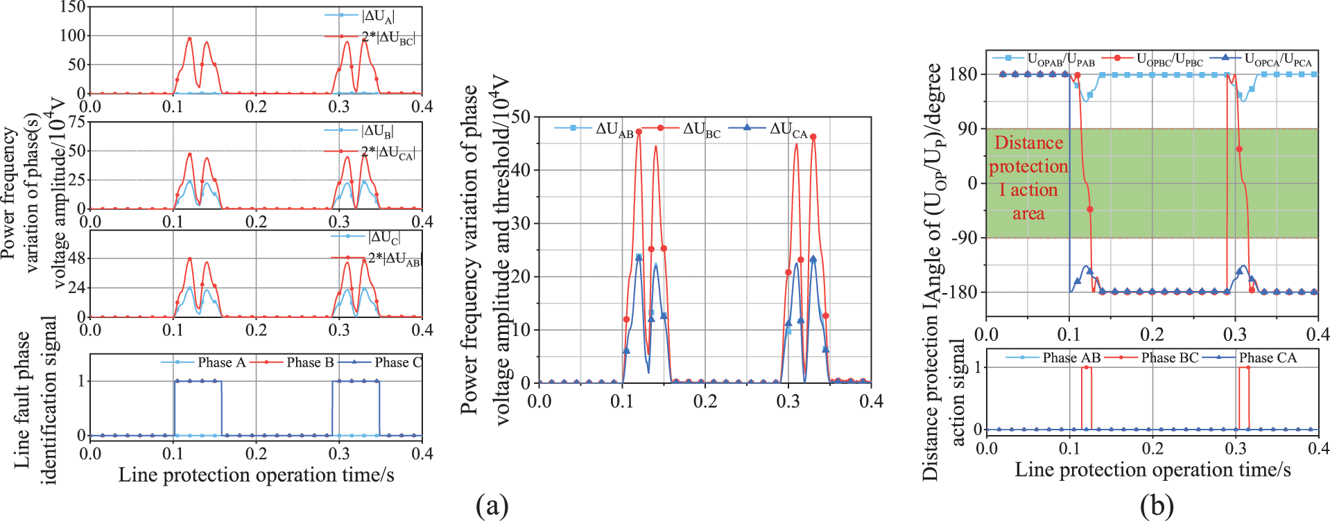
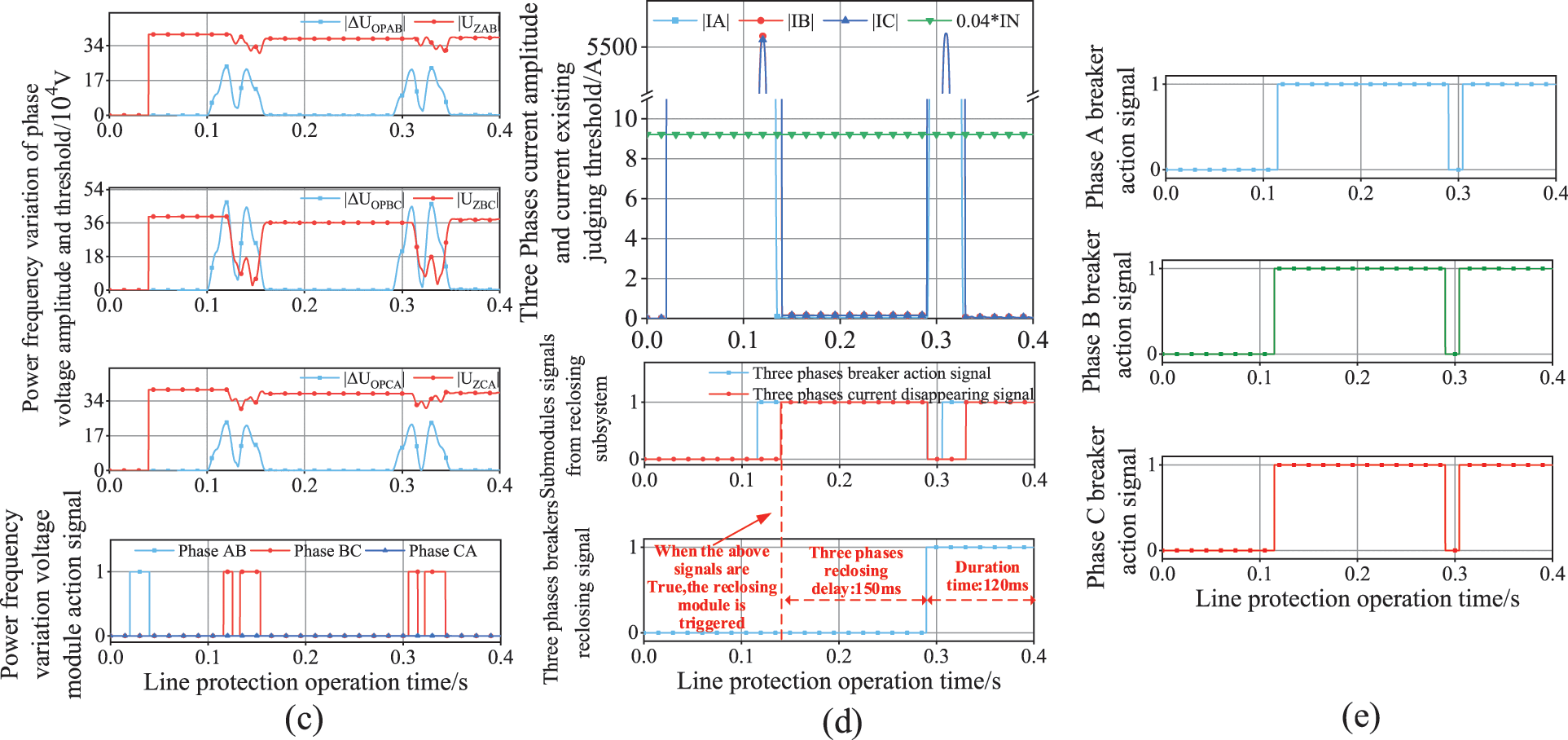
Figure 8: Simulation system action signal diagrams of two (B, C) phases short circuit fault
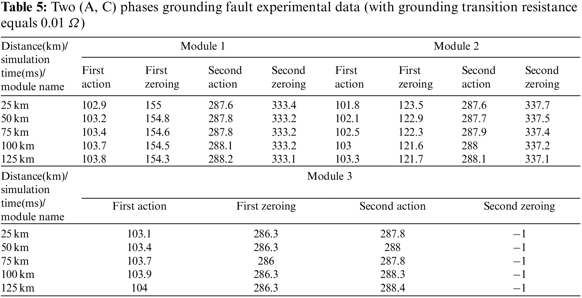
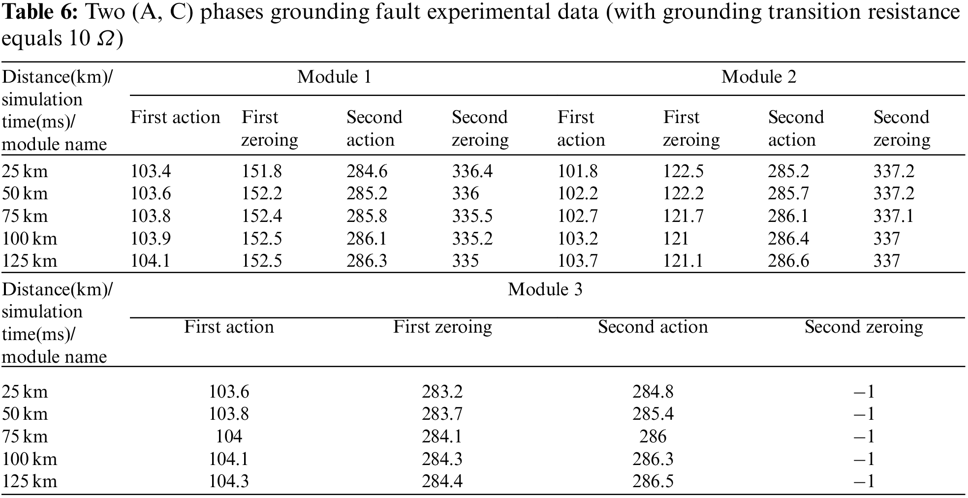
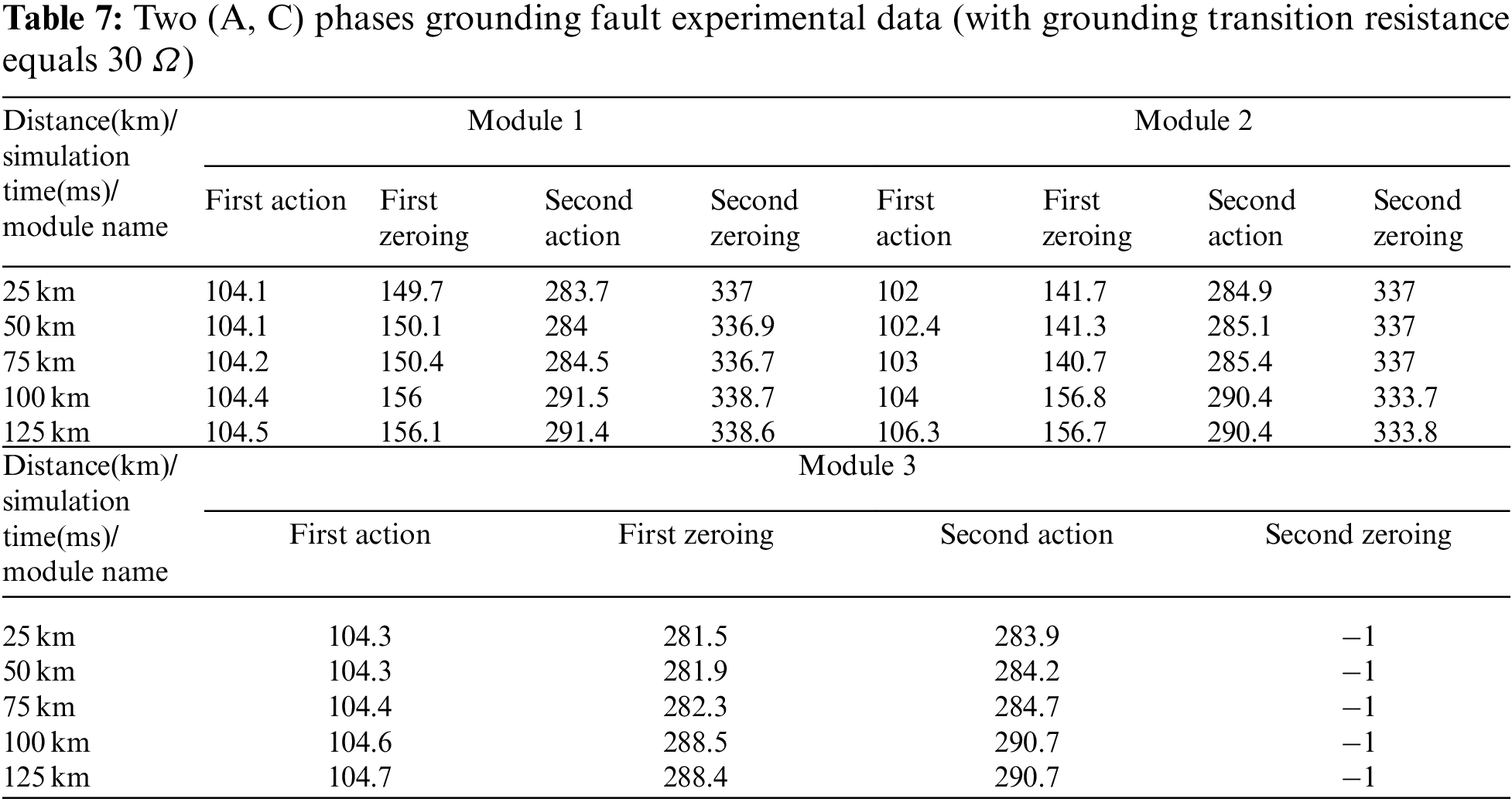
If the protection is longitudinal differential protection and AC metallic grounding fault occurs at 75 km away from the line head, the longitudinal differential protection can realize protection signal output and phase selection at the same time. When the fault happens, phase A and phase C power frequency variation differential protection module meets the action condition Eq. (9) at 103.7 ms, as shown in Figs. 9a and 9c, phase A and phase C steady conditions differential protection module Sections I and II respectively meets the action condition Eq. (10) at 103.4 and 102.5 ms, as shown in Figs. 9b and 9c. phase A and phase C zero-sequence differential protection module meets the action condition Eq. (11) at 103.2 ms, as shown in Figs. 9c and 9d. Since the steady condition differential protection module Section II and the zero-sequence differential protection module need to wait for 25 and 45 ms to output the signal, while the three phases breakers have already acted at 103.7 ms, these two modules usually do not participate in phase selection and signals sending. Power frequency variation differential protection module and steady conditions differential protection module Section I respectively returns to 0 at 154.6 and 134.5 ms. Combined with the condition that the three-phase current disappears at 136.0 ms, the breakers reclose at 286.0 ms, as shown in Fig. 9e. At this time the fault still exits, thus the 2 modules mentioned above both meet the action condition and send action signals at 287.8 ms, and the breaker will not reclose again, as shown in Fig. 9f, the above modules return to 0 at 333.2 and 313.2 ms. The faults happen at different places with different attributes yet using longitudinal differential protection subsystem to judge are also listed in Tables 5–7. Modules 1–3 respectively represents phase A, C longitudinal differential protection modules and three phases breakers. The “−1” means the module does not act. It can be seen that the longitudinal differential protection is not influenced by the transition resistance, and act faster than the grounding distance protection.
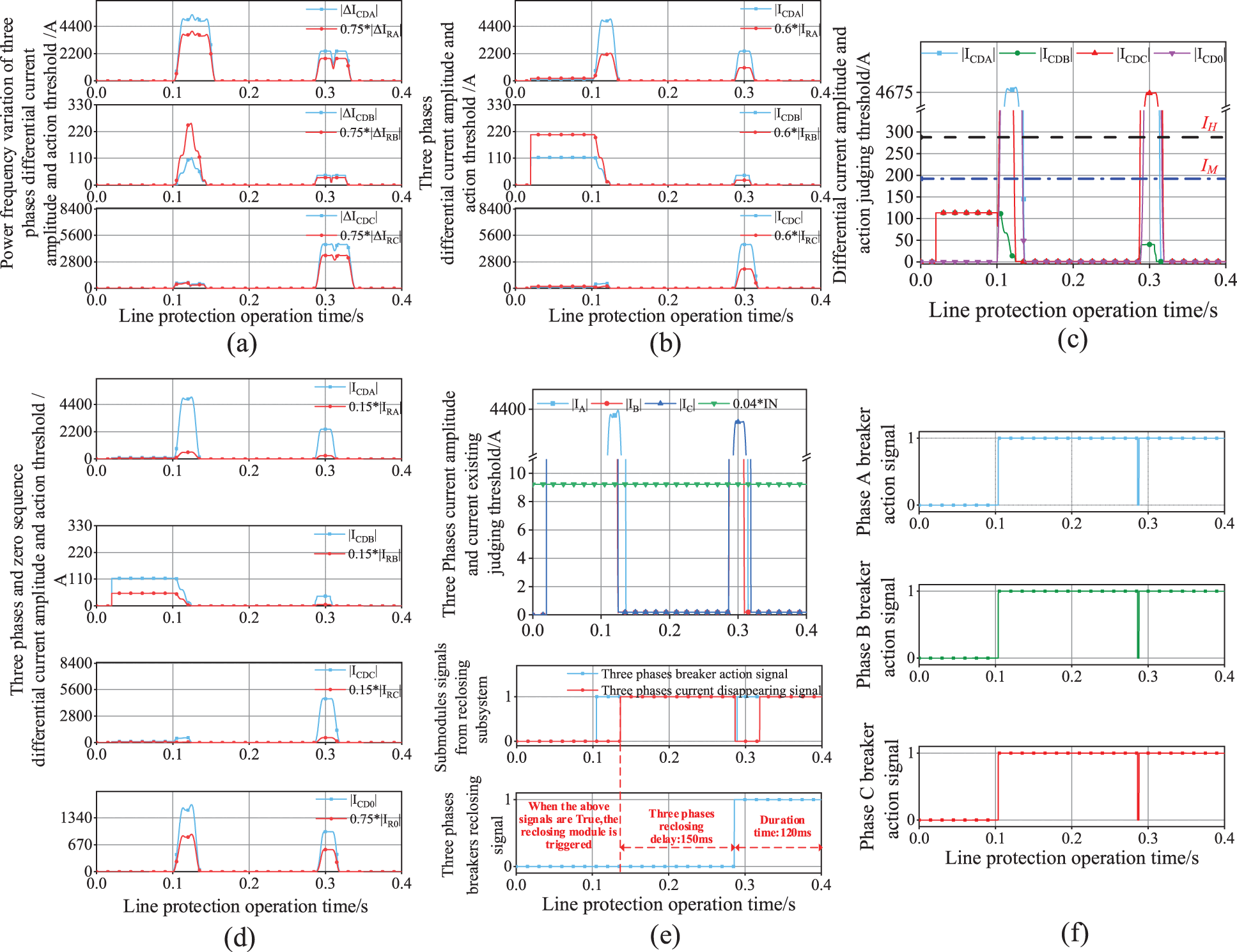
Figure 9: Simulation system action signal diagrams of phases A, C grounding fault within the protection zone
6.3 Grounding and Interphase Fault Outside the Protection Zone
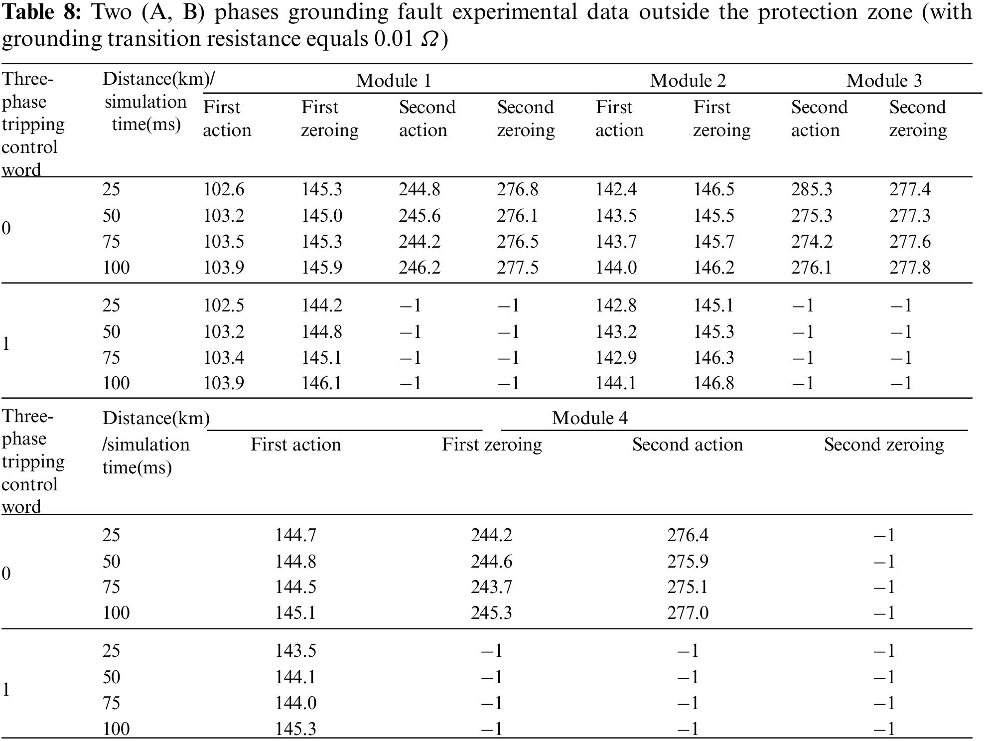
When a fault occurs outside the protection zone, if the quick-break protection in the next protection zone fails to startup, the action modules of this protection zone will operate, including the grounding and phase-to-phase distance protection II and the zero-sequence overcurrent protection II. This section quits the distance protection to verify the zero-sequence overcurrent protection subsystem ability to act accurately when a fault occurs outside the protection zone. Since the zero-sequence overcurrent protection only make three phases breakers acting together, there is no need to judge the exact fault phase. When the zero-sequence three-phase tripping control word is not put into use and an AB-phase metallic grounding fault occurs at 25 km away from the line head. The phase selection module, including the phase selection of power frequency variation distance protection module and the zero-sequence/negative sequence current ratio (I0/I2A) phase selection module, sends out the phase selection action signal at 102.6 ms. At the same time, the zero-sequence current is judged in the zero-sequence protection module, after the setting delay time 40 ms of zero-sequence Ⅱ, the zero-sequence Ⅱ module sends out an action signal at 142.4 ms. After the tripping module receives the action signal of zero-sequence Ⅱ module and the action signal of phase selection module, it sends out a three-phase trip signal, the circuit breaker is disconnected at 144.7 ms, and the signal of each module is reset. Then reclose at 244.2 ms after the setting reclose time. After reclosing, the phase selection module and the zero-sequence acceleration module perform fault judgment. Then the zero-sequence acceleration module sends out zero-sequence acceleration trip signal after 30 ms delay, and the trip module directly performs three-phase trip again after receiving the signal. When the zero-sequence three-phase trip control word is turned on, the three-phase trip will be directly performed when a fault occurs, and the reclosing subsystems will be blocked. The AB-phase metallic grounding faults happen at different places using zero-sequence overcurrent protection II module to judge are also listed in Table 8. Module 1–4 respectively represent phase selection module, zero-sequence overcurrent protection II, zero-sequence acceleration module and three phases breakers. The “−1” means the module does not act. It can be seen that the zero-sequence overcurrent protection is capable of judging the fault outside the protection zone.
6.4 Open Phase Operation Faults
When the comprehensive reclosing mode is selected for protection, single-phase fault will cause single-phase tripping, and the circuit breaker will close after single-phase reclosing delay. However, in the process of single-phase disconnection, the single-phase ground fault will be removed and the line turn into two-phase operation, which may cause system non-full phase oscillation. If the non-fault phase has short circuit fault again at this time, the system will not be able to operate normally. The distance protection must be allowed by the positive signals from oscillation blocking element, otherwise the distance protection will be blocked and refuse to operate. In this paper, the system adopts the non-fault phase to phase current power frequency variation as the oscillation blocking element in open phase operation. During this period, if another line fault occurs, the three-phase circuit breaker will trip. The method flow is shown in Fig. 10.
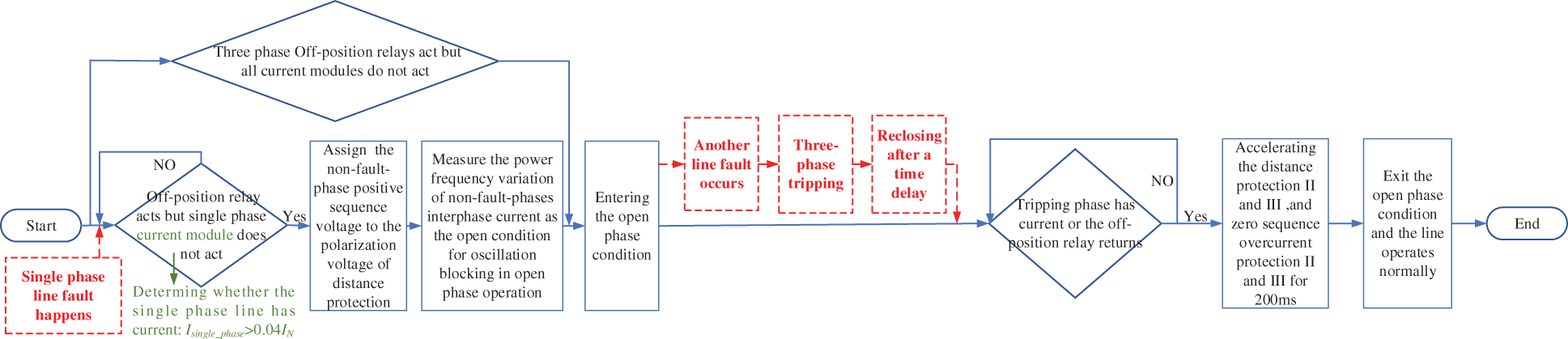
Figure 10: Simulation system processing flow chart of open phase operation faults
This paper designs that the phase-to-phase BC short circuit fault occurs during the open phase operation caused by the single phase A grounding fault within the protection zone. The occurrence time of the single phase A grounding fault is in the 100 ms of the total simulation time 500 ms, and the duration time of fault is 70 ms. The occurrence time of the BC phase-to-phase fault is in the 150 ms of the total simulation time 400 ms, and the duration time of fault is 200 ms. The action signals of the related modules are shown in the timeline in Fig. 11. According to the figures, When A the single phase A grounding fault occurs, the systems instantaneously cuts off the single-phase head-end breaker and non-full-phase oscillation blocking module is open at the same time. After another 100 ms, a phase-to-phase short circuit fault occurs, and three phases breakers are removed. The former fault first causes the reclosing module to send a signal after the single-phase reclosing time. Three phases breakers are closed while the fault still exists and then trips again. After that, three phases breakers will no longer reclose. The protection signal changes to 1 when it judges that the fault occurs.
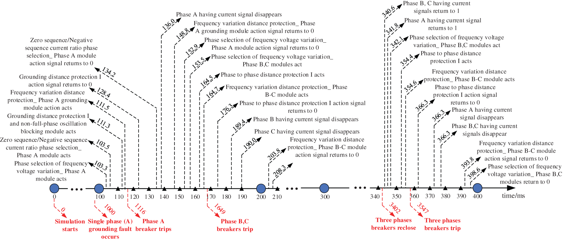
Figure 11: Simulation system action signals timeline of an open phase fault
6.5 Simulation Analysis of Protection Condition Prediction in the far Future
In this paper, the maintenance cycle is set to be 4 × 10⁴ h, and the interval between monitoring points is set to be 104 h. Then, the probability of the device remaining in condition 1 after running for 9 × 10⁴ h is shown in Fig. 12a. It can be seen that due to the recalculation of the transferring rate matrix at each observation point, the operation rejection rate and the mal-operation rate are further improved, resulting in a significant downward trend in the probability of the device in the normal condition-condition 1. Although the device is reset to condition 1 after the maintenance point, the probability of the device remaining in condition 1 will be significantly improved due to the incompleteness of the maintenance degree and the failure rate increasing with the operation period. Finally, the probability of the device remaining in condition 1 will decrease to 0.9497 when the maintenance time is 9 × 10⁴ h. In addition, the monitoring probability can further approximate the real probability if the monitoring point is increased. Fig. 12b shows the probability of condition 1 maintaining itself and transferring to conditions 3 and 8. Since each monitoring point will determine the condition of the device, and the probability of the device maintaining in condition 1 is the highest, the condition of the monitoring point device is calculated as condition 1. The initial value of the transferring probability will be reset to the unit matrix and calculate the transferring probability. The transferring probability curve of the condition 1 will increase sharply, and the corresponding probability curve of the transfer to the fault condition will decrease sharply. Before the aging of the device, if the protection action is normal and does not need to be transferred to the emergency maintenance condition 2, the probability of the device transferring to the normal condition 8 is the highest. The probability change of this period is consistent with the literature [17]. However, with the gradual aging of the device, the probability of the protection transferring to the fault conditions gradually exceeds that of transferring to conditions 8 and 2. As shown in Fig. 12b.

Figure 12: Simulation system action signal and line head end current recorded diagram of open phase oscillation fault within the protection area
When the maintenance is not considered, the malfunction probability interval of condition 1 can be calculated as [0.9817, 0.9443]. Based on this range, the warning threshold of condition 1 probability can be set, and emergency maintenance could be arranged when the probability reaches this value, as shown in Fig. 12c. However, it can be seen from the above descriptions that the maintenance can only update the protection to condition 1, and cannot completely solve the failure rate caused by aging. Therefore, the probability exit threshold can be designed based on this, such as 0.96, that is, if the probability of condition 1 is lower than a certain threshold, and it has been repaired twice, the protection is decommissioned. At this time, the operating life of the device is about 9.902 years. At this time, even if the maintenance is arranged, the probability of condition 1 will drop sharply below the exit threshold, which meets the actual device.
In order to improve the condition monitoring ability of relay protection device when complex external system fault or internal software and hardware abnormality occurs, and the capability to warn the wrong actions of the protection device in the far or near future in advance. It is imperative to strengthen the reliability and the predictability of relay protection device condition monitoring method.
However, the traditional condition monitoring method in the substation has the problems that the monitoring is not timely and the early warning ability is limited, the automatic condition monitoring method lacks the online action probability prediction function independent of the actual device. This paper designed a set of relay protection device conditions monitoring and action rehearsal system based on numerical simulation., which including the logic twinned subsystem and the software and hardware conditions subsystem. Case analysis shows that the system can realize 0.1 millisecond-level action deduction for normal grid faults within and outside the protected area, monitor the operation conditions of physical device in real-time based on sampling accuracy, and predict wrong action probability in the far future, which effectively improves the efficiency of automatic operation and maintenance for relay protection device.
This paper still has the following problems: the operation logic of the logic simulation system is mainly based on the design of NARI PCS-931-A device, and its scalability is not strong at present; In addition, the software and hardware condition prediction matrix based on Markov chain has not considered the influence of line operation mode, and its relationship with specific software and hardware faults is not clear in the far future. In the next step, this paper will further expand the protection logic and provide selection interface to improve the adaptability of the simulation system to protection devices from different manufacturers; in addition, based on the operating conditions of external 220 kV lines, the state prediction matrix will be continuously expanded and refined, and the relationship between different wrong action probabilities and specific hardware or software failure types will be further studied.
Funding Statement: This work was supported by the Science and Technology Program of State Grid Corporation of China (No. kj2020–056).
Conflicts of Interest: The authors declare that they have no conflicts of interest to report regarding the present study.
References
1. Zhang, B. H. (2004). Strengthen the protection relay and urgency control systems to improve the capability of security in the interconnected power network. Proceedings of the CSEE, 7, 5–10. DOI 10.13334/j.0258-8013.pcsee.2004.07.001. [Google Scholar] [CrossRef]
2. Shi, Y. K., Jiang, Z. C., An, C. R. (2016). Research on practical conditions evaluation of protection device in smart substation. Power System Protection and Control, 44(10), 119–125. DOI 10.7667/PSPC151166. [Google Scholar] [CrossRef]
3. Chen, X. T. (2015). Hidden fault diagnosis of intelligent substation relay protection and new methods of system reconfiguration. (M.S. Thesis). Chongqing University, China. [Google Scholar]
4. Chen, G. P., Wang, D. L., Qiu, Y. T., Wang, S., Qi, X. W. et al. (2017). Challenges and development prospects of relay protection technology. Automation of Electric Power Systems, 41(16), 1–11+26. DOI 10.7500/AEPS20170219004. [Google Scholar] [CrossRef]
5. Jun, F. M., Liu, H. Y., Dong, L. C. (2015). Research and application of relay protection automatic test system for smart substation. Power System Protection and Control, 42(1), 40–44. DOI 10.7667/j.issn.1674-3415.2015.01.007. [Google Scholar] [CrossRef]
6. Wu, X., Zhang, J. H., Hu, L. W., Huang, Z. (2012). Method of operational risk assessment on transmission system cascading failure. Proceedings of the CSEE, 32(34), 74–82. DOI 10.13334/j.0258-8013.pcsee.2012.34.012. [Google Scholar] [CrossRef]
7. Chen, W. H., Jiang, Q. Y., Cao, Y. J. (2006). Risk assessment of power system cascading failure considering hidden failures of protective relaying. Power System Technology, 13, 14–19+25. DOI 10.3321/j.issn:1000-3673.2006.13.003. [Google Scholar] [CrossRef]
8. Liu, K., Huang, M. H., Li, Y. Q., Liu, W., Chen, Q. P. et al. (2020). Research on online operation method for protective relay of smart substation. Power System Protection and Control, 48(7), 58–65. DOI 10.19783/j.cnki.pspc.190617. [Google Scholar] [CrossRef]
9. Liu, K., Huang, M. H., Li, Y. Q., Chen, Z. G., Zeng, G. H. W. et al. (2017). Online monitoring method for relay protection in smart substation based on conditions message relationships. Modern Electric Power, 34(6), 85–91. DOI 10.19725/j.cnki.1007-2322.2017.06.014. [Google Scholar] [CrossRef]
10. Liu, H. F., Chen, H., Jiang, J. L., Yin, J. H. (2017). Design and implementation of automatic monitoring system of secondary device based on D5000 platform. Power System and Clean Energy, 33(11), 39–45. DOI 10.3969/j.issn.1674-3814.2017.11.007. [Google Scholar] [CrossRef]
11. Li, G., Huang, J. D., Ni, C. K., Fan, Z. F., Li, Y. et al. (2018). Discussion on the construction scheme of intelligent substation on-site protection simulation test system. Power System Protection and Control, 46(17), 152–157. DOI 10.7667/PSPC171203. [Google Scholar] [CrossRef]
12. Bi, P. (2020). Relay protection simulation experiment platform based on signal adaptive THD reconstruction. (M.S. Thesis). Shandong University of Science and Technology, China. [Google Scholar]
13. Yu, Q., Bi, P., Wu, C. J. (2020). Relay protection simulation experiment platform based on signal wavelet preprocessing. Science Technology and Engineering, 20(12), 4760–4769, 2020. DOI 10.3969/j.issn.1671-1815.2020.12.022. [Google Scholar] [CrossRef]
14. Huang, J. G., Yu, N., Lin, N. X., Yuan, L. T. (2019). Model on the action logic time-sequence modeling of remote duplicate configuration smart-protection integration center. Electrical Measurement & Instrumentation, 56(7), 54–60, 2019. DOI 10.19753/j.issn1001-1390.2019.07.009. [Google Scholar] [CrossRef]
15. Zong, Z. (2019). Key technology of relay protection fault diagnosis in smart substation based on disturbance excitation. Electrical Measurement & Instrumentation, 56(21), 63–69. DOI 10.19753/j.issn1001-1390.2019.021.011. [Google Scholar] [CrossRef]
16. Xu, C. B., Wang, Y. L., Zhao, L. J., Gao, J. P., Huang, L. et al. (2018). Fuzzy comprehensive evaluation of intelligent substation relay protection system state based on information trend prediction and combination weighting. Electric Power Automation Equipment, 38(1), 162–168. DOI 10.16081/j.issn.1006-6047.2018.01.024. [Google Scholar] [CrossRef]
17. Li, H., Lin, X. N., Yu, K., Zhao, H., Li, Z. T. et al. (2018). Based on continuous time markov chain prediction model of action behavior of relay protection device. Proceedings of the CSEE, 38(S1), 121–128. DOI 10.13334/j.0258-8013.pcsee.171150. [Google Scholar] [CrossRef]
18. Xu, Y., Lu, G. X., Xu, X. M., Chen, Z. (2015). Research on the reliability of the distance protection using power frequency variable components. Power System Protection and Control, 43(20), 51–57. DOI 10.7667/j.issn.1674-3415.2015.20.008. [Google Scholar] [CrossRef]
19. Tan, J., Xiao, H., Li, Y., Zhang, A. L., Li, Y. H. (2015). Study on influence of transformer magnetizing inrush current on the line zero-sequence overcurrent protection by transient simulation. Power System Protection and Control, 43(19), 149–153. DOI 10.7667/j.issn.1674-3415.2015.19.025. [Google Scholar] [CrossRef]
20. Wang, J. Q., Xu, Y., Peng, Y. N., Ye, Y. B. (2019). Estimation of reliability parameters of protective relays based on grey-three-parameter weibull distribution model. Power System Technology, 43(4), 1354–1360. DOI 10.13335/j.1000-3673.pst.2018.0982. [Google Scholar] [CrossRef]
21. Den, L. (2012). Simulation and analysis system for transmission line relay protection (M.S. Thesis). Hunan University, China. [Google Scholar]

Figure A1: Logic design of distance protection subsystem
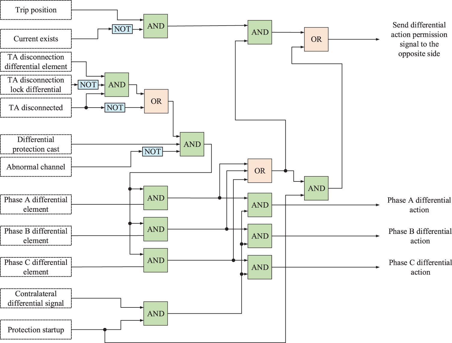
Figure A2: Logic design of longitudinal differential protection subsystem
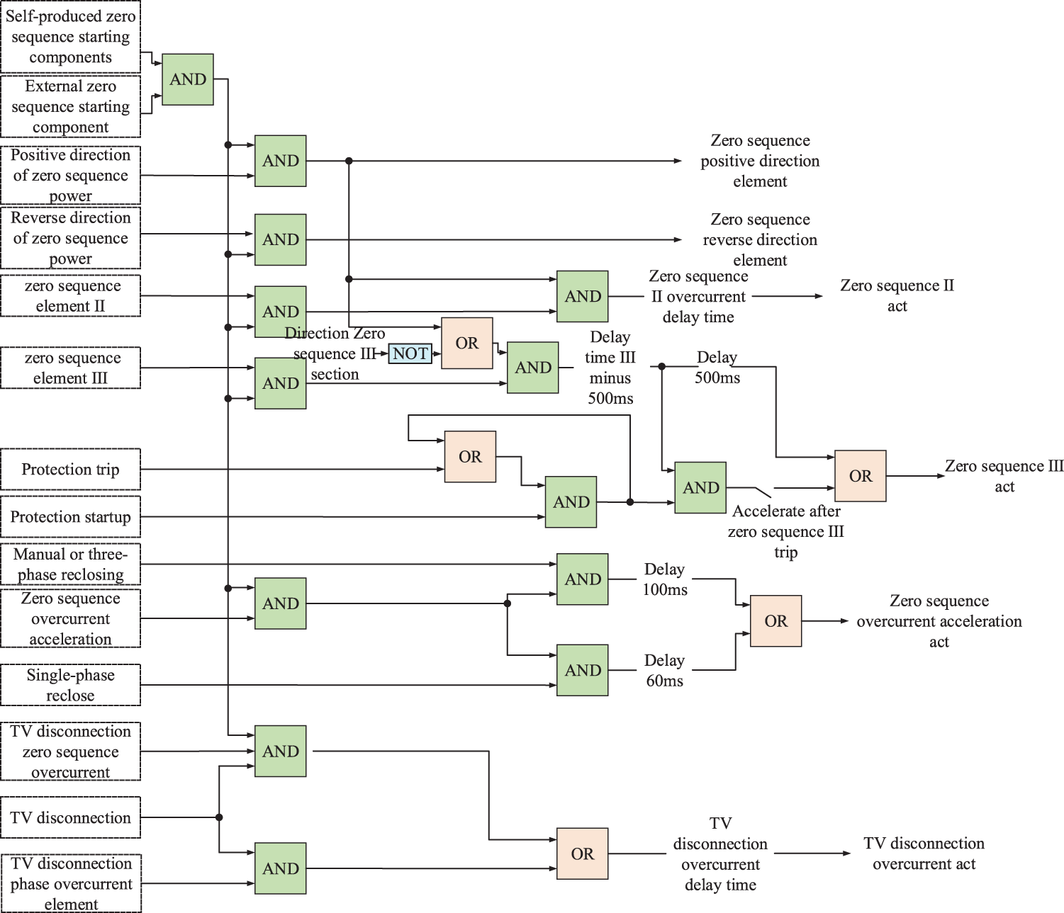
Figure A3: Logic design of zero-sequence overcurrent protection subsystem
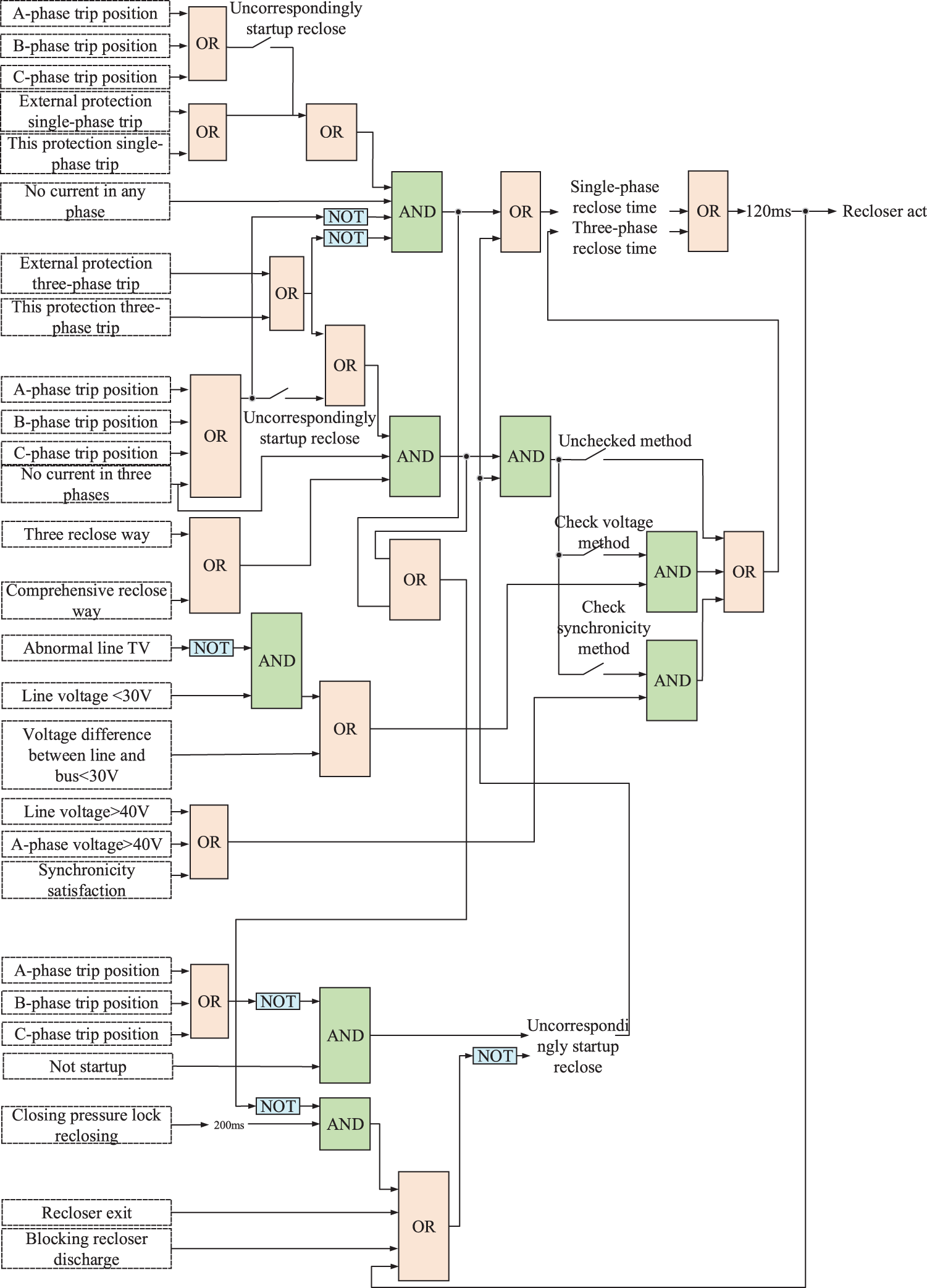
Figure A4: Logical design of reclosing subsystem

Figure A5: 220 kV line protection system tripping design
 | This work is licensed under a Creative Commons Attribution 4.0 International License, which permits unrestricted use, distribution, and reproduction in any medium, provided the original work is properly cited. |