| Energy Engineering |
DOI: 10.32604/ee.2022.019526
ARTICLE
Numerical Study and Economy Analysis of Two Heated Crude Oil Pipelines Laid in One Ditch
1National Engineering Laboratory for Pipeline Safety, Beijing Key Laboratory of Urban Oil and Gas Distribution Technology, China University of Petroleum (Beijing), Beijing, 102249, China
2Shanxi Natural Gas Co., Ltd., Taiyuan, 030031, China
*Corresponding Author: Yongtu Liang. Email: liangyt21st@163.com
Received: 18 September 2021; Accepted: 23 December 2021
Abstract: In this paper, the transportation economy of two heated crude oil pipelines laid in one ditch is analyzed by taking into account the influence of operating temperature, interval between two pipelines, and distance between two heating stations on the heating energy consumption. To analyze the transportation economy, the two heated crude oil pipelines laid in one ditch are simulated under four operating conditions based on an unstructured finite volume method. Compared with laying two crude oil pipelines separately in two ditches, the results attest notably higher soil temperature, meaning reduced heat dissipation of each pipeline by laying two pipelines in one ditch. It is inferred that for the same desired oil temperature at the inlet of the next heating station, laying two pipelines in one ditch requires lower oil temperature at the outlet of heating station, indicating decreased energy cost at the heating station and improved transportation economy. Then economy analysis of four configurations of laying two pipelines in one ditch is performed. By comparing the results of four conditions, the interval between two pipelines of 1.2 m is found to save the energy most efficiently, which is as large as 26.6% compared with that of laying two pipelines in two separate ditches. In addition, narrowing the pipeline interval and extending the distance between heating stations is beneficial to save heating energy. This study is expected to provide valuable guidance for operation optimization of heated crude oil pipelines.
Keywords: Heated crude oil pipeline; laying two pipelines in one ditch; numerical simulation; thermal effect; economy analysis
In the past decades, there have been ever increasing exploitation of oil and gas. While at the same time, a large number of existing crude oil pipelines are close to or beyond its service life, leading to the decrease of oil transportation capacity. Laying two crude oil pipelines in the same ditch has been accepted as an effective means to improve the transportation efficiency in petroleum transportation engineering [1–4]. In addition, laying two crude oil pipelines in one ditch can significantly save the investment of pipeline construction. Besides, a large percentage of crude oil produced in China has high wax content and pour point, which needs to be heated during transportation to guarantee smooth flow [5–8]. Due to the temperature difference between heated oil in the pipeline and soil surrounding the pipeline, heat is transferred from the oil to the soil and then dissipated into the atmosphere. When the two hot crude oil pipelines are laid in one ditch, the soil around pipelines is heated under combined effect of two pipelines, and the thermal field of two crude oil pipelines interact with each other, leading to decrease heat dissipation along the pipeline and reduce heating energy consumption for smooth transportation. Thus, laying two heated crude oil pipelines in one ditch can reduce the operating cost and promote a better economic performance.
The technology of either laying the crude oil pipeline and product oil pipeline in one ditch, or laying the crude oil pipeline and natural gas pipeline in one ditch has been extensively studied by researchers. For example, through numerical simulations, Yu et al. [9–11] compared the thermal fields of two oil pipelines laid in the same ditch with that laid separately, and the thermal effect of product oil pipeline on the crude oil pipeline in one ditch was revealed. Ling et al. [12,13] investigated on the influence of product oil pipeline on hot crude oil pipeline under different operation parameters, especially the impact on the oil temperature was the main concern in their work. Zhang et al. [14] conducted research to analyze the effect of product oil pipeline on crude oil pipeline transporting hot and cold crude oil in sequence. Wang et al. [15] studied the configuration of laying natural gas pipeline and oil pipeline in one ditch. Under various intervals between two pipelines, the temperature difference and thermal characteristics of laying natural gas pipeline and oil pipeline in one ditch were compared with that of laying two pipelines separately in two ditches. For Shanshan-Lanzhou pipeline in China, Wu et al. [16] calculated the temperature drop of hot oil pipeline and product oil pipeline laid in one ditch during a shutdown period. It was reported that in February, a shutdown of 72 h was acceptable and the heating station along the pipeline was reasonably arranged; when the interval between hot oil pipeline and product oil pipeline was 1.2 m, the influence of product oil pipeline on the shutdown of hot crude oil pipeline is negligible. Readers of interest can also refer to [17–22] for more information. From the literature review, it is known that previous researches have devoted great effort to studying the thermal impact by laying two pipelines in one ditch, however, the investigation on economic benefits by laying two pipelines in one ditch is still insufficient and more effort is needed.
In this paper, the technology of laying two hot crude oil pipelines in one ditch is carefully studied under four representative operating conditions, and the energy consumption and transportation economy under different operating temperatures are analyzed quantitatively. The results are expected to provide data support for economy analysis. In addition, this research will be valuable reference for the application of laying two pipelines in one ditch in petroleum transportation engineering.
2 Mathematical Model and Numerical Methods
The computational domain of laying a hot crude oil pipeline in the ditch is shown in Fig. 1a, where the soil domain thermally affected by the pipeline is restricted within 10 m from the pipeline, thus the size of the computational domain is −10 m ≦ x ≦ 10 m and −10 ≦ y ≦ 0 m. While when laying two hot crude oil pipelines in one ditch, considering that the soil is thermally affected by both two pipelines, the computational domain is determined as Fig. 1b to ensure an equilibrium heating effect of the two pipelines on the surrounding soil. In Fig. 1b, the oil pipeline 1 locates at exactly the y-direction symmetry axis of the domain, while the oil pipeline 2 is located at the left side of pipeline 1 with a L0 distance (interval) along the x axis.

Figure 1: Sketch map of buried hot crude oil pipelines
Comprehensively considering the interaction between crude oil, wax deposition layer, steel layer, anti-corrosion coating, soil, and air, the mathematical model of oil pipeline transportation is established based on the following assumptions [9–12]: (a) The temperature of crude oil only depends on time and axial position along the pipeline; (b) Soil is treated as an isotropic homogeneous medium; (c) The temperature drop of soil along the pipeline axial direction is ignored, and thus the three-dimensional heat transfer can be simplified as the two-dimensional one.
Based on above assumptions, the governing equations including the continuity equation, momentum equation, and energy equation for the pipeline transportation of crude oil can be written as,
where ρ is the crude oil density, kg/m3; A is the cross-section of pipeline, m2; τ is the time, s; V is the mean velocity of oil flow, m/s; z is the axial coordinate, m; g is the acceleration of gravity, −9.81 m/s2; f is the Darcy friction coefficient; s is the location of elevation, m; u is specific internal energy of crude oil, J/kg; h is the specific enthalpy of crude oil, J/kg; D is the internal diameter of pipeline, m; T is the temperature of crude oil, °C; α is the angle between pipeline axis and horizontal direction; p is the average cross-section pressure of the flow, Pa; q is the dissipated heat of crude oil on unit pipe wall area in unit time, W/m2.
On the basis of Eqs. (1)∼(3), the heat exchange equation of oil flow can be derived as,
where Cp is the specific heat capacity at constant pressure of crude oil, J/(kg⋅°C); β is the expansion coefficient of crude oil, °C−1.
The heat transfer equation of wax deposition layer, pipe wall and anti-corrosion coating is described as,
where i = 1, 2, 3 respectively denote the wax deposition layer, pipe wall and anti-corrosion coating; r is the radial coordinate, m; θ is the circumferential coordinate; ρirepresents the density of the ith layer, kg/m3; Ci corresponds to the specific heat capacity of ith layer, J/(kg⋅°C); Ti is the temperature of ith layer, °C; λi is the heat conductivity coefficient of ith layer, W/(m⋅°C).
The boundary condition (third type of condition or Robin condition) is presented as follows:
where T0 is the temperature of internal pipe wall, °C; α0 is the heat transfer coefficient from oil flow to pipe internal wall, W/(m2⋅°C).
According to the laws of thermodynamics, the heat transfer equation of soil can be formulated as,
where ρs, Cs and λs are respectively the density, specific heat capacity and heat conductivity coefficient of soil, kg/m3, J/(kg⋅°C), and W/(m⋅°C). Ts is the temperature of soil, °C.
The corresponding boundary conditions are set as,
where αa is the heat transfer coefficient from the ground surface to the air, W/(m2⋅°C); Ta is the air temperature, °C; Tn is the soil temperature at the buried depth of H, °C.
In this study, the hydraulic and thermal characteristics of the two buried crude oil pipelines laid in one ditch are simulated using an unstructured finite volume method [10,11]. The computational domain is discretized and then the location of each node and corresponding control volume are determined. Specifically, the unstructured triangular grid is used to discretize the soil region, as shown in Fig. 2; and the polar grid is applied to discretize the wax deposition layer, steel layer, and anti-corrosion coating, with the enlarged details presented in Fig. 3 [23]. The hot oil pipelines are discretized by one-dimensional girds, with the computational node starting from the outlet of the upstream heating station (node 1), ending at the inlet of the downstream heating station (node n), as shown in Fig. 4. Readers of interest can refer to [11,23] for more details regarding the grid system.

Figure 2: Unstructured triangular grid of the soil domain

Figure 3: Polar grid for wax deposition layer, steel layer and anti-corrosion coating

Figure 4: Grid of the pipeline
Based on the field data, the calculation parameters that have appreciable influence on the oil temperature along pipeline are selected and set carefully in numerical cases in this part. These parameters include the pipeline diameter, distance between two heating stations, interval between two pipelines, pipeline buried depth, soil temperature at pipeline buried depth, heat conductivity coefficient of soil, throughput of two oil pipelines, and oil temperature at the outlet of heating station. The values of these parameters are presented in Table 1 and the reasons for setting these values are based on following considerations.

(a) Pipeline diameter: the pipeline diameter in the fields of China generally ranges from 377 to 1016 mm in diameter. Accordingly, the oil pipeline 1 in Fig. 2 is selected as Ф720 mm × 8 mm and the oil pipeline 2 is set as Ф813 mm × 10.3 mm; (b) Distance between two heating stations: it is the distance from the outlet of a heating station to the inlet of the neighboring downstream heating station, which is set as 120 km in this study; (c) Interval between two pipelines: with a small interval between two pipelines, the construction in the field is difficult. While, if the interval between two pipelines is extremely large, laying two pipelines in one ditch is degraded to be similar with that laying two pipelines in two ditches separately. Thus, the interval between two pipelines is generally restricted between 0.7–1.6 m. In this study, the interval of 1.2 and 1.6 m is selected; (d) Throughput of two pipelines: in engineering practice, there is a range of economic velocity for oil transportation, which is within 1–2 m/s. In present numerical cases, the economic velocity is set as 1.5 m/s and then the throughput of two oil pipelines can be determined; (e) Pipeline buried depth (namely the distance between the center of the pipeline and the ground surface): from the perspective of construction feasibility and construction convenience, the pipeline buried depth should be within 1.2–1.6 m. Generally, a larger pipeline buried depth is favorable for a larger pipeline diameter. In present study, the pipeline buried depth is set as 1.6 m; (f) Soil temperature at pipeline buried depth: it is commonly around 0°C in winter, while in summer it is about 20°C. At different locations, the soil temperature at pipeline buried depth is different because of the various external environments. In this work, the average soil temperature at pipeline buried depth in winter is selected, which is set as 1.6°C; (g) Heat conductivity coefficient of soil: according to the geological characteristics of China, the heat conductivity coefficient of soil is generally in the range of 1.2–2.6 W/(m⋅°C), basically it is set as 1.4 W/(m⋅°C) in present numerical cases.
The other physical parameters used in the simulation are presented as follows: the crude oil density is 860 kg/m3, the heat conductivity coefficient of oil is 0.1378–0.0002 T W/(m⋅°C); the specific heat capacity and the viscosity of crude oil is a function of oil temperature [24]; the expansion coefficient of crude oil is 7.8 × 10⁻⁴°C−1. The density of wax deposition layer, pipe wall and anti-corrosion coating layer is 1200, 7800, 1000 kg/m3, respectively; the specific heat capacity of wax deposition layer, pipe wall and anti-corrosion coating layer is 2000, 465, 1400 J/(kg⋅°C), respectively; the heat conductivity coefficient of wax deposition layer, pipe wall and anti-corrosion coating layer is 0.19, 48, 0.15 W/(m⋅°C), respectively. The soil density is 1800 kg/m3, the specific heat capacity of soil is 980 J/(kg⋅°C). The heat transfer coefficient from the ground surface to the air is 20.6 W/(m2⋅°C); the air temperature is set as 10°C.
Except for above parameter settings, the oil that transported in the two pipelines is waxy crude oil with the freezing point of 32°C. The thickness of anti-corrosion coating and wax deposition of the pipeline is set as 4 mm. According to “Code for design of oil transportation pipeline engineering (GB50253-2014)”, the oil temperature at the inlet of heating station should be 3°C higher than the freezing point of crude oil. When two pipelines transport the same waxy crude oil, provided the freezing point is 32°C, the oil temperature at the inlet of heating station should not be lower than 35°C, which is referred as the allowable lowest inlet oil temperature. Then the oil temperature at the outlet of heating station can be determined accordingly.
3.2 Simulation Results and Analysis
For comparison, the following numerical cases are considered: (a) the oil pipelines 1 and 2 are laid separately in two ditches, namely standard case; (b) the oil pipelines 1 and 2 are laid in one ditch with the interval of 1.2 and 1.6 m, namely the test cases. To make sure that the oil temperature along the pipeline is higher than the allowable lowest inlet oil temperature, the oil temperature at the outlet of heating station for oil pipeline 1 is not lower than 51°C, while that for oil pipeline 2 is not lower than 48°C.
Table 2 presents the oil temperature at the outlet and inlet of heating station for above numerical cases. The comparison indicates that by laying the oil pipelines 1 and 2 in the same ditch, the oil temperature at the outlet of heating station is at least 2°C higher than that of standard case laying two oil pipelines in two separate ditches. In addition, it can be found that with smaller interval between the two oil pipelines, the increase of oil temperature against that of standard cases is more obvious.

To clarify the influence of pipeline laying mode on the economy of pipeline operation, firstly the soil temperature fields at the inlet and outlet of a heating station are presented, as shown in Figs. 5 and 6. In addition, the heat flux at ground surface and the oil temperature distribution along the pipeline are provided in Figs. 7 and 8.

Figure 5: Soil temperature field at the inlet of a heating station


Figure 6: Soil temperature field at the outlet of a heating station

Figure 7: The heat flux along pipeline

Figure 8: Oil temperature along the pipeline
From Figs. 5 and 6, it can be clearly seen that when the oil pipelines 1 and 2 are laid in the same ditch, the soil temperature around especially between the two oil pipelines is obviously higher than that of laying oil pipelines 1 and 2 separately in two ditches. In addition, narrower interval between the two oil pipelines leads to the higher temperature of surrounding soil, the soil temperature with the interval of 1.2 m is higher than that with the interval of 1.6 m in this study. This phenomenon can be attributed to the combined heating effect of the two oil pipelines in the same ditch on the surrounding soil, which is enhanced as the interval between the two oil pipelines is narrowed. It can also be found that the pipeline laying mode has slight influence on the soil temperature far from the two oil pipelines. In other words, whether laying two oil pipelines in the same ditch or in two separate ditches, the soil region far from the two oil pipelines has approximately similar temperature distributions and the thermal impact of pipeline laying mode is negligible at these regions. Thus, the assumption that the thermal effect of oil pipelines on the soil is within 10 m from the pipelines is reasonable, and the computational domain of this study has been properly determined.
Fig. 7 compares the heat flux along the pipeline for both laying two oil pipelines in two separate ditches and laying two oil pipelines in one ditch. It can be clearly seen from Figs. 7a∼7b that any of the oil pipelines laid in one ditch has a less heat dissipation than that laid separately in two ditches. Fig. 7c demonstrates that the system has smaller heat dissipation in case of laying two oil pipelines in one ditch. As the interval between the two oil pipelines in one ditch increases, the heat dissipation along the oil pipeline also increases, so does the absorbed heat by the atmosphere, while the soil temperature around the pipelines decreases.
Fig. 8 depicts the oil temperature along oil pipelines laid in the same ditch and laid separately in two ditches. It can be observed that under the same parameter setting and same oil temperature at the outlet of a heating station, the oil temperature along the pipeline for laying two oil pipelines in one ditch is higher than that of laying two oil pipelines separately in two ditches. Besides, the oil temperature profiles present obvious dependence on the interval between the two pipelines, demonstrating slower oil temperature drop along the pipeline and higher oil temperature at the inlet of a heating station as the interval is reduced. Therefore, compared with laying two oil pipelines in two separate ditches, the oil temperature at the outlet of a heating station can be reduced to a certain extent when two oil pipelines are laid in the same ditch, and this is a means to save the energy consumption at heating stations.
Above numerical analysis indicates that the pipeline laying mode has significant influence on the heat dissipation in the transportation of hot crude oil. To explore the influence of pipeline laying mode on the economy of pipeline operation quantitatively, the following four numerical cases are presented and corresponding parameter setting is shown in Table 3: (a) Test case 1: two hot oil pipelines are laid in one ditch with the outlet-of-station oil temperature identical with the standard case, being respectively 51°C and 48°C for the two pipelines; (b) Test case 2: two hot oil pipelines are laid in one ditch, and pipeline 1 has the same outlet-of-station oil temperature 51°C with that of pipeline 1 in the standard case, while pipeline 2 has the lower outlet-of-station oil temperature than the standard case, by which the oil temperature at the inlet of the downstream heating station is exactly same with the allowable lowest oil temperature. (c) Test case 3: two hot oil pipelines are laid in one ditch, and pipeline 2 has the same outlet-of-station oil temperature with that of pipeline 1 in the standard case. The outlet-of-station oil temperature of pipeline 1 is reduced and is exactly the same with the allowable lowest oil temperature. (d) Test case 4: two hot oil pipelines are laid in on ditch, and the oil temperature at the outlet of heating stations of the two pipelines is reduced and is exactly same with the allowable lowest oil temperature.
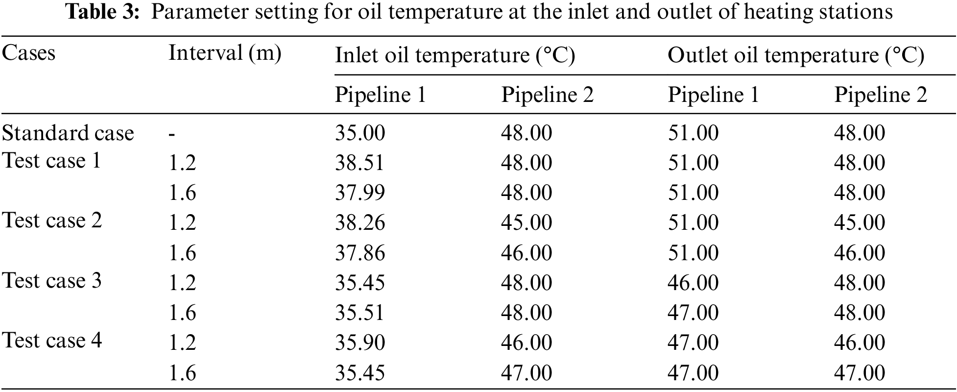
Through the hydraulic and thermal simulation of laying two hot oil pipelines in one ditch in the four numerical cases, the oil temperature at the inlet and outlet of heating stations of the two pipelines is presented in Table 3. In real pipeline operation, considering that the oil temperature at the outlet of a heating station can be accurately controlled, the calculated oil temperature at the outlet of heating stations is presented as integers. Table 3 indicates that compared with the standard case and test case 1, the outlet-of-station oil temperature of at least one pipeline in cases 2–4 declines to a certain extent, among which the case 4 has the largest decrease. Take case 4 as an example, the oil temperature along the pipeline is shown in Fig. 9. It can be clearly seen from Fig. 9 that although the oil temperature at the outlet of heating stations of the two pipelines decreases at the same time, the oil can still be smoothly and safely transported in the pipeline and heating station. Thus laying two pipelines in one ditch can not only ensure good economy but also guarantee the reliability and safety of pipeline operation. In addition, it can also be found that the thermal interaction of two pipelines laid in one ditch depends on the interval between two pipelines. Under the same parameter setting, the smaller interval yields greater thermal influences, lower required oil temperature at the outlet of heating stations, less energy dissipation along the pipeline and therefore better economy of pipeline operation. However, in real engineering of pipeline construction, many other factors such as the field construction condition, should be taken into account to determine a reasonable interval between two pipelines laid in one ditch.

Figure 9: The oil temperature along pipeline in case 4
Assuming that there is a heating station that receives the crude oil with high pour point from the two pipelines laid in one ditch, the oil temperature at the inlet of this heating station is presented in Table 3. To smoothly and safely transport the crude oil from this heating station to next heating station, the crude oil needs to be heated to the required temperature. That is to say, the oil temperature at the outlet of this heating station should reach a certain value as shown in Table 3.
In the economy analysis, the heating station uses transported crude oil as the heating fuel, and the efficiency of heating furnaces is set as 0.85. To heat the crude oil, the required heat energy can be calculated by,
where Q represents the heat required for heating crude oil, J; m is the mass of crude oil to be heated, kg;
The heating energy consumption in the numerical cases presented in Table 3 can be calculated according to Eq. (11), as presented in Table 4. It can be clearly seen from Table 4 that the test case 4 with the interval between the pipelines being 1.2 m consumes the least heating energy, i.e., the 26.6% of heating energy consumption can be saved compared with that of the standard case (laying two pipelines separately in two ditches).

3.4 Increasing the Distance between Heating Stations
With the development of pipeline construction technologies, saving construction and operation costs and extending the distance between heating stations have been the economical pursuit in pipeline construction. Table 5 presents the oil temperature at the inlet and outlet of heating stations with the distance between heating stations being 240 km under various calculation conditions. The similar conclusions can be obtained from Table 5 with Table 2.

The economy analysis of laying two hot oil pipelines in one ditch with the distance between two neighboring heating stations of 240 km is presented in Table 6. It can be found that compared with laying two hot oil pipelines separately in two ditches, laying two pipelines in one ditch can save at most 29.9% energy consumption when the distance between heating stations is extended to 240 km. In addition, compared with laying two pipelines in one ditch when the distance between heating stations is 120 km, extending the distance between two heating stations to 240 km can further gain 20.1% more energy saving.

In this paper, the economy of two hot crude oil pipelines laid in one ditch is analyzed by considering the influence of operating temperature, interval between two pipelines, and distance between two heating stations on the heating energy consumption. Using the unstructured finite volume method and finite difference method, two hot crude oil pipelines laid in one ditch are numerically simulated. The economy benefits of laying two hot pipelines in one ditch are analyzed by comparing the four numerical cases (laying two hot pipelines in one ditch) with standard case (laying two hot pipelines separately in two ditches). The main conclusions of this study can be summarized as follows:
(1) Compared with laying two hot oil pipelines separately in two ditches, laying two pipelines in one ditch can significantly reduce the oil temperature at the outlet of heating stations and save the energy consumption for heating the oil. The technology of laying two hot oil pipelines in one ditch is beneficial to energy conservation. Thus for two hot oil pipelines in engineering practice, it is recommended to bury the two hot oil pipelines in one ditch to save energy.
(2) With the increase of pipeline interval, the heating impact of the two hot oil pipelines laid in one ditch on the surrounding soil will be weakened, and the energy saving will decrease as well. Thus the interval between two hot oil pipelines should be determined carefully.
(3) When the distance between two adjacent heating stations is doubled, the required oil temperature for smooth and safe transportation at the outlet of heating stations will increase, however, the energy saving will increase to 20.1% compared with that with the distance between two neighboring heating stations being 120 km. Therefore, the set of distance between two adjacent heating stations should strike a balance between the temperature at the outlet of heating stations and the overall energy saving.
Funding Statement: The authors received no specific funding for this study.
Conflicts of Interest: The authors declare that they have no conflicts of interest to report regarding the present study.
References
1. Tao, W. Q. (2020). Recent advances in numerical heat transfer. China: Science Press. [Google Scholar]
2. Wang, Q. K., Zhang, Z. W., Shi, Y., Li, R. L. (2011). Development status of the parallel laying technology in underground oil & gas pipelines. Oil & Gas Storage and Transportation, 30(1), 1–4. DOI 10.6047/j.issn.1000-8241.2011.01.001. [Google Scholar] [CrossRef]
3. Zhao, X. M. (2012). Numerical calculation of the temperature field of double laying in one ditch with petroleum transmission pipeline (Ph.D. Thesis). Northeast Petroleum University, China. [Google Scholar]
4. Bau, H. H., Sadhal, S. S. (1982). Heat losses from a fluid flowing in a buried pipe. International Journal of Heat and Mass Transfer, 25(11), 1621–1629. DOI 10.1016/0017-9310(82)90141-7. [Google Scholar] [CrossRef]
5. Zhang, J. J., Zhang, W. K., Yu, B. (2011). An efficient algorithm of the proper orthogonal decomposition for the restart computation of buried heated crude pipelines. Acta Petrolei Sinica, 32(1), 167–179. DOI 10.7623/syxb201101029. [Google Scholar] [CrossRef]
6. Li, C. J., Li, B. W. (2001). Numerical analysis of heated crude oil pipeline at shutdown. Oil & Gas Storage and Transportation, 20(7), 28–31. DOI 10.6047/j.issn.1000-8241.2001.07.008. [Google Scholar] [CrossRef]
7. Ai, M. Y. (2000). An analogous calculation on the thickness of wax deposition for buried hot oil pipeline. Oil & Gas Storage and Transportation, 19(1), 13–16. DOI 10.6047/j.issn.1000-8241.2000.01.005. [Google Scholar] [CrossRef]
8. Li, C. J. (1997). Thermal calculation of buried oil pipeline. Journal of Southwest Petroleum Institute, 19(1), 79–84. DOI 10.3863/j.issn.1000-2634.1997.01.016. [Google Scholar] [CrossRef]
9. Yu, B., Ling, X., Zhang, J. J., Wang, Y. (2007). Study on laying technology of products pipeline along with hot crude pipeline in one ditch. Acta Petrolei Sinica, 28(5), 149–152. DOI 10.7623/syxb200705029. [Google Scholar] [CrossRef]
10. Yu, B., Lin, M. J., Tao, W. Q. (1999). Automatic generation of unstructured grids with delaunay triangulation and its application. Heat and Mass Transfer, 35(5), 361–370. DOI 10.1007/s002310050337. [Google Scholar] [CrossRef]
11. Yu, B., Wang, Y., Zhang, J. J. (2008). Thermal impact of the products pipeline on the crude oil pipeline laid in one ditch–the effect of pipeline interval. International Journal of Heat and Mass Transfer, 51, 597–609. DOI 10.1016/j.ijheatmasstransfer.2007.04.032. [Google Scholar] [CrossRef]
12. Ling, X., Wang, Y., Yu, B., Zhang, J. J., Da, X. et al. (2008). Thermal analysis of the new technology of crude oil pipeline and products pipeline laid in one ditch. Engineering Science, 10(11), 30–36. DOI 10.1016/j.ijheatmasstransfer.2007.04.032 [Google Scholar] [CrossRef]
13. Ling, X., Wang, Y., Yu, B., Zhang, J. J., Wang, K. et al. (2009). Thermal analysis of two pipelines laid in one ditch in Xinda pipeline in China. Journal of Engineering Thermophysics, 30(2), 299–301. DOI 10.3321/j.issn:0253-231X.2009.02.034. [Google Scholar] [CrossRef]
14. Wang, Q. K., Yu, B., Sun, C. Z., Shi, Y., Zhang, J. J. et al. (2012). Thermal impact of the parallel laying of oil/pipelines. Acta Petrolei Sinica, 33(2), 320–326. DOI 10.7623/syxb201202022. [Google Scholar] [CrossRef]
15. Wang, Q. K., Yu, B., Sun, C. Z., Zhang, Z. W., Zhang, J. J. et al. (2011). Comparison study on the thermal impact of two types of laying technologies with double pipelines in one ditch. Journal of Engineering Thermophysics, 32(5), 787–790. DOI 10.7623/SUN:GCRB.0.2011-05-018. [Google Scholar] [CrossRef]
16. Wu, Q., Chen, B. D., Rao, X. (2011). Simulation and analysis on shutdown process of the heated crude oil pipelines laid in one trench. Oil-Gas Field Surface Engineering, 30(3), 22–24. DOI 10.3969/j.issn.1006-6896.2011.3.010. [Google Scholar] [CrossRef]
17. Yu, B., Wang, Y. (2007). Model studies thermal effects of liquid pipeline collocation. Oil & Gas Journal, 105(18), 54–56. [Google Scholar]
18. Cui, X. G., Zhang, J. J. (2004). Determination of the thermal influence zone of buried hot oil pipeline on steady operation. Journal of the University of Petroleum, 28(2), 75–78. DOI 10.3321/j.issn:1000-5870.2004.02.021. [Google Scholar] [CrossRef]
19. Zhu, Y., Shi, J. H., Chen, G. M., Fu, J. M. (2016). Safety distance for leakage-induced explosion of long-distance parallel buried gas pipelines. Oil & Gas Storage and Transportation, 35(6), 591–595. DOI 10.6047/j.issn.1000-8241.2016.06.004. [Google Scholar] [CrossRef]
20. Wang, M., Li, Q., Chi, K., Gao, H. (2015). Analysis of reasonable spacing for parallel laying of oil and gas pipelines. Petro & Chemical Equipment, 18(11), 62–65. DOI 10.3969/j.issn.1674-8980.2015.11.017. [Google Scholar] [CrossRef]
21. Zhang, Z. H., Li, K. F., Zhang, W. W., Zhang, L. M., Geng, X. M. (2013). Boundary conditions for temperature field simulation of buried parallel pipelines. Oil & Gas Storage and Transportation, 32(6), 601–603. DOI 10.6047/j.issn.1000-8241.2013.06.008. [Google Scholar] [CrossRef]
22. Wu, F., Li, X. Y., Zhang, Z. J. (2010). Influence of buried parameters for heat transfer of pipelines laid in one ditch. Oil & Gas Storage and Transportation, 29(11), 835–838. DOI 10.6047/j.issn.1000-8241.2010.11.009. [Google Scholar] [CrossRef]
23. Zhao, Y. (2017). Numerical analysis on the coupled mechanism of water, temperature and stress fields of frozen soil around a buried oil pipeline in cold regions (Master Thesis). China University of Petroleum (BeijingChina. [Google Scholar]
24. Yang, Y. H. (2006). Design and management of oil transportation pipeline. China: China University of Petroleum Press. [Google Scholar]
 | This work is licensed under a Creative Commons Attribution 4.0 International License, which permits unrestricted use, distribution, and reproduction in any medium, provided the original work is properly cited. |