| Energy Engineering |
DOI: 10.32604/ee.2022.020002
ARTICLE
Hierarchical and Distributed Optimal Control Strategy for Power and Power Quality of Microgrid Based on Finite-Time Consistency
1College of Automation & Electrical Engineering, Lanzhou Jiaotong University, Lanzhou, 730070, China
2Key Lab of Opt-Electronic Technology and Intelligent Control of Ministry of Education, Lanzhou Jiaotong University, Lanzhou, 730070, China
*Corresponding Author: Hao Liang. Email: lhlzjtu@163.com
Received: 28 October 2021; Accepted: 06 January 2022
Abstract: Droop control is one of the main control strategies of islanded microgrid (MG), but the droop control cannot achieve reasonable power distribution of microgrid, resulting in frequency and voltage deviation from the rating value, which needs the upper control link to eliminate the deviation. However, at present, most layered control requires a centralized control center, which excessively relies on microgrid central controller (MGCC) and real-time communication among distributed generation (DG), which has certain limitations. To solve the above problems, this paper proposes a hierarchical distributed power and power quality optimization strategy based on multi-agent finite time consistency algorithm (MA-FTCA). Firstly, based on the first layer droop control, MA-FTCA is applied to introduce frequency and voltage compensation to stabilize the system frequency and voltage at the rated value. Secondly, in the third layer, the MA-FTCA is adopted to estimate the total active power and total reactive power spare capacity of the system, to realize the reasonable distribution of active power and reactive power output of each DG according to its proportion of spare capacity when the system load side changes. The control strategy proposed in this paper adopts a completely distributed control method and does not need a centralized control center in each layer of control. Finally, MATLAB/Simulink simulation platform is used to verify the correctness and effectiveness of the proposed optimization strategy.
Keywords: Microgrid; finite time consistency; power distribution; hierarchical control
With the consumption of fossil fuel resources and the aggravation of environmental pollution, many renewable energy-based microgrids [1] have been rapidly developed under the impetus of the carbon neutrality strategy. The coordinated and stable control of distributed generation in microgrid is an important guarantee for the reliable operation of the system [2]. The problem of multi-DG coordination control has been paid more and more attention.
According to the leading network electrical connection, a microgrid can be divided into grid-connected types and islanded types. This paper mainly studies the microgrid in islanded types. The microgrid usually adopts droop control for distributed power sources when it operates in islanded types. However, due to the difference in line impedance between the inverters and the load in the actual system, it is not easy to achieve the ideal proportional distribution by a single use of droop control. The load will cause the system frequency and voltage to deviate from the rated value, and its power quality is poor. In order to eliminate the deviation caused by traditional droop control, it needs to be adjusted twice. The secondary control is usually divided into two control modes: centralized control and autonomous control. Mathew et al. [3–5] proposed a centralized control method. The centralized control method uses the microgrid central controller (MGCC) to collect the information of each node, and after the information is calculated and processed, the control instructions are issued to the MGCC. The primary controller in microgrid realizes secondary regulation. This control mode requires an efficient communication network. The loss of any link may cause the failure of the corresponding unit, resulting in system-level instability and poor system reliability. Chen et al. [6] proposed an improved droop control-based online identification to eliminate the deviation of reactive power distribution. Shaheen et al. [7,8] proposed an optimal strategy based on Jellyfish search algorithm (JFSA) and Manta ray foraging optimization algorithm (MRFOA), which is used for joint distribution system reconfiguration (DSR), distributed generation units (DGs) integration, and distribution static VAR compensators (SVCs) operation. The proposed methods are used for the dynamic operation of ADS in order to minimize losses and reduce emissions when considering chronic daily load conditions. Kulkarni et al. [9] proposed that the combination of improved droop control and virtual impedance control can improve the power distribution accuracy, but it cannot adapt to the change of line impedance, so the adjustment accuracy needs to be improved. Shreeram et al. [10] proposed an improved droop control scheme based on virtual impedance to reduce the complexity of the control mode. This control scheme reduces the current circulation and improves the accuracy of reactive power distribution. Mi et al. [11] used a reference voltage loop based on SOC information and Metropolis criterion to modify the droop coefficient to meet the adaptive coordinated allocation of load power by each DG. Taher et al. [12] proposed a novel hybrid meta-heuristic optimize technique to improve and stabilize the voltage secondary control layer, which is applied to the fractional-order fuzzy proportional integral differential controller in the case of fault autonomous three-phase AC microgrid. Although the number of parameters is increased, the stability of microgrid operation is guaranteed under this control mode. Given the decentralized distribution of microgrid DG and the diversity of control objectives and types, Li et al. [13–16] stratified microgrid according to functions and proposed a stratified control scheme to achieve system optimization. Taher et al. [17] proposed an improved model predictive control (MPC) strategy, which adopts layered control to solve the overcurrent problem in the operation of a faulty AC microgrid. Voltage control based on MPC and frequency control without communication event time is used respectively to optimize power quality. In addition, to avoid using a central controller in the system and the DG only exchanges information with its neighbor DG at the same time, the system is in sparse communication. Each DG can be regarded as an agent, and multi-agent technology is applied. The distributed control strategy is proposed in [18,19]. Further, based on distributed hierarchical control, the multi-agent consistency algorithm is adopted in [20,21] to optimize the voltage and frequency of the system, and the system reliability is greatly improved. The multi-objective optimization problem of system stability and economic operation can be simultaneously satisfied in [22]. Yu et al. [23] used an improved second-order consistency protocol for active power tracking control and frequency optimization control of each DG in the second layer. Ma et al. [24] proposed that each DG achieve constant frequency and constant power distribution through PI controller and adaptively control P-f droop characteristic curve after information interaction through consistency algorithm. The voltage and frequency deviation caused by droop control can be eliminated. The distributed quadratic control algorithm can only achieve asymptotic convergence. The convergence time of system response is not considered, so the convergence speed is slow, and the control accuracy is low.
Aiming at the problems of reasonable power distribution and frequency voltage optimization of islanded microgrid, and inspired by the MA-FTCA [25,26], this paper proposes a hierarchical distributed optimize strategy for power and power quality of islanded microgrid based on MA-FTCA. The second and third level adjustment is carried out based on droop control. Each DG is regarded as an agent, and the distributed algorithm is combined with the layered framework to calculate the state variables at each layer independently. This control method adopts a wholly distributed algorithm, effectively improving the disadvantage of centralized control with high dependence on the central node.
The rest of this article is arranged as follows. Section 2 introduces some basic knowledge, namely, droop control and multi-agent algorithm. Furthermore, Section 3 describes the layered optimization strategy in detail. In addition, the simulation verification is carried out in Section 4. In the end, the conclusions of whole paper can be shown in Section 5.
2 Droop Control and Multi-Agent Algorithm
Fig. 1 is the equivalent circuit diagram of two DG inverters running in parallel, where the output voltage is
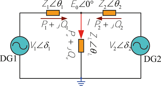
Figure 1: Inverter parallel equivalent circuit diagram
When the line inductive reactance is much greater than the line impedance, the line impedance can be ignored, then,
It can be seen from Eq. (2) that the active and reactive power output by the inverter mainly depends on the difference of power angle and voltage, so it can be equivalent to the equation shown in Eq. (3):
Among them,
2.2 Multi-Agent Finite-Time Consistency Algorithm
Generally, for a multi-agent system that contains n agents, each agent can be regarded as a point in the graph, and the communication between each agent can be regarded as an edge in the graph, which can be expressed as
The general consistency control protocol is:
where,
The protocol based on MA-FTCA designed in this paper is as follows:
where, the power parameter
Compared with the protocol proposed in Eq. (4), the algorithm has the characteristics of faster convergence and easier implementation with hardware circuits.
Theorem [26]: Assuming that the multi-agent system is unconnected and its corresponding Laplacian matrix must be a real symmetric matrix, then Eq. (6) can achieve the finite-time average consistency of the system, namely:
where,
3 Hierarchical Distributed Optimization Strategy
Due to the lack of inertia of the microgrid system, weak anti-disturbance ability, complex and diverse control links, a hierarchical microgrid control strategy is proposed for the overall control of the microgrid. The distributed control algorithm can achieve the purpose of global control because it only needs a small number of communication links and information exchange. It can better adapt to the needs of the microgrid in terms of economy and robustness, so it can be considered to be distributed control.
Because of the above, this paper proposes a hierarchical distributed optimize strategy based on MA-FTCA. Each DG only needs to exchange information with its neighboring DGs to achieve global consistency in a limited time. At the same time, because centralized optimize calculations are avoided, the speed of generating and issuing dispatching instructions is accelerated, which can better adapt to the dynamic needs of real-time dispatching of microgrids, effectively improve the speed, stability, and economy of system control. This strategy is based on droop control to perform two and three level adjustments. Its control goal is to achieve through hierarchical optimization that when the system load changes, each DG can achieve accurate and reasonable power distribution, the system frequency and voltage are stable at the rated value. This control method is divided into three layers.
The first layer is based on the primary control layer of droop control. In the primary control layer, decentralized droop control is adopted to achieve proportional distribution of power. At the same time, because droop control is a differential control, frequency deviation will occur. So, the frequency deviation will be further corrected in the second control layer.
The second layer is the droop control optimization layer based on frequency voltage compensation. The primary purpose is to eliminate the voltage frequency deviation caused by the first layer droop control. By introducing frequency voltage compensation in this layer, the frequency voltage of each DG can be maintained at the system rated value.
The third layer is the power distribution layer. When the system load changes, this layer will reasonably allocate the increase in active and reactive power according to the proportion of the total spare capacity of each DG when the system load changes. Make each DG run in a better working state, avoiding the phenomenon of uneven DG output.
The overall block diagram of the layered optimization strategy proposed in this paper is shown in Fig. 2. Since the reactive power-voltage control link is similar to the active power-frequency control link. It will not be described too much later.
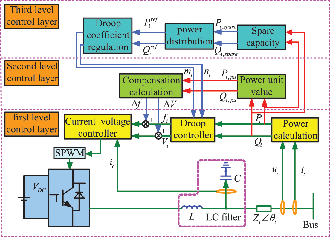
Figure 2: System power and frequency voltage control chart
3.1 Primary Droop Control Layer
In Eq. (3), it is assumed that the rated frequency and rated voltage amplitudes of all inverters are equal, satisfying:
And
where
According to Eq. (11), the output power of the inverter is inversely proportional to the droop coefficient, and the proportional distribution of the output power of the inverter can be realized by adjusting the value of the droop coefficient. However, the droop control is a differential adjustment, which will produce frequency and voltage deviation, so the system deviation needs to be corrected in the secondary control layer.
3.2 Frequency and Voltage Secondary Control Layer
Traditional droop control is affected by different line impedance and inverter parameters. In addition, when the system load changes, the power distribution imbalance between distributed power sources will occur. The system frequency and voltage cannot be adjusted in time, which affects the safe and stable operation of the MG. In this layer, frequency voltage compensation is introduced for correction. Firstly, the power per-unit value of each DG is used, and the mean value of the per-unit value is obtained using the MA-FTCA, and then the compensation value of the frequency voltage is obtained. This compensation is transferred to the droop control equation to maintain the frequency voltage at the system rating.
Sum both sides of Eq. (12):
where,
Eq. (13) is further simplified:
where,
By substituting the above
By substituting the final convergence value of Eq. (16) into Eq. (14), the frequency voltage compensation amount required by each DG can be obtained. Then, the compensation amount and the frequency voltage value obtained by the droop control end are added together to obtain the corrected frequency and voltage reference value.
Due to the diversity of DG in MG and the different maximum allowable power
Considering that the spare capacity of each DG is different in the actual situation, the average value is taken. First, the total active spare capacity
Specific estimation method: Firstly, each DG adopts the protocol of Eq. (5) and asymptotically converges to its average value in the case of local communication. Therefore, the
where,
Using Eq. (18) to calculate the convergence value as the estimated value of the average value
where,
In particular, by setting DG1 as the main distributed power supply, the load increase
In Eq. (20),
After the output increase
where,
Finally, the updated power reference value is substituted into Eq. (3) to adjust the droop coefficient. The updated droop coefficient is sent to the traditional droop control link to achieve accurate distribution of active and reactive power.
To sum up, Eqs. (17) and (21) can reasonably allocate the power of each DG of the system so that each DG can operate at the working point of the power reference value, meanwhile ensure that the frequency and voltage of the islanded microgrid can be stable at the rated value.
The overall flow chart of hierarchical distributed power and power quality optimization strategy control based on MA-FTCA is denoted in Fig. 3.
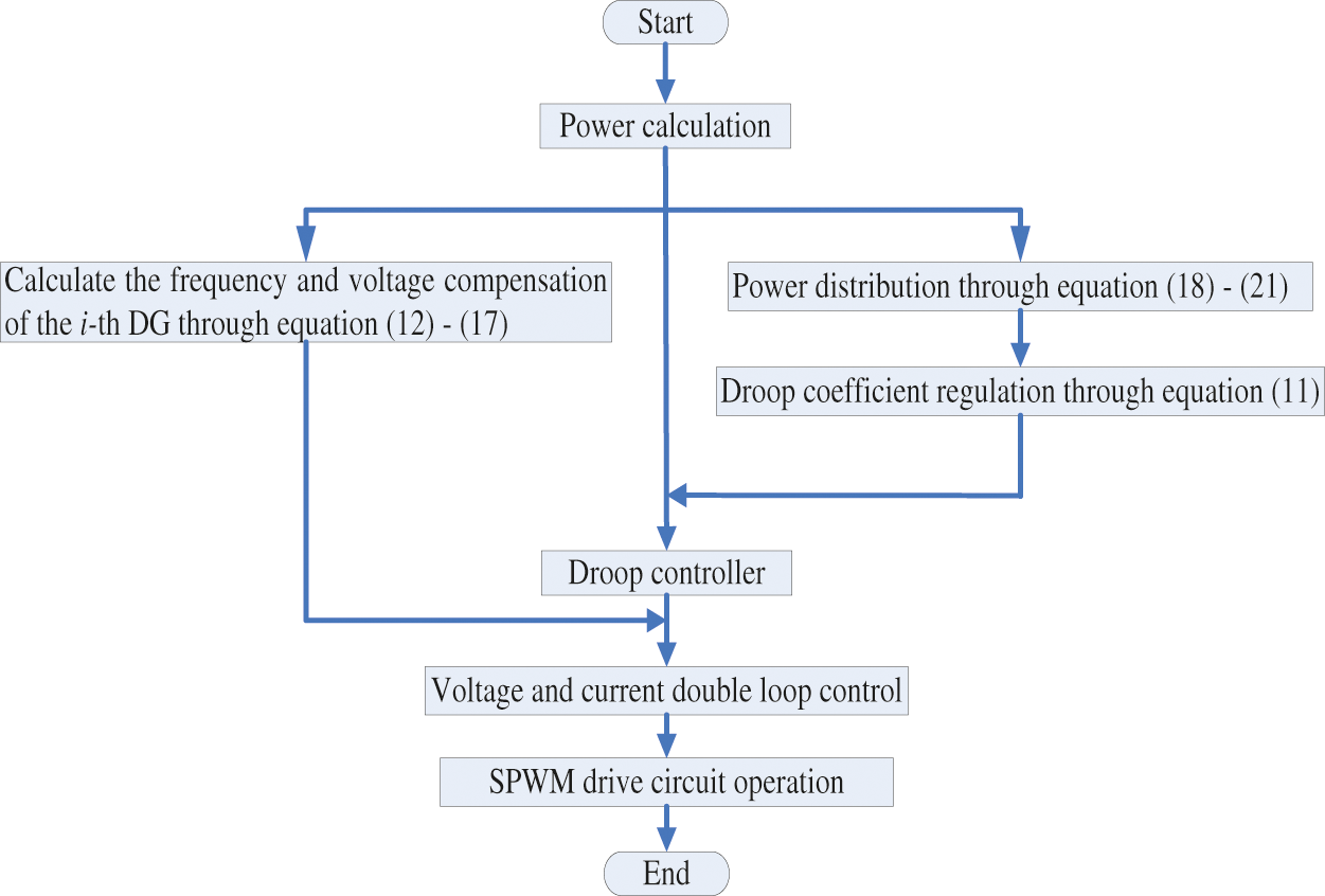
Figure 3: Distributed optimization control strategy overall flow chart
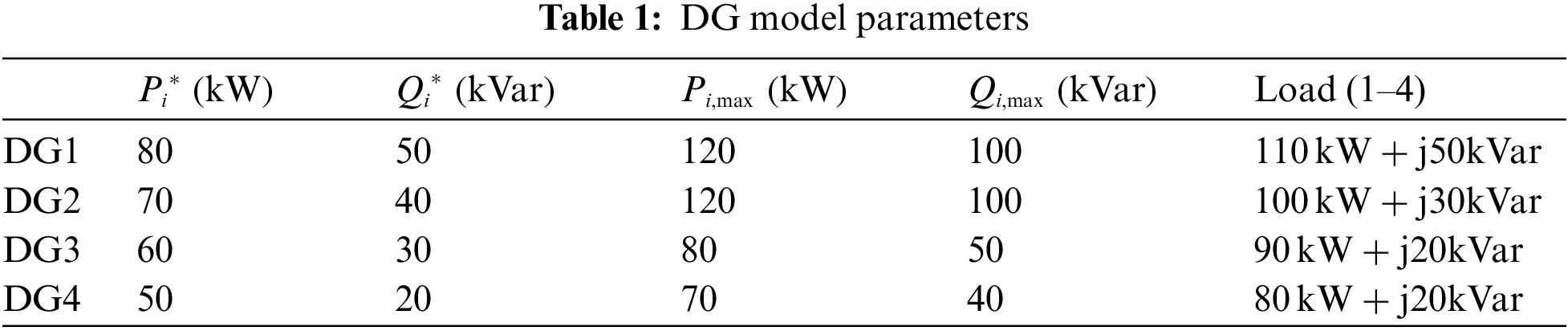
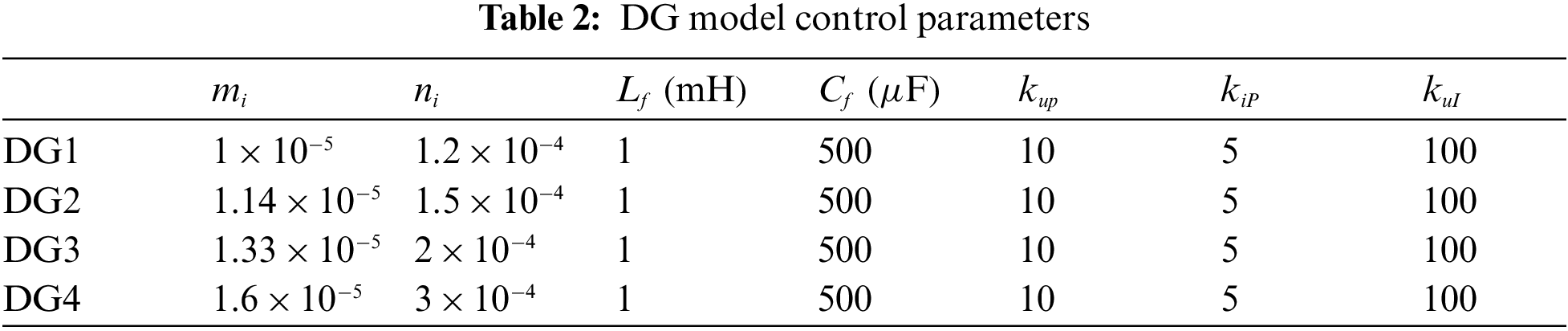
This section uses a 4-node MG system shown in Fig. 4 to simulate and verify the layered optimization strategy proposed above on the MATLAB/Simulink platform. The MG system is composed of 4 DGs. The simulation parameters and load of each DG are shown in Tables 1 and 2. When DG1 is designated as the main power supply, the measured value of load increase on the bus can be obtained directly through communication. The distributed communication network of the system, as shown in Fig. 4, is a loose network, which meets the algorithm requirements of Eq. (5), and its adjacency matrix is Eq. (22). Three examples are given to verify the proposed method.
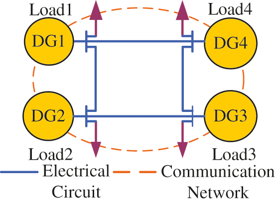
Figure 4: Microgrid system simulation model
In this calculation example, sudden change of load side is set to verify that the MG system model can still achieve reasonable power distribution of each DG and stable frequency and voltage of the system when the load side changes.
The simulation process is as follows: at 0 s, DG1∼DG4 drives the operation of Load1∼Load3, Load4 is put into the system at 2 s. The correctness and superiority of the optimization strategy proposed in this paper are compared with droop control. In addition, the time to reach the consistency is shortened by 60% compared with the general consistency.
In 0–2 s, Load1∼Load3 is put into the system. It can be seen from Figs. 5a and 5b that the active power distribution of the output of each DG is 92.3, 80.8, 69.2, and 57.7 kW when droop control is used alone. Each distributed power supply runs smoothly.
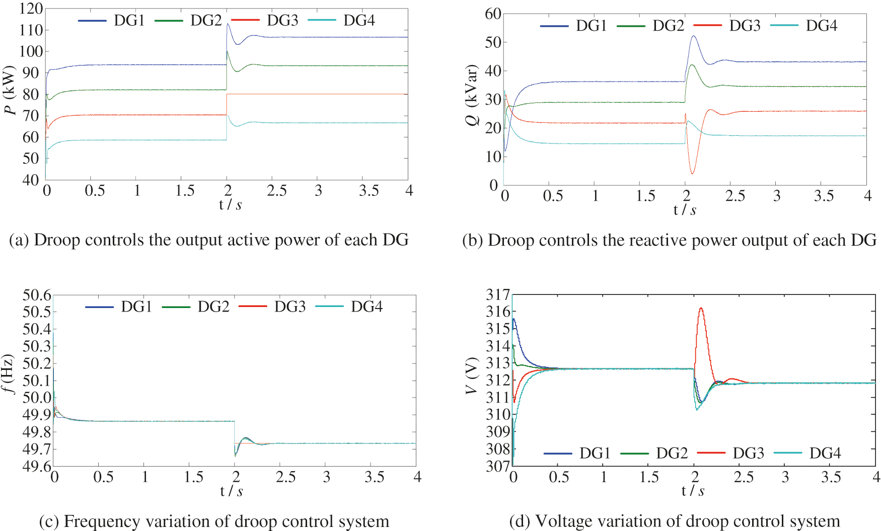
Figure 5: Simulation results with droop control
When Load4 is added to the system within 2 s, the system load changes, and the total active load increases from 300 to 380 kW. After 2 s, the actual active power output of each DG is 106.7, 93.3, 80, and 66.7 KW, respectively. The total active power output of the system was 346.7 kW, while the total active load requirement was 380 kW. That is, power supply and demand balance cannot be satisfied.
The active power output of DG3 is 80 kW, and it operates at the maximum power point. Long working time significantly impacts the efficiency and working life of the distributed power supply. Therefore, it is necessary to adjust the active power distribution and modify the droop coefficient according to the proportion of active power spare capacity.
Figs. 5c and 5d are simulation waveforms of system frequency and voltage. It can be seen from the figure that frequency and voltage drop are pronounced after Load4 is put into the system. Therefore, the single use of droop control cannot realize real-time power response and complete, accurate power distribution when the system fluctuates significantly. At the same time, it will cause the system frequency to deviate from the rated value in the case of significant load fluctuation, and the frequency should be compensated based on droop control.
4.2 Adopt the Optimization Strategy in This Paper
Based on the calculation example of droop control above, the droop control is continued to be adopted from 0 to 2 s, Load4 is connected to the system and put into the system at 2 s, and the second-third layer control links of the hierarchical distributed optimization strategy proposed in this paper are adopted. As Load4 is connected to the system, the load changes, and each distributed power supply interacts with each other to obtain the spare capacity information and optimize the control of each DG.
According to Fig. 6a, it can be seen that through the third power distribution layer, the increase in the output of the DG to the new load will be distributed in proportion to the size of the reserve capacity of each DG, as shown in Eq. (20), which are 116.9, 115.6, 78.8 and 68.6 kW. It can be seen from the figure that the output power of each DG does not exceed its maximum output power. The total output active power of distributed power is about 380 kW, which meets the balance of system power supply and demand. The output of each distributed power supply is more reasonable within the allowable error range, which verifies the effectiveness of the power distribution link.
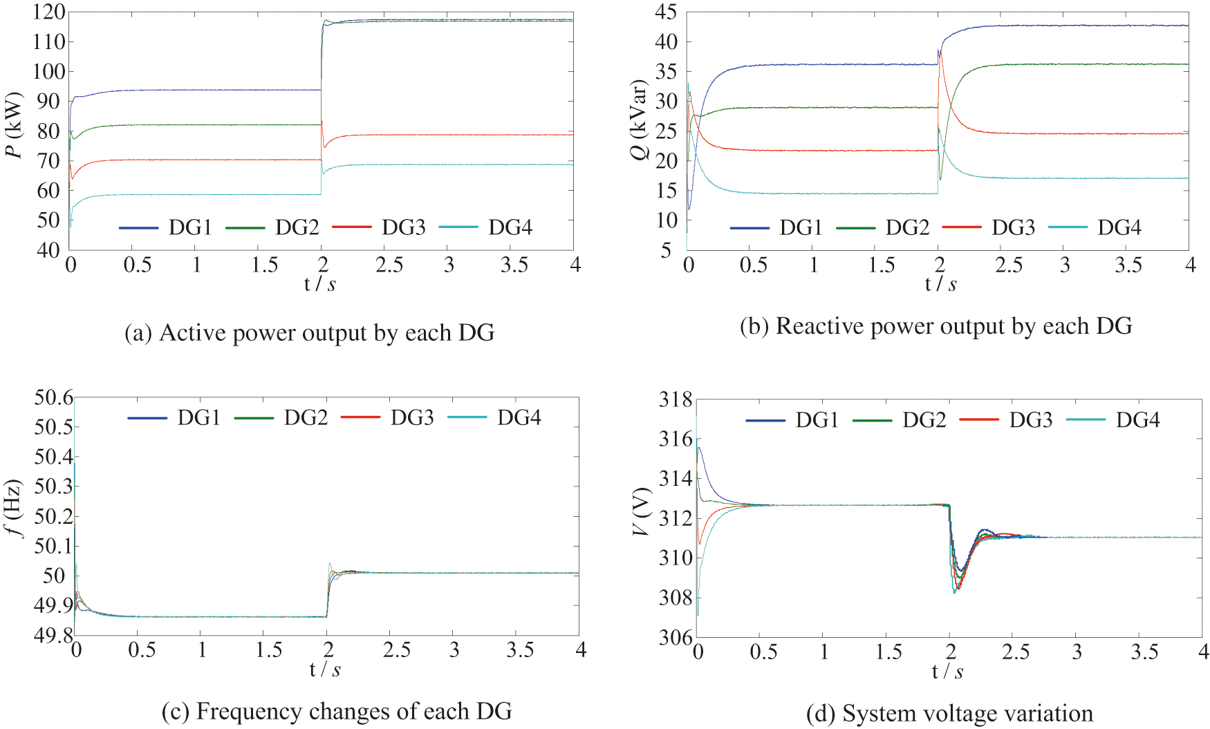
Figure 6: Simulation results with optimization strategy
Figs. 6c and 6d show the variation of frequency and node voltage of each DG. After the hierarchical optimization proposed in this paper is adopted at 2 s, the frequency rises briefly but stabilizes to the rated value 50 Hz after the frequency compensation is obtained by distributed algorithm, and the voltage drops and stabilizes to the rated value 311 V. Verify the effectiveness of the frequency compensation link.
Compared with the simulation analysis of droop control, it can be seen that in the case of only knowing the local and adjacent DG information, compared with the simulation process without distributed layered control strategy, frequency regulation and power distribution can better meet the operation requirements of the microgrid. The distributed optimization strategy proposed in this paper is adequate for power distribution and power quality optimization of islanded microgrids.
In addition, the optimization problem of reactive power is similar to that of active power, so we will not elaborate too much here.
4.3 Comparison of Consistency Algorithms
Fig. 7a shows the convergence of active-spare capacity obtained by the MA-FTCA protocol Eq. (5) adopted in this paper, which reaches a consistency value of 22.5 kW after about 1.34 s.
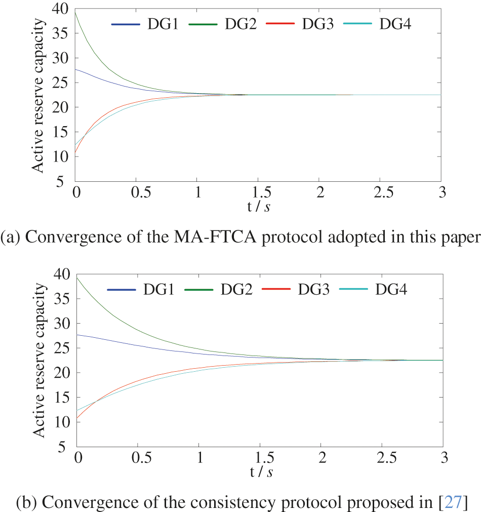
Figure 7: Convergence comparison of two consistency algorithms
Fig. 7b shows the simulation results obtained using the consistency protocol Eq. (4) in [27], which reached consistency after about 2.84 s.
By comparing Figs. 7a and 7b, it can be seen that the convergence time of the MA-FTCA algorithm proposed in this paper is nearly 50% faster.
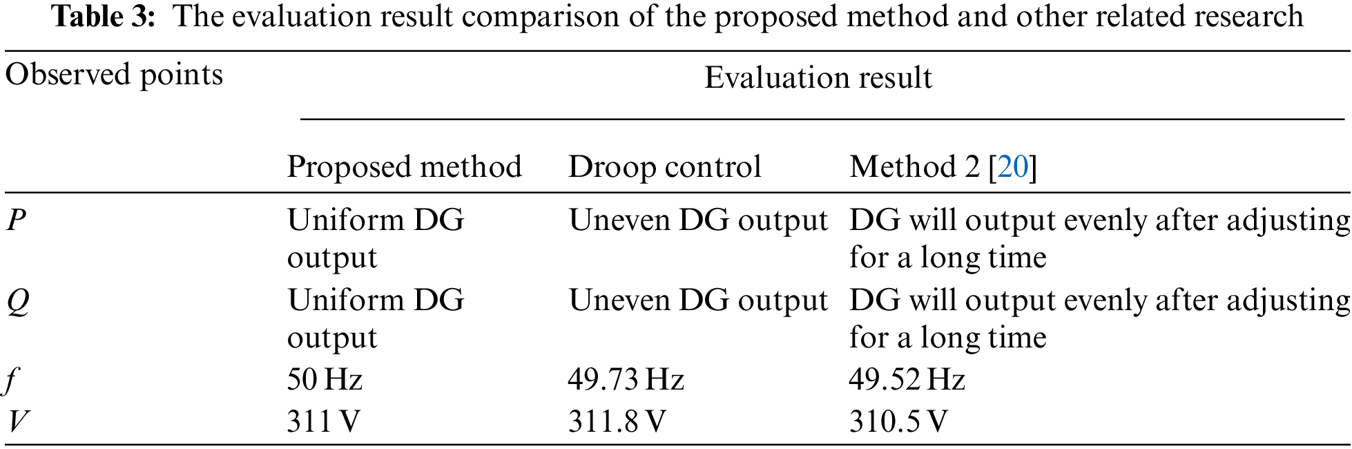
The results in Table 3 are the evaluation results of the four observation points. The evaluation results obtained in this paper are compared with the existing evaluation results [20]. Combined with each observation points power quality index values, the results obtained in this paper are reliable.
It is worth emphasizing that, different from the existing control methods, the simulation process of the distributed layered control strategy proposed in this paper is shown in Sections 4.1, 4.2, and 4.3, which can not only achieve the control objectives of power, voltage, and frequency but also adopt distributed algorithms in each layer of the layered control. There is no need for the centralized control center to analyze and calculate the parameters and transmit them to each controller. The decentralized method is adopted to control the microgrid as a whole, achieving the control goal and increasing the flexibility of the microgrid.
In this paper, based on the hierarchical control framework of traditional microgrid, the MA-FTCA is applied to the control strategy of each layer of the hierarchical control so that the control of active and reactive power, frequency, and voltage of the microgrid, as well as the cooperative control between each DG. Only a small amount of communication and information exchange can achieve global control, no need for a centralized control center, saving the investment of communication equipment and lines, and making the control of microgrid more flexible and reliable. The main novelties/achievements of this paper can be summarized as follows:
(1) The frequency voltage compensation is applied to ensure that the frequency and voltage of the system are stable at the rated value.
(2) When the load side of the islanded MG system changes, active power and reactive power output changes can be distributed among the power sources according to the proportion of their spare capacity by using multi-agent technology.
(3) Using the MA-FTCA, the convergence time of active spare capacity is nearly 50% shorter than that of the general consistency protocol. Therefore, the algorithm in this paper is easier to converge to the optimal solution of higher quality at a faster speed.
Future research will focus on the following aspects:
(1) This paper mainly uses layered structure and multi-agent theory to optimize the control of microgrids. In the actual situation, a microgrid is affected by communication network delay, packet loss, failure, and other factors. The control and fault-tolerant mechanism of microgrid under communication delay still need further research.
(2) In the simulation verification part, the random variables of the system are added to verify the feasibility and superiority of the proposed strategy.
In the traditional power system, each control device has communication, which provides the hardware foundation for the actual implementation of this paper. On this basis, the dispatchable DG is regarded as an agent by using the multi-agent theory. Agents can exchange partial information through distributed communication to achieve system-level functions. The communication between DG is decentralized, which reduces the requirement of communication bandwidth and dramatically improves the robustness and reliability of the system. In addition, in the hierarchical structure of the microgrid, each layer adopts multi-agent technology to achieve the desired goal. Therefore, distributed control based on multi-agent can be applied to large-scale systems.
Funding Statement: The authors gratefully acknowledge the financial support provided by Opening Foundation of Key Laboratory of Opto-technology and Intelligent Control (Lanzhou Jiaotong University), Ministry of Education (KFKT2020-11).
Conflicts of Interest: The authors declare that they have no conflicts of interest to report regarding the present study.
References
1. Ai, Q., Liu, S. Y., Wu, R. B. (2016). Research status and prospect analysis of multi-agent system in energy internet system. High Voltage Technology, 42(9), 2697–2706. DOI 10.13336/j.1003-6520.hve.20160907002. [Google Scholar] [CrossRef]
2. Ahmethodzic, L., Music, M. (2021). Comprehensive review of trends in microgrid control. Renewable Energy Focus, 38, 84–96. DOI 10.1016/j.ref.2021.07.003. [Google Scholar] [CrossRef]
3. Mathew, P., Madichetty, S., Mishra, S. (2019). A multilevel distributed hybrid control scheme for islanded dc microgrids. IEEE Systems Journal, 13(4), 1–8. DOI 10.1109/JSYST.2019.2896927. [Google Scholar] [CrossRef]
4. Zhang, M. R., Wang, J. Y., Song, B. H., Wei, L. (2019). Study on stable operation and mode smooth transition of microgrid. Power System Protection and Control, 47(20), 7–15. DOI 10.19783/j.cnki.pspc.181346. [Google Scholar] [CrossRef]
5. Guo, Q., Lin, L. Y., Wu, H. Y. (2015). An improved droop control strategy for precise distribution of reactive power in distributed power supply. Automation of Electric Power Systems, l39(15), 30–34+74. DOI 10.7500/AEPS20151206001. [Google Scholar] [CrossRef]
6. Chen, X. Q., Jia, H. J., Chen, S. Y. (2017). Improved droop control strategy based on line impedance identification for micro-grid reactive power sharing in micro-grid equalization. High Voltage Engineering, 39(15), 1271–1279. DOI 10.13336/j.1003-6520.hve.20170328026. [Google Scholar] [CrossRef]
7. Shahen, A. M., Elsayed, A. M., Ginidi, A. R., Elattar, E. E., Ei-sehiemy, R. A. (2021). Effective automation of distribution systems with joint integration of DGs/SVCs considering reconfiguration capability by jellyfish search algorithm. IEEE Access, 9, 92053–92069. DOI 10.1109/ACCESS.2021.3092337. [Google Scholar] [CrossRef]
8. Shahen, A. M., Elsayed, A. M., Ei-sehiemy, R. A., Ginidi, A. R., Elattar, E. E. (2021). Optimal management of static volt-ampere-reactive devices and distributed generations with reconfiguration capability in active distribution networks. International Transaction on Electrical Energy System, 31(11), 13126. DOI 10.1002/2050-7038.13126. [Google Scholar] [CrossRef]
9. Kulkarni, S. V., Gaonkar, D. N. (2021). Improved droop control strategy for parallel connected power electronic converter based distributed generation sources in an islanded microgrid. Electric Power Systems Research, 201(3), 107531. DOI 10.1016/j.epsr.2021.107531. [Google Scholar] [CrossRef]
10. Kulkarni, S. V., Gaonkar, D. N., Guerrero, J. M. (2021). Operation of the microgrid with improved droop control strategy and an effective islanding detection technique for automatic mode switching. Electric Power Components and Systems, 49(4–5), 517–531. DOI 10.1080/15325008.2021.1970289. [Google Scholar] [CrossRef]
11. Mi, Y., Wu, Y. W. (2017). Coordinated control of autonomous DC micro-grid with dynamic load power sharing. Power System Technology, 41(2), 440–447. DOI 10.13335/j.1000-3673.pst.2016.1049. [Google Scholar] [CrossRef]
12. Taher, A., Taha, A., Hasanien, H. (2021). Decentralized control based on hybrid water cycle and moth-flame optimization of fractional-order fuzzy PID in a multiple DGs faulty autonomous microgrid. International Journal on Energy Conversion, 9(5), 239–250. DOI 10.15866/irecon.v9i5.20291. [Google Scholar] [CrossRef]
13. Li, Z. W., Zang, C. Z., Zeng, P. (2018). Fully distributed hierarchical control of parallel grid-supporting inverters in islanded AC microgrids. IEEE Transactions on Industrial Informatics, 14(2), 679–690. DOI 10.1109/TII.2017.2749424. [Google Scholar] [CrossRef]
14. Rosero, C. X., Velasco, M., Martí, P. (2020). Active power sharing and frequency regulation in droop-free control for islanded microgrids under electrical and communication failures. IEEE Transactions on Industrial Electronics, 67(8), 6461–6472. DOI 10.1109/TIE.2019.2939959. [Google Scholar] [CrossRef]
15. Li, J., Su, J., Yong, S. (2015). Microgrid secondary frequency control method based on life optimization of energy storage units. 2014 International Power Electronics and Application Conference and Exposition, pp. 1143--1147. Shanghai, China. DOI 10.1109/PEAC.2014.7038021. [Google Scholar] [CrossRef]
16. Wu, Y., Wu, Y., Guerrero, J. M. (2019). AC microgrid small-signal modeling: Hierarchical control structure challenges and solutions. IEEE Electrification Magazine, 7(4), 81–88. DOI 10.1109/MELE.2019.2943980. [Google Scholar] [CrossRef]
17. Taher, A. M., Hasanien, H. M., Ginidi, A. R. (2021). Hierarchical model predictive control for performance enhancement of autonomous microgrids. Ain Shams Engineering Journal, 12(9), 1867–1881. DOI 10.1016/j.asej.2020.12.007. [Google Scholar] [CrossRef]
18. Xin, H., Zhao, R., Zhang, L. (2015). A decentralized hierarchical control structure and self-optimizing control strategy for FP type DGs in islanded microgrids. IEEE Transactions on Smart Grid, 7(1), 3–5. DOI 10.1109/TSG.2015.2473096. [Google Scholar] [CrossRef]
19. Hang, Y., Zhang, K., Li, H. (2018). MAS-Based distributed coordinated control and optimization in microgrid and microgrid clusters: A comprehensive overview. IEEE Transactions on Power Electronics, 33(8), 6488–6508. DOI 10.1109/TPEL.2017.2761438. [Google Scholar] [CrossRef]
20. Zhou, Y., Wang, K. Y., Li, G. J. (2017). Distributed hierarchical control strategy for microgrid based on multi-agent consistency algorithm. Automation of Electric Power Systems, 41(11), 142–149. DOI 10.7500/AEPS20160920004. [Google Scholar] [CrossRef]
21. Liu, J. Y., Li, J. Q., Song, H. H. (2020). Nonlinear secondary voltage control of islanded microgrid via distributed consistency. IEEE Transactions on Energy Conversion, 35(4), 1964–1972. DOI 10.1109/TEC.2020.2998897. [Google Scholar] [CrossRef]
22. Su, C., Wu, Z. J., Dou, X. B. (2021). A distributed P-V coordinated control strategy for isolated microgrid. Electric Power Automation Equipment, 41(4), 101–108. DOI 10.16081/j.epae.202102034. [Google Scholar] [CrossRef]
23. Yu, Z. W., Ai, Q., Xiong, W. (2017). Hierarchical distribution real-time optimization strategy for microgrid based on multi-agent consistency protocol. Automation of Electric Power Systems, 41(18), 25–31+88. DOI 10.7500/AEPS20170105009. [Google Scholar] [CrossRef]
24. Ma, X. P., Yang, P. L., Dong, H. Y. (2017). Secondary control strategy of islanded micro-grid based on multi-agent consistency. 2017 IEEE Conference on Energy Internet and Energy System Integration (EI2), pp. 1–6. Beijing, China. DOI 10.1109/EI2.2017.8245599. [Google Scholar] [CrossRef]
25. Wang, F., Chen, X., He, Y. (2014). Finite-time consistent control of second-order multi-agent systems with joint connectivity. Control Theory & Applications, 2014(7), 981–986. DOI 10.7641/CTA.2014.40083. [Google Scholar] [CrossRef]
26. Wei, W. J., Ma, Y. Q., Li, Z. G. (2019). Cooperative output regulation of heterogeneous multi-agent system in finite time. Control Theory & Applications, 36(6), 885–892. DOI 10.7641/CTA.2018.80225. [Google Scholar] [CrossRef]
27. Liu, Z. J., Jin, L. X., Chen, Z. Y. (2019). Power control strategy of micro-grid based on intelligent consistency algorithm. Power Electronics, 53(5), 39–41. [Google Scholar]
 | This work is licensed under a Creative Commons Attribution 4.0 International License, which permits unrestricted use, distribution, and reproduction in any medium, provided the original work is properly cited. |