| Energy Engineering |
DOI: 10.32604/ee.2022.022069
ARTICLE
Production of Producer Gas from Densified Agricultural Biomass in Downdraft Gasifier and Its Application to Small Diesel Engines
1School of Renewable Energy, Maejo University, Chiang Mai, 50290, Thailand
2Department of Mechanical Engineering, Faculty of Engineering, Chiang Mai University, Chiang Mai, 50200, Thailand
*Corresponding Author: Kittikorn Sasujit. Email: k.sasujit@yahoo.com
Received: 19 February 2022; Accepted: 31 May 2022
Abstract: Biomass is becoming one of the most popular renewable energy sources, especially from agricultural wastes. These wastes can be gasified and utilized in various industries. This experimental study investigated producer gas generation from densified agricultural fuels such as corncobs, rice husks, wood chips, and oil palm fronds in a 50 kWth throatless downdraft gasifier. This system produced combustible gases such as H2, CO, and CH4, which were utilized as a substitute for diesel fuel in a small diesel engine for power generation. The results showed that the gasifier performs successfully and seems to prefer pellets to briquettes. Producer gas contains 18%–20% carbon monoxide, 1%–6% hydrogen, and 0.9%–1.9% methane. Maximum gasification efficiencies of 53%–71% were achieved with biomass pellets from wood chips, corncobs, oil palm fronds, and rice husks, with producer gas calorific value of 2.94–3.85 MJ/Nm3. The average fuel consumption rate was between 6.72–14.43 kg/h, while the producer gas yield was between 2–3 Nm3/kg. The average gravimetric concentration of biomass tar in the raw product gas was found to be in the range of 23–50 g/Nm3, in which pelletized fuel appeared to show slightly lower tar than briquette fuel. The tar was primarily composed of five compounds: Benzo (a) pyrene, chrysene, pyrene, phenanthrene, 1-methylnaphthalene, and several other polycyclic aromatic compounds. The producer gas from oil palm frond briquettes and biodiesel were tested in a gas engine system in a dual fuel mode. A thermal efficiency of 22.21% was achieved with 2500 W electric load and a 72% biodiesel displacement rate, respectively.
Keywords: Agricultural residues; biomass; densification; gasification; tar removal
Nomenclature
| BSFC | Brake specific fuel consumption (kg/kWh) |
| BSEC | Brake specific energy consumption (MJ/kWh) |
| BTE | Brake thermal efficiency (%) |
| Ct | Tar concentration of producer gas (g/Nm3) |
| GC-FID | Gas chromatography-flame ionization detector |
| GC-TCD | Gas chromatography-thermal conductivity detector |
| Hg | Lower heating value of producer gas (kJ/Nm3) |
| Hs | Heating value of biomass (kJ/kg) |
| LHVρg | Low heating value of producer gas (MJ/Nm3) |
| LHVbio | Low heating value of biodiesel (MJ/kg) |
| Ms | Biomass consumption (kg/s) |
| mf | Mass flow rate of biomass (kg/h) |
| N | Engine speed of small diesel engine (rpm) |
| P | Brake power (kW) |
| PAH | Polycyclic aromatic hydrocarbon |
| Qg | Producer gas flow rate (Nm3/h) |
| Vg | Volume of sample producer gas (Nm3) |
| Vρg | Producer gas flow rate (m3/s) |
| Wc | Biomass feed rate (kg/h) |
| Wt | Weight of total tar in tar sampling (g) |
| Yg | Producer gas yields (Nm3/kg) |
| ηth | Cold gas efficiency (%) |
| τ | Small engine torque (Nm) |
Energy consumption in Thailand has increased in recent years in relation with economic growth. The Royal Thai Government announced that should increase alternative energy from 12% to 30% by 2036 [1]. Thailand, with its abundant and diverse biomass and agricultural wastes, should have a great opportunity for renewable energy production. Biomass is significant as a sustainable energy source. It can be converted to more valuable sources of energy through a variety of processes, including thermal, biological, mechanical, and physical. On the other hand, biomass sources are limited and rapidly depleted if grossly mistreated. As a result, it is critical to manage these resources effectively and prudently [2]. Densification is a pre-treatment method of the raw biomass for conversion into useful energy via biomass conversion technology [3]. Moreover, the conversion of biomass to high-density solid fuels may solve the problem of agricultural waste and high reliance on wood as a fuel source [4–7].
Densification technology can be carried out at room temperature and biomass preheating before densification enhances physico-mechanical properties such as thermal and combustion properties [8–11]. The solid fuel treatment by using thermal is recommended to improve combustion qualities, especially when the fuel is used for industrial purposes [12]. Moreover, optimal fuel durability requires a densification pressure greater than 38 MPa and moisture content of around 8%–10% [13].
Gasification of biomass has also proven to be a highly efficient method of utilizing biomass for a variety of different uses in processes that produce one or more valuable outputs and therefore is applicable to small and medium systems. Recent years have seen an increase in interest in the gasification technology platform because to its combination of flexibility and efficiency in biomass conversion. Many researchers’ studies on the gasification of agricultural residue briquettes in down-draft gasifiers are now being conducted. A gasification study was conducted on briquettes with a diameter of 25, 35, and 55 mm, derived from sugarcane bagasse, cotton stalk, and ground nutshell. It was found the average fuel consumption rate for various trials utilizing crop residue briquettes varied from 147.6–157.4 kg/h, with gasifier efficiency varying from 61%–69% [14]. The gasification of oil palm and tung tree briquettes was investigated using a downdraft gasifier and various fuel equivalence ratios ranging from 0.29 to 0.38. Maximum gasification efficiency was reported to be 76.24% and 70.15%, with producer gas yields of 4.46 and 3.72 Nm3/kg, respectively, and lower heating values of 3.20–3.23 MJ/Nm3 for oil palm wastes and tung tree briquettes [15]. Additionally, in a fixed bed tubular reactor, gasification of empty fruit branches from oil palm briquettes was examined. Increasing gasification temperature raised the heating value of the producer gas from 6.18–7.64 MJ/Nm3 and the cold gas efficiency from 35.19%–43.50% [16]. In practice, most of the biomass fuel will be utilized in industrial processes with direct combustion and gasification processes. The gasification process will be utilized to generate producer gas for electricity production, and the cold gas efficiency was around 60%–70%, and the calorific value of producer gas about 4–6 MJ/Nm3 [17]. Moreover, the performance of gas engines used to generate power was evaluated by using producer gas from gasification. The cold gas efficiency obtained from the gasification of municipal solid waste briquette fuel was around 65% with an engine load of 45 kW and the maximum thermal efficiency of a small diesel engine was 16% [18].
So far, there are a relatively small number of reports on gasification of agricultural residues. Works on comparison between pelletized and briquetted forms of agricultural residues, especially oil palm fronds, remain rare. Pellets have a very high density, which simplifies feeding and reduces the need for maintenance during operation [19]. In this study, comparison of different types of agro-densified biomass in the same gasifier in terms of typical gasification data for various fuel shapes, sizes, and densities; and different chemical compositions of pelletized and briquetted was of interest. The semi-continuous downdraft gasifier was applied to produce producer gas from densified agricultural biomass, including corncob, oil palm fronds, rice husk, and wood chip. The gasifier performance was evaluated in terms of the composition of the producer gas, the producer gas yield, cold gas efficiency, lower heating value, and tar content. Additionally, the performance of a small diesel gas engine system that generates electricity using oil palm frond briquette fuel was investigated. The engine performance was evaluated in terms of the biodiesel consumption rate, brake power, brake thermal efficiency and biodiesel displacement rate.
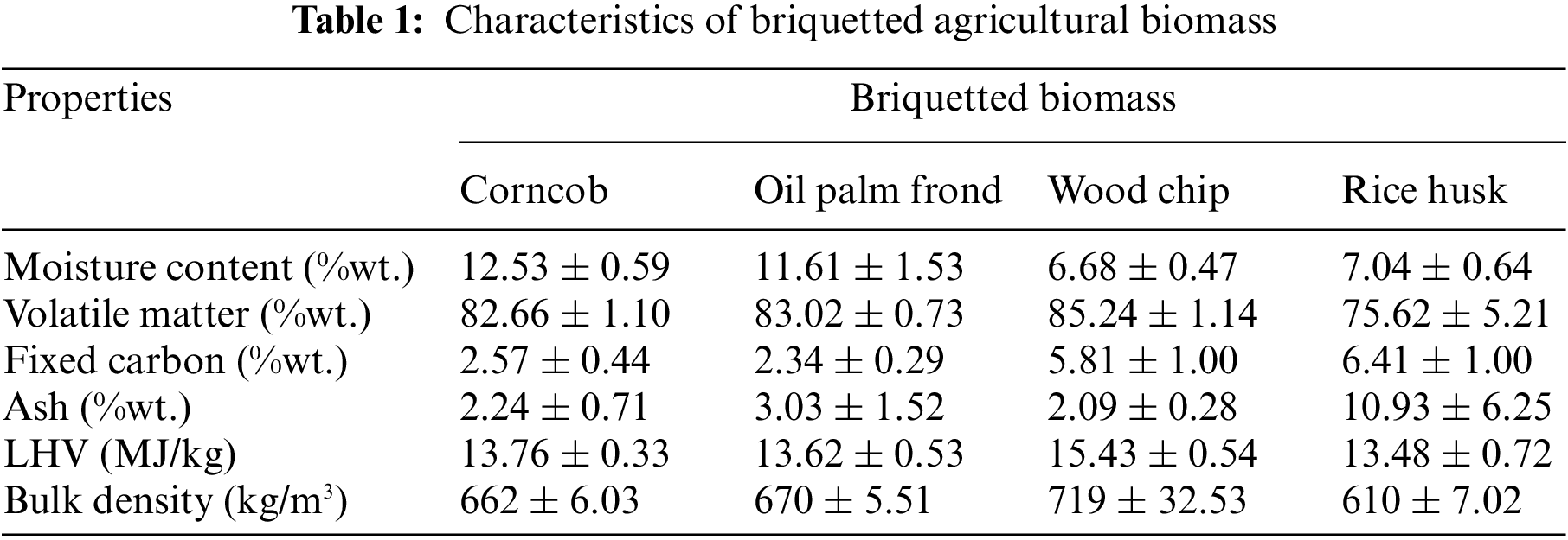
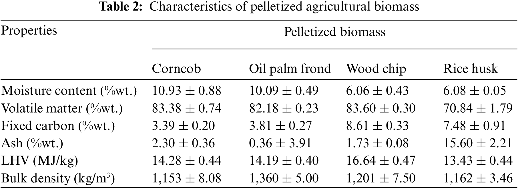
Biomass materials utilized in this investigation were corncobs, oil palm fronds, wood chips, and rice husks. They were chopped to an average thickness of 2–5 mm with a chopper machine and dried in the sun for about a week until their water content reached about 10%–12%. After that, they were densified using briquetting (20–35 mm long, diameter of 50–55 mm) and pelleting (20–30 mm long, diameter of 5–6 mm) machinery. The results of the proximate analysis and the calorific values of the densified biomass from this research are summarized in Tables 1 and 2.
2.2 Experimental Apparatus and Setup
2.2.1 Densification Process of Biomass
The pelleting machine was powered by a 5 hp, single-phase electric motor. The motor speed was reduced to about 30 rpm using a 1:60 speed reducer. Its overall dimensions are 700 mm in length, 400 mm in width, and 800 mm in height. Two roller dies, one grooved and one flat, allow the mixing and pressing of the pellet mixture in the pelleting chamber. The chamber frictional forces and temperature rise because of the increasing internal pressure. After that, pellets were sent to a 30° angled output duct after extrusion. The biomass pellets were 5–6 mm in diameter and 20–30 mm in length. In the case of the briquetting machine, it was a low-pressure briquetting machine of the screw-press type. The most significant components of an extruder were the barrel (which contains one or more screws) and the die. An extruder was a thermomechanical device that consists of many components, the most important of which were the barrel and the die. The temperature of these two sections was often controlled by a heating and cooling system. The biomass briquettes were then delivered to the exit pipe. Its dimensions were 50–55 mm in diameter and 20–35 mm in length, as shown in Tables 5 and 6.
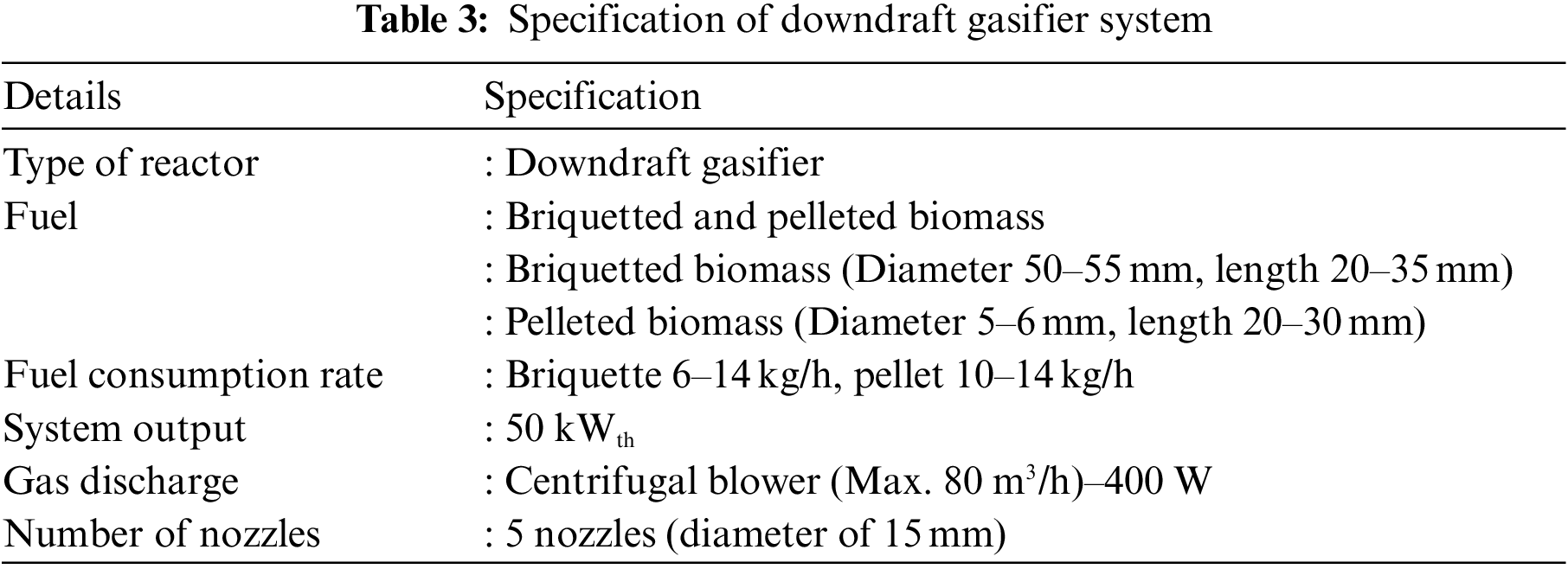
Fig. 1 presents the downdraft gasifier system used for the experiments. The gasifier used in this experiment was a 50 kWth fixed bed downdraft gasifier. The total height of reactor chamber of gasifier was about 1130 mm, with the throated diameter of 150 mm. For the biomass being supported on a grate at the bottom of the gasifier, water sealing was adopted to avoid product gas leakage. The gasifier operates via suction from a centrifugal blower (maximum 400 watts), which allows air to enter the reactor via five air nozzles monitored by an air flow meter. The characteristics of the biomass gasifier for this study shows in Table 3. In this study, an equal position of the six air nozzles was used in the experiments. The combustion zone is placed directly by the air intake. The gases are forced through a constriction to the reduction zone, where the gasification reactions take place.
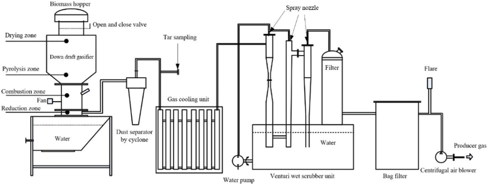
Figure 1: Schematic diagram of the downdraft biomass gasifier
Producer gas cleaning methods can be divided into three stages before being flared: cyclone, venturi wet scrubber, and filters. After cleaning, the gas is cooled to avoid overheating the blower and small diesel engine. Data analysis for the evaluation of downdraft gasification were calculated by Eqs. (1)–(3):
Producer gas yields (
where
Cold gas efficiency (
where
Lower heating value (
where
Downstream from the downdraft gasifier is the concentration measurement system. The schematic of the product gas sampling train depicting its various component parts is shown in Fig. 2. Collection of moisture and tar is performed in a series of six impinger bottles according to the tar protocol. The tar sampling unit was developed under isokinetic conditions using standard protocol-BSI DD CEB/TS 15439:2006 [22]. It was designed for the measurement of organic contaminants (tars). In the series of impinger bottles, the first impinger bottle consists of the blend of moisture and lighter tar that is collected from the product gas by absorption in isopropanol. The heat released by gas cooling and condensation is removed either in an external water bath or by an additional heat exchanger before the condenser. The heat exchanger may be necessary for high moisture producer gases and should be designed to meet the demands of the gasifier. The condenser is a standard impinger bottle with an internal liquid quench system for isopropanol, which is especially suitable for producer gases containing higher tar levels. After the moisture collector, the gas is passed through a series of 5 impingers with solvent and 1 final impinger which is empty. Gas samples are pumped through the sampling unit using a pump connected to a variable flow regulator that provides the possibility to adjust the gas flow rate in the range of 55–60 l/min. Once the tar collection is complete, the contents of all the bottles are collected, the tubing and glass parts are washed with isopropanol solution. The concentration of tar in producer gas produced from downdraft gasification was calculated by Eq. (4).
where
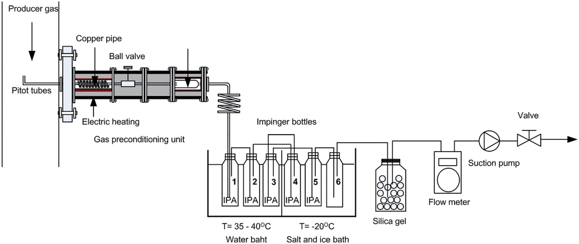
Figure 2: Schematic of biomass tar sampling
2.2.4 Small Diesel Engine Testing
The small diesel engine is evaluated with a dual fuel system consisting of biodiesel and producer gas. A dynamometer set was used to measure the engine torque, which was then presented on a display panel. There were 100 W lamps and 500 W heaters for performance tests. The consumption of biodiesel was determined using a specific gravity fuel flowrate on a weighing scale. The gasification of briquetted biomass derived from wood and oil palm fronds was examined in this study. The detailed specifications of the small diesel engine may be seen in Table 4, as well as the experimental setup, which is shown in Fig. 3.
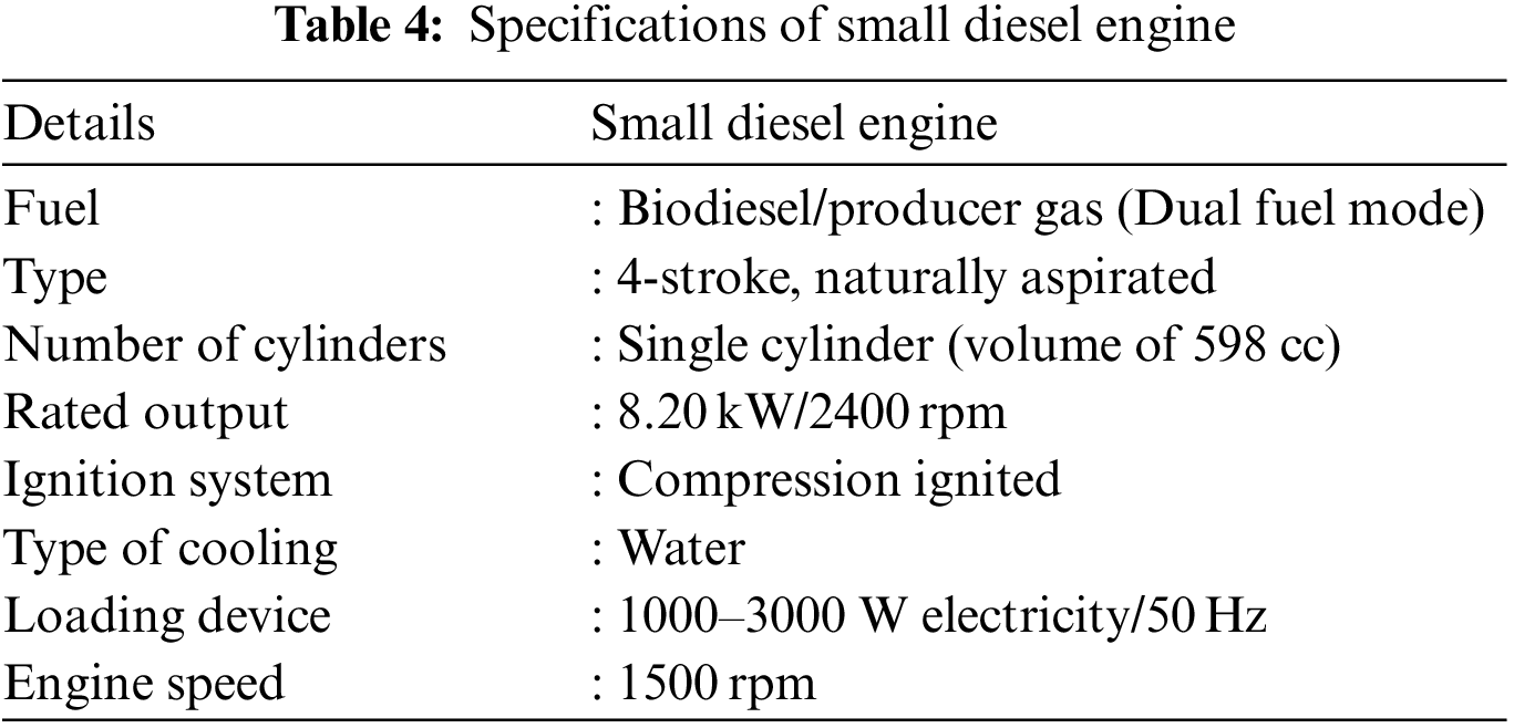
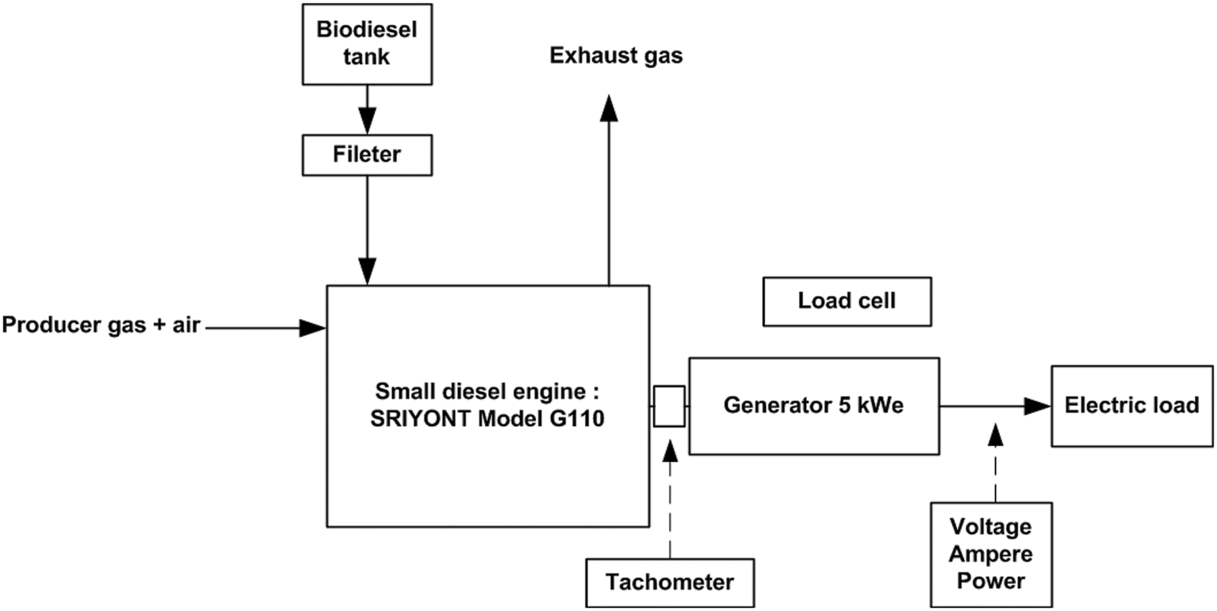
Figure 3: Schematic diagram of the small diesel engine setup
The experiments were conducted in the downdraft gasifier using densified agricultural residues in the form of briquettes (50–55 mm in diameter, 20–35 mm thick) and pellets (5–6 mm in diameter, 20–30 mm long) of corncobs, rice husks, wood chips, and oil palm frond. Biomass fuel was loaded into the reactor of 30–40 kg and the starting blower. The fuel bed was ignited by holding a flame, then the gas flowing through the starting burner began burning. The air was supplied into the combustion zone of the reactor by a 185 W vortex blower, which was controlled by a ball valve and monitored using an anemometer (Lutron: YK-80AM, Australia). The inlet air flow rate into the reactor was between 16–20 m3/h. Producer gas was collected after the gas cleaning process through a dry cyclone for dust removal, a cool water basin with a heat exchanger, a venturi scrubber system, and a filter tank. The product gas volume was measured using a gas flow meter. The producer gas composition was analyzed by a gas chromatograph (Model: GC-8A, Shimadzu, Japan) with a thermal conductivity detector (TCD), with helium as the carrier gas, in terms of H2, CO, CH4, N2, O2 and CO2. Tar content is measured at downstream from the gasifier according to the tar protocol method. Moreover, this experiment to evaluate a small diesel engine by using dual fuel from producer gas and biodiesel was carried out at different electric loads varying from 1000, 1500, 2000, 2500, and 3000 W with constant engine speed of 1500 rpm. The performance evaluation of the small diesel engine was calculated by Eqs. (5)–(10).
Brake power (BP) [23]:
Brake specific fuel consumption (BSFC) [23]:
where
Brake thermal efficiency (BTE) [18,23]:
Brake specific energy consumption (BSEC) [23]:
where
The biomass gasifier system was evaluated in terms of its producer gas composition, calorific value, producer gas yield, producer gas component, and cold gas efficiency in this study. Additionally, the performance of a small diesel internal combustion on dual fuel (biodiesel and producing gas) was evaluated.
The purpose of this study was to investigate densified biomass for producer gas production. The mass flow rate of air used in the gasification reaction was 18.35 ± 2.68 kg/h. The biomass was fed semi-continuously for about 5–6 h, depending on the type of biomass. An average fuel consumption rate of biomass briquettes was found to be between 6.72–14.43 kg/h, while biomass pellets consumed between 9.73–13.86 kg/h, as shown in Tables 5 and 6. The results indicated that the fuel consumption rates for densified biomass from corncob, rice husk, and wood chip were slightly different. In addition, pellet fuel made from densified oil palm fronds was consumed more than briquetted fuel. According to Dzombo et al. [17], the size of the feedstock was discovered to influence the combustion reaction inside the reactor. It was discovered that densified briquette biomass deforms during the reaction, restricting airflow and thereby limiting gasification. Moreover, the pellet fuel demonstrated good combustion responses due to the homogeneous size of the feedstock and can be continuously fed biomass, as shown in Fig. 4.
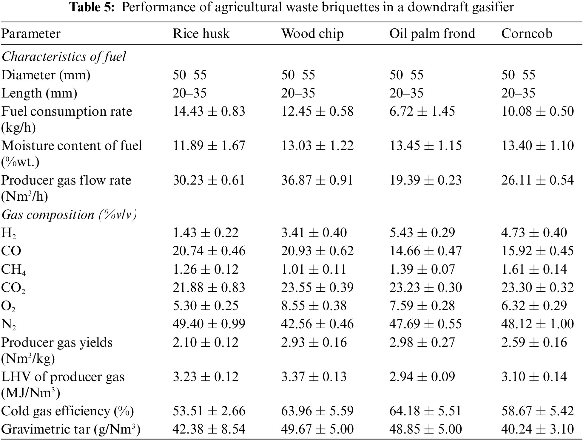
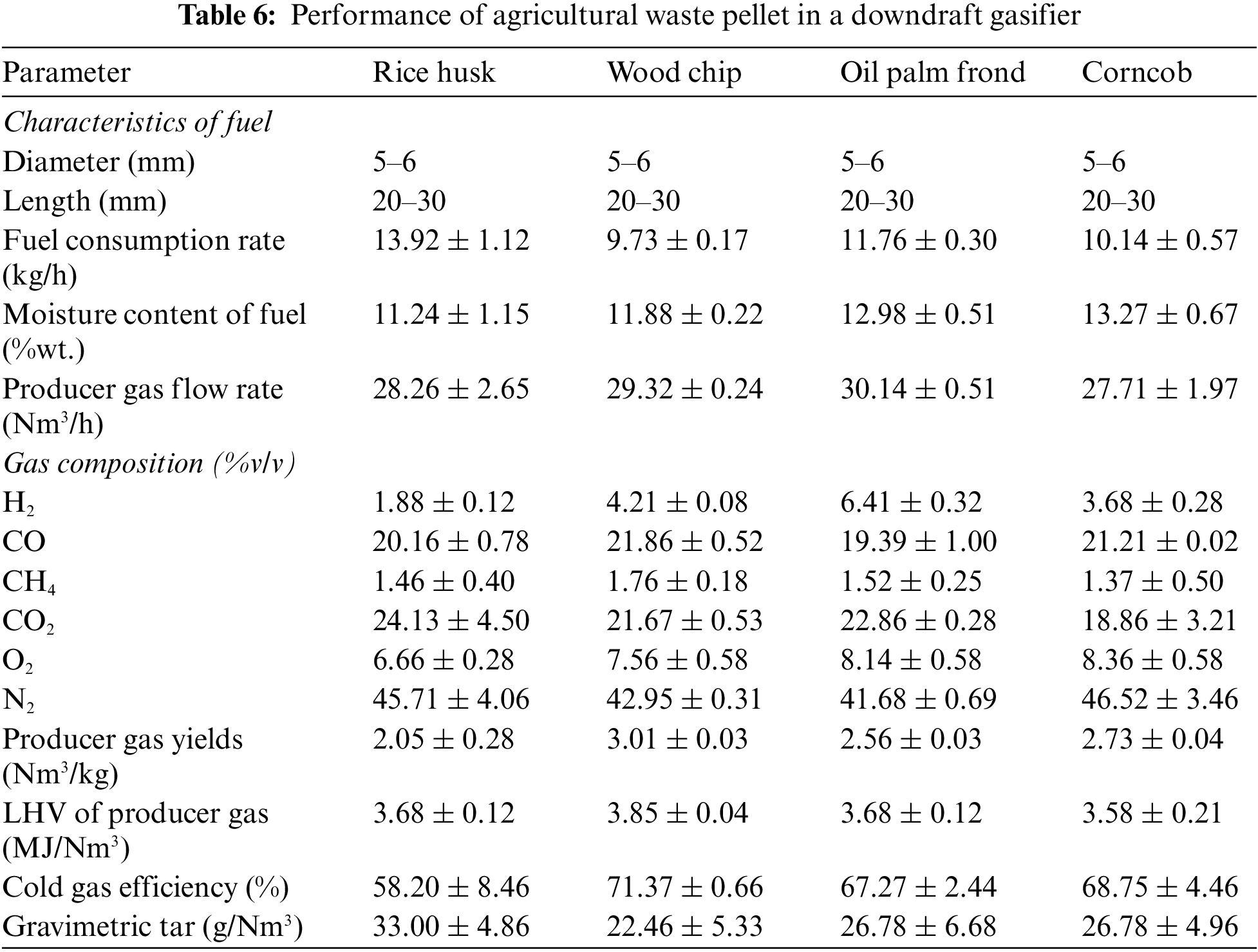
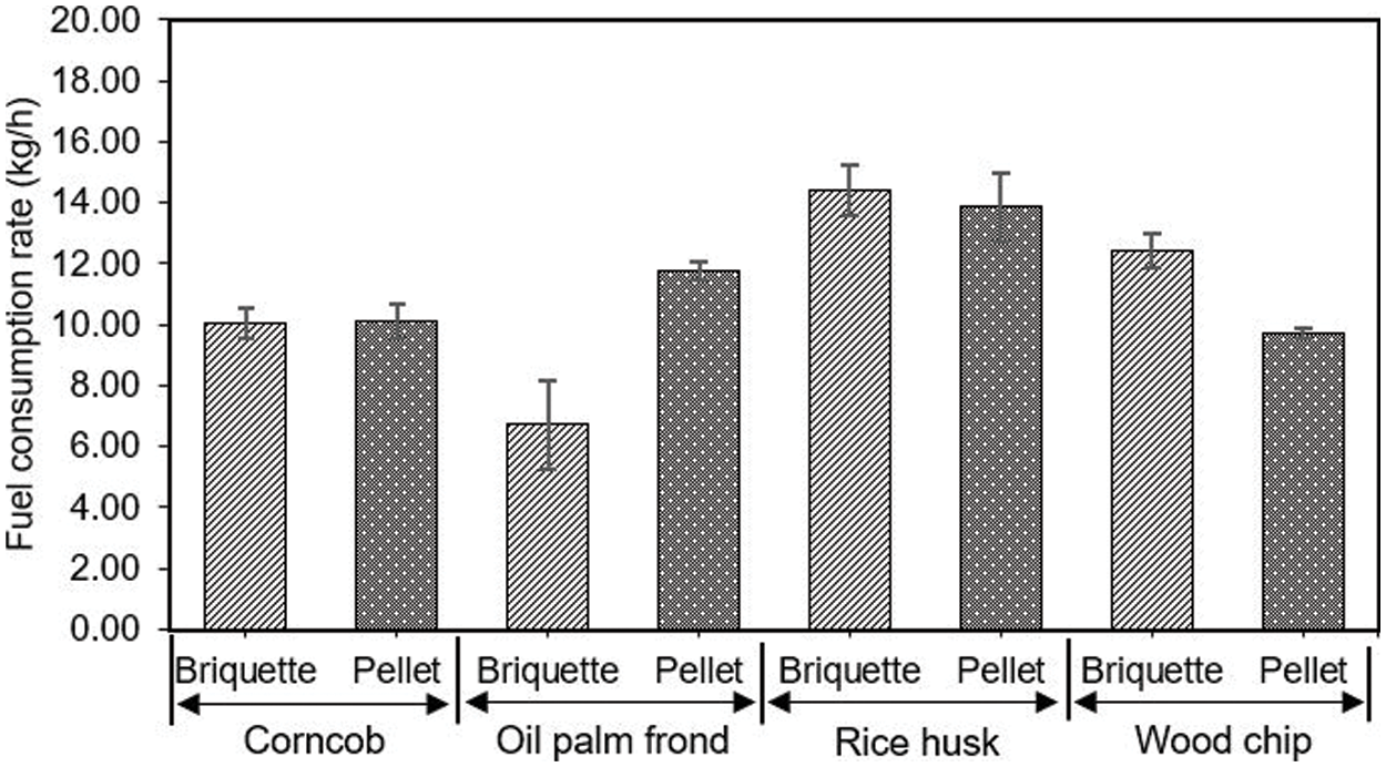
Figure 4: Fuel consumption rate in gasification with briquettes and pellet
3.2 Temperature Profile of the Gasification Process
The temperature profile of the gasification process was obtained from three thermocouples of type K inside the gasifier and 1 thermocouple of type R in the combustion zone. Temperature parameters were measured at 5-min intervals to record the stages of thermochemical conversion: the drying zone, pyrolysis zone, combustion zone, and reduction zone, as shown in Fig. 5. First, charcoal was used to ignite the gasifier, and then densified fuel were loaded in the reactor. This process took around 20–25 min. Results are plotted, showing average of 3 experimental observations. In these tests, wood pellets were utilized. It was found that the temperature varied between 30°C–50°C at the drying zone, 89°C–500°C at the pyrolysis zone, 100°C–1100°C at the combustion zone, and 100°C–780°C at the reduction zone for wood pellets. After 40 min of gasification, the combustion zone temperature exceeded 800°C. Thus, the findings of this study showed the thermal behavior of the gasifier in accordance with the temperature profile of the gasification reaction. The literature shows that the temperature of the combustion zone varies between 800°C–1100°C; the reduction zone was around 400°C–500°C for wood chip fuel in downdraft gasifier [24], which confirms the establishment of gasification.
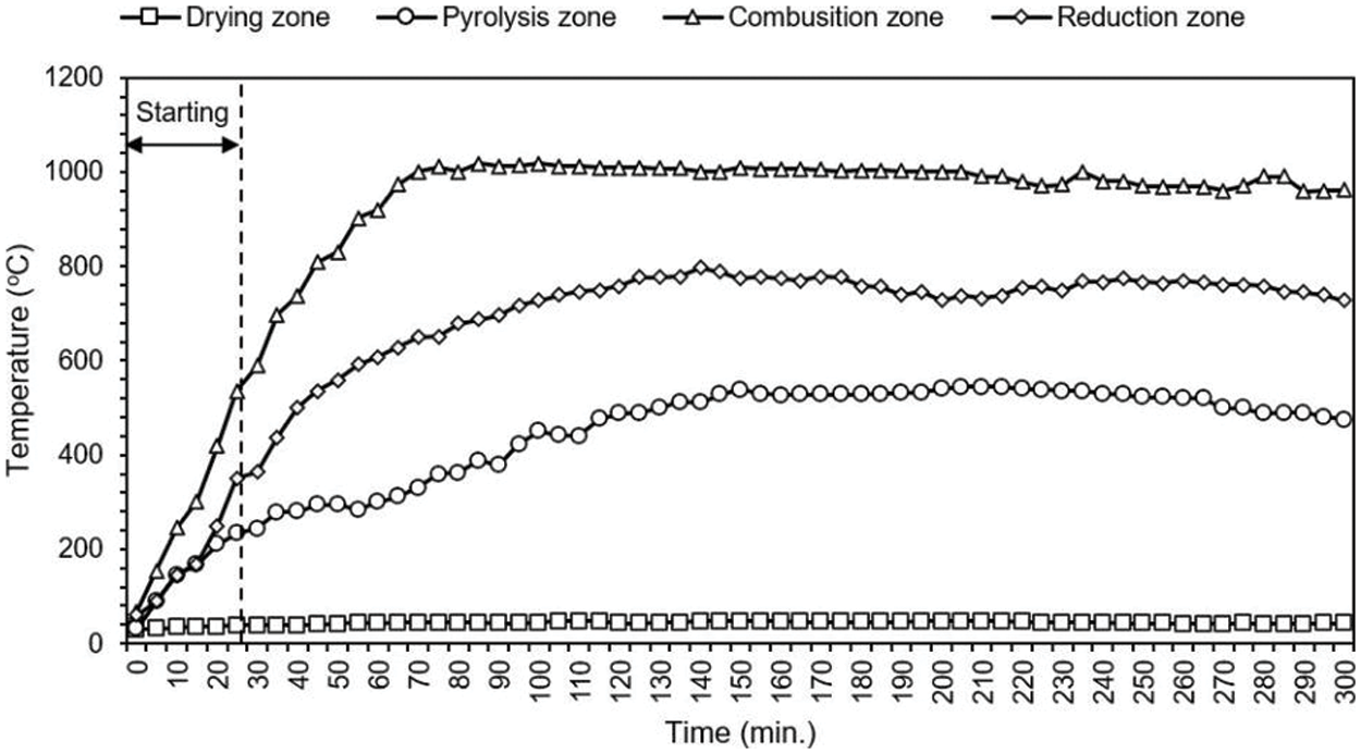
Figure 5: Temperature profile inside the gasifier by using wood pelletized as fuel
3.3 Yields and Lower Heating Value of Producer Gas
Fig. 6 shows the low heating value of producer gas was calculated using the composition of the producer gas. Carbon monoxide, hydrogen and methane were the main components of the producer gas, resulting in the lower heating value in a narrow range of 2.94–3.85 MJ/m3, reaching a maximum of 3.85 MJ/m3 from wood chip pellet. The increasing and decreasing trends in producer gas heating value variation corresponded to changes in carbon monoxide and hydrogen content variation by volume [25]. The production of producer gas from agricultural densification in this study was determined to be within a narrow range of 2.05–3.00 Nm3/kg. The wood chip pellet with the highest heating value of product gas and producer gas yields was used as a fuel in gasification. According to literature, biomass gasification using oil palm waste was 2.51 Nm3/kg [20], as illustrated in Fig. 7.
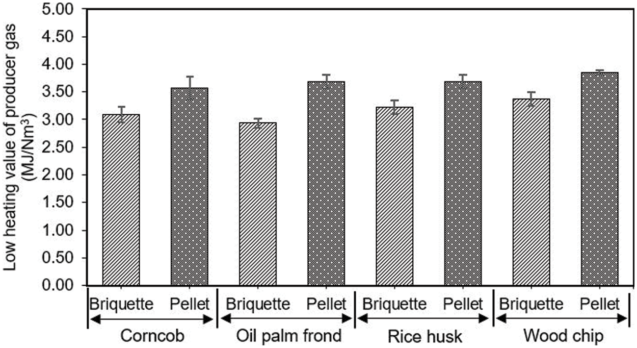
Figure 6: Low heating value from biomass gasification with briquettes and pellet
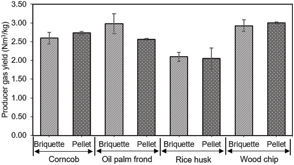
Figure 7: Producer gas yield from gasification with briquette and pellet biomass
Fig. 8 shows the cold gas efficiency were in the range of 53.51%–64.18% and 58.20%–71.37% for the briquetted and pelletized fuels. The maximum cold gas efficiency was 71.37% for pelletized wood chip fuel. However, a clear difference can be observed in the gas composition of wood pellets. The gas composition from wood pellets is richer in H2 and CO than for other fuels. It shows the maximum producer gas yield was 3.01 Nm3/kg and a low tar content from gasification. According to the report, the cold gas efficiency was in a comparable range of 72%–76% for oil palm frond wastes and 66%–70% for tung tree wastes [15]. Further, it was also comparable to the downdraft gasifier efficiency of 62% using charcoal in the gasification for ceramic firing process [26], the range of 62%–69% using agricultural waste [27], and an average of 65% using briquette fuel from municipal solid waste [18].
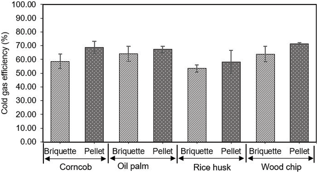
Figure 8: Cold gas efficiency from gasification with briquette and pellet biomass
3.5 Tar Concentration in Product Gas
Fig. 9 shows the tar concentration in densified agricultural wastes fuel. The biomass tar generated during gasification included a diverse range of hydrocarbon compounds, acids, alcohols, aldehydes, ketones, esters, heterocyclic derivatives, and phenolic compounds [28]. The results of this investigation observed that the mean concentration of tar in briquettes was between 33–45 g/Nm3, while that in pellets was between 17–28 g/Nm3. These values were greater than those reported in the literature for a lower tar content (less than 100 mg/Nm3) from a downdraft gasification system [29]. From the results, it was found that the tar content from gasification showed high content because of the low reaction temperature inside the gasifier and the low retention time for tar cracking. However, this experiment used an induced-draft force fan for air inlet into the reactor, which resulted in a low air flow rate into the combustion zone and a low temperature in this zone. However, the forced-draft fans show higher reaction temperatures than the induced-draft force fans when gasification is done with the fan. According to the result, the average temperatures in the combustion and reduction zones were lower at 1000°C and 800°C when compared to the typical combustion zone temperature of 1100°C–1500°C and the reduction zone temperature of 500°C–900°C of gasification.
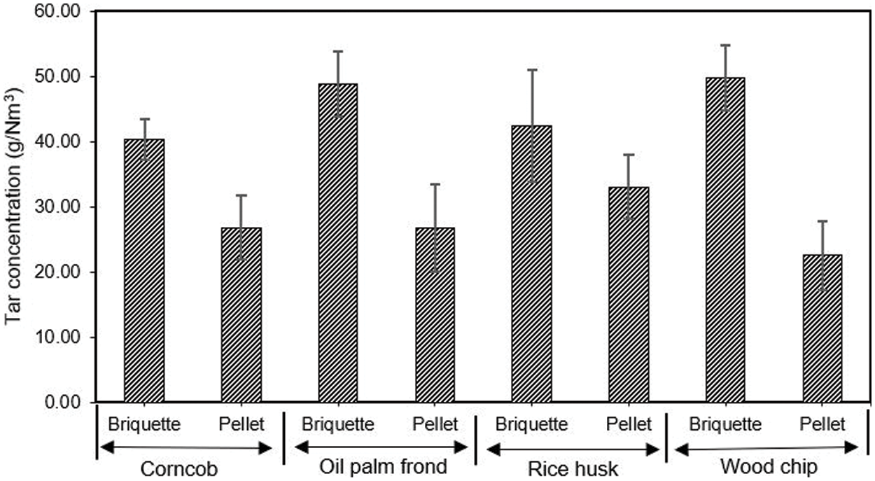
Figure 9: Gravimetric tar content from biomass gasification
Thus, the producer gas from downdraft gasifiers still requires cleaning to remove biomass tar before being used in internal combustion engines to generate electricity. Gas chromatography (GC-FID) analysis indicated that the chemical compounds in the tar from gasification were comparable with the EPA8310 PAH standard (PAH Mixture-18 components, RESTEK, USA). It was found that five polycyclic aromatic compounds consist of Benzo(a) pyrene (C20H12), Chrysene (C18H12), Pyrene (C16H10), Phenanthrene (C14H10), 1-Methylnaphthalene (C11H10) and several other polycyclic aromatic compound, as shown in Fig. 10. Results of this study according to the tar compound in gasification using empty fruit bunch showed six polycyclic aromatic compounds consist of naphthalene, acenaphthylene, phenanthrene, anthracene, fluoranthene, and pyrene [30].
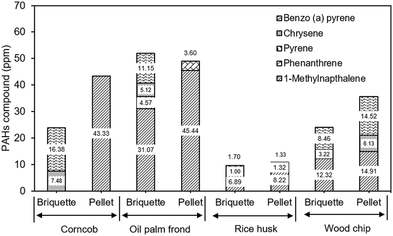
Figure 10: PAHs compound in biomass tar content from biomass gasification
3.6 Evaluating Engine Performances in a Dual Fuel
The purpose of this study was to determine the performance of a small diesel engine using dual fuel (biodiesel and producer gas). The specific fuel consumption rate, brake power, brake thermal efficiency, and biodiesel displacement rate of the engine were all determined experimentally. Oil palm fronds were used for producer gas production in the gasification system of this study.
3.6.1 Specific Fuel Consumption Rate of Biodiesel and Densified Fuel
Fig. 11 shows the effect of an electric load in the range of 1000–3000 W, the specific biodiesel consumption for dual fuel in engine. The specific fuel consumption tended to decrease with increasing electric load because of the effect of increasing brake power of engine. Additionally, biodiesel has a higher specific fuel consumption rate than the dual fuel of biodiesel and oil palm frond densified fuel. For dual fuel (biodiesel and producer gas), the minimum specific fuel consumption was 0.262 and 0.125 kg/kWh. Fig. 12 shows the specific biomass consumption rate by varying electric load. It was found that biomass fuel consumption tended to decrease with increasing electric load. The minimum biomass consumption was 0.734 kg/kWh with an electric load of 3000 W.
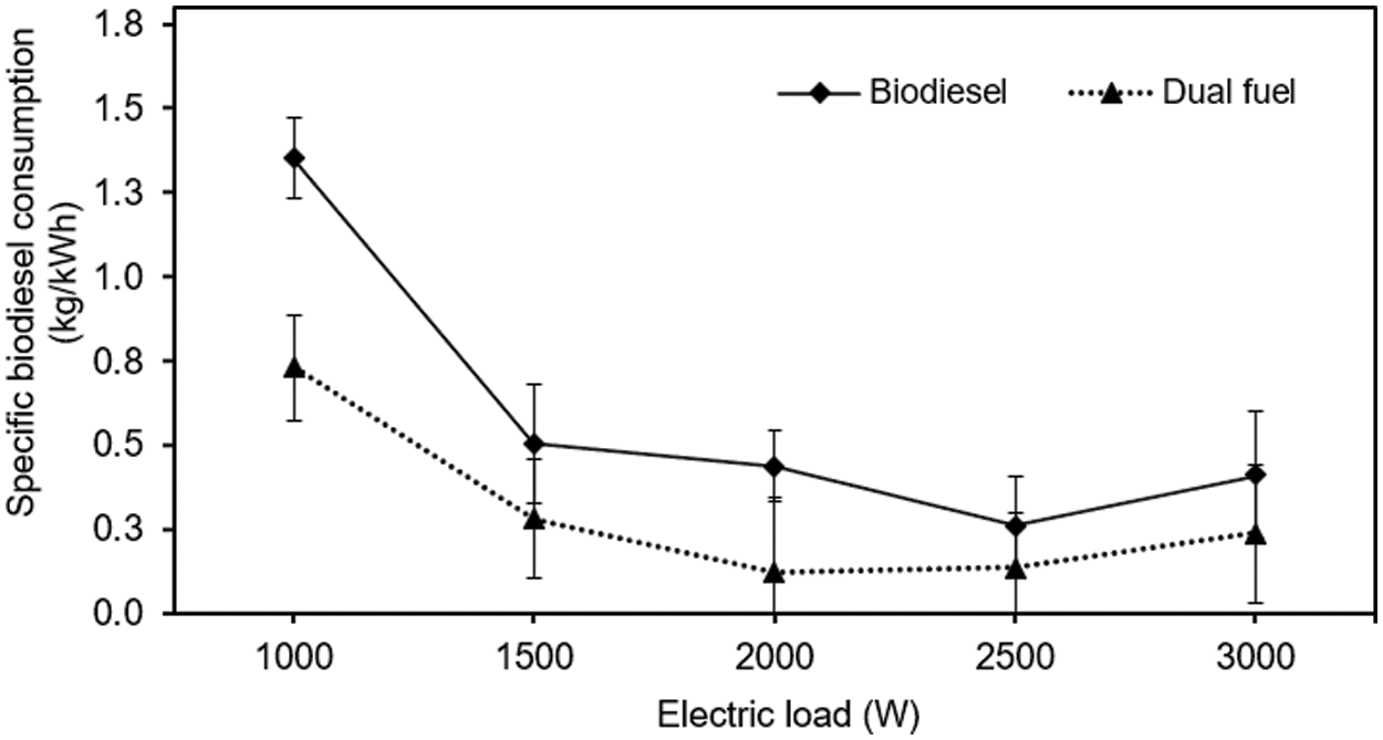
Figure 11: Specific biodiesel consumption of small diesel engine
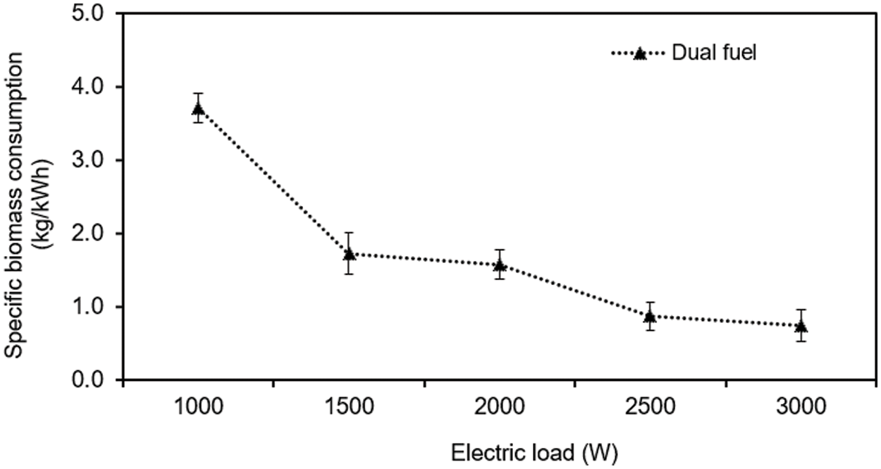
Figure 12: Specific biomass consumption of small diesel engine
3.6.2 Brake Power and Biodiesel Displacement Rate
Fig. 13 shows the effect of electric load on the brake power of the engine. Both fuels were found to increase with electric load, which influenced the engine brake power utilization. It was found that the brake power of engine by using biodiesel show better than dual fuel because of the better engine speed stability. Fig. 14 shows the effect of electric load on biodiesel displacement rate in a dual-fuel engine. It was found that the maximum biodiesel displacement rate about 72% with an engine speed of 1500 rpm with and electric load of 2000 W.
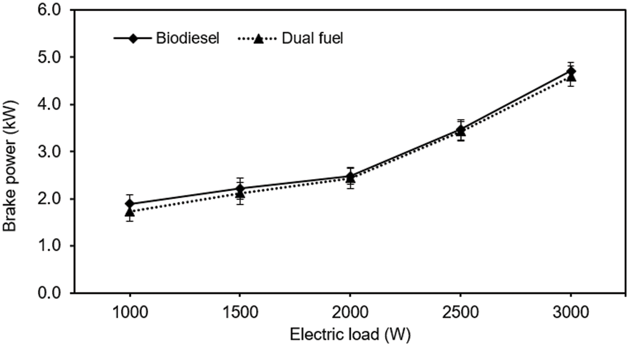
Figure 13: Brake power of small diesel engine
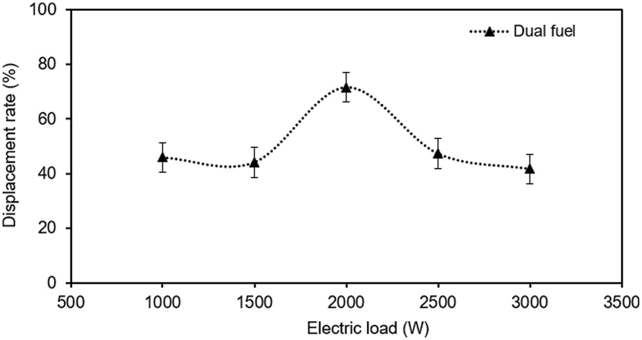
Figure 14: Biodiesel displacement rate of small diesel engine
3.6.3 Brake Thermal Efficiency
Fig. 15 shows the brake thermal efficiency of the engine operated on oil palm frond briquetted. The thermal efficiency is the amount of energy converted from biodiesel fuel combustion to electricity production. It was found that the brake thermal efficiency increased with an electric load increase because of the decreased average brake pressure in the engine. However, biodiesel had a higher thermal efficiency than dual fuel. The maximum thermal efficiency was determined to be 32.78% for biodiesel and 22.21% for dual fuel, respectively. However, in comparison with longan charcoal for producer gas production by downdraft gasification, it shows thermal efficiency in the producer gas engine at 23.50% and 26.90% for diesel engines at 1700 rpm [23].
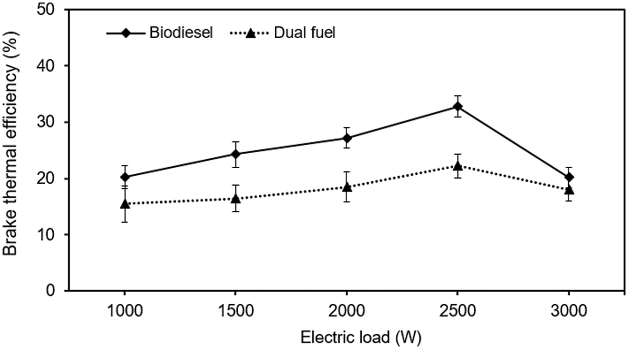
Figure 15: Brake thermal efficiency of small diesel engine
In this work, utilization of biomass via densification into briquettes and pellets was carried out. They were found to be good raw materials for gasification. The maximum cold gas efficiency of the downdraft gasifier was calculated to be 71.37% using wood pellets, the producer gas yield of 3.01 Nm3/kg and the low heating value of 3.85 MJ/Nm3. The yield of tar collected in the raw producer gas was quite high from gasifying the briquetted biomass fuel. Benzo(a)pyrene (C20H12), Chrysene (C18H12), Pyrene (C16H10), Phenanthrene (C14H10), 1-Methylnaphthalene (C11H10) were the main compounds in raw producer gas. Moreover, the study of small engines using biodiesel and dual fuel (biodiesel + producer gas from oil palm briquette) was also investigated. The maximum thermal efficiency of the engine was found to be 32.78% for biodiesel and 22.21% for dual fuel. It has the potential to reduce biodiesel consumption about 72%.
Acknowledgement: The authors would like to thank the National Research Council of Thailand (NRCT), School of Renewable Energy, Maejo University, and Chiang Mai University, Thailand.
Funding Statement: This project was supported by the National Research Council of Thailand (No. 2556NRCT531590).
Conflicts of Interest: The authors declare that they have no conflicts of interest to report regarding the present study.
References
1. Traivivatana, S., Wangjiraniran, W., Junlakarn, S., Wansophark, N. (2017). Thailand energy outlook for the Thailand integrated energy blueprint (TIEB). Energy Procedia, 138, 399–404. DOI 10.1016/j.egypro.2017.10.179. [Google Scholar] [CrossRef]
2. Bridgwater, A. V. (2012). Review of fast pyrolysis of biomass and product upgrading. Biomass and Bioenergy, 38, 68–94. DOI 10.1016/j.biombioe.2011.01.048. [Google Scholar] [CrossRef]
3. Rabiu, A. B., Lasode, O. A., Popoola, O. T., Babatunde, O., Ajimotokan, H. A. (2019). Densification of tropical wood residues for the development of solid fuels. Proceedings of the IAFOR International Conference on Sustainability, Energy & the Environment, pp. 15–25. Hawaii. [Google Scholar]
4. Akande, O. M., Olorunnisola, A. O. (2018). Potential of briquetting as a waste-management option for handling market-generated vegetable waste in Port Harcourt, Nigeria. Recycling, 3(2), 1–13. DOI 10.3390/recycling3020011. [Google Scholar] [CrossRef]
5. Ibitoye, S. E., Jen, T. C., Mahamood, R. M., Akinlabi, E. T. (2021). Densification of agro-residues for sustainable energy generation: An overview. Bioresources and Bioprocessing, 8(1), 1–19. DOI 10.1186/s40643-021-00427-w. [Google Scholar] [CrossRef]
6. Tumuluru, J. S., Wright, C. T., Hess, J. R., Kenney, K. L. (2011). A review of biomass densification systems to develop uniform feedstock commodities for bioenergy application. Biofuels, Bioproducts and Biorefining, 5(6), 683–707. DOI 10.1002/bbb.324. [Google Scholar] [CrossRef]
7. Stelte, W., Holm, J. K., Sanadi, A. R., Barsberg, S., Ahrenfeldt, J. et al. (2011). A study of bonding and failure mechanisms in fuel pellets from different biomass resources. Biomass and Bioenergy, 35(2), 910–918. DOI 10.1016/j.biombioe.2010.11.003. [Google Scholar] [CrossRef]
8. Cong, H., Yao, Z., MaŠek, O., Meng, H., Sheng, C. et al. (2021). Co-combustion, co-densification, and pollutant emission characteristics of charcoal-based briquettes prepared using bio-tar as a binder. Fuel, 287, 1–10. DOI 10.1016/j.fuel.2020.119512. [Google Scholar] [CrossRef]
9. Sharma, H. B., Dubey, B. K. (2020). Binderless fuel pellets from hydrothermal carbonization of municipal yard waste: Effect of severity factor on the hydrochar pellets properties. Journal of Cleaner Production, 277, 1–16. DOI 10.1016/j.jclepro.2020.124295. [Google Scholar] [CrossRef]
10. Ajimotokan, H., Ibitoye, S., Odusote, J., Adesoye, O., Omoniyi, P. (2019). Physico-mechanical characterisation of fuel briquettes made from blends of corncob and rice husk. Journal of Physics: Conference Series, 1378, 1–12. DOI 10.1088/1742-6596/1378/2/022008. [Google Scholar] [CrossRef]
11. Wzorek, M., Junga, R., Yilmaz, E., Niemiec, P. (2021). Combustion behavior and mechanical properties of pellets derived from blends of animal manure and lignocellulosic biomass. Journal of Environmental Management, 290, 1–8. DOI 10.1016/j.jenvman.2021.112487. [Google Scholar] [CrossRef]
12. Navalta, C. J. L. G., Banaag, K. G. C., Von Adrian, O. R., Go, A. W., Cabatingan, L. K. et al. (2020). Solid fuel from co-briquetting of sugarcane bagasse and rice bran. Renewable Energy, 147, 1941–1958. DOI 10.1016/j.renene.2019.09.129. [Google Scholar] [CrossRef]
13. Yang, I., Cooke-Willis, M., Song, B., Hall, P. (2021). Densification of torrefied pinus radiata sawdust as a solid biofuel: Effect of key variables on the durability and hydrophobicity of briquettes. Fuel Processing Technology, 214, 1–9. DOI 10.1016/j.fuproc.2020.106719. [Google Scholar] [CrossRef]
14. Pareek, D., Narnaware, S., Joshi, A., Verma, V. K. (2011). Gasification of crop residue briquettes in an open core down-draft gasifier. Journal of Agricultural Engineering, 48(2), 30–33. [Google Scholar]
15. Sasujit, K., Dussadee, N., Homdoung, N., Ramaraj, R., Kiatsiriroat, T. (2017). Waste-to-energy: Producer gas production from fuel briquette of energy crop in Thailand. International Energy Journal, 17(1), 37–46. [Google Scholar]
16. Nyakuma, B. B., Mazangi, M., Tuan Abdullah, T. A., Johari, A., Ahmad, A. et al. (2015). Gasification of empty fruit bunch briquettes in a fixed bed tubular reactor for hydrogen production. Applied Mechanics and Materials, 699, 534–539. DOI 10.4028/www.scientific.net/AMM.699.534. [Google Scholar] [CrossRef]
17. Dzombo, D., Kiplimo, R., Kiplagat, J. (2014). Use of biomass gas in running internal combustion engine to generate electricity--A review. Proceedings of Mechanical Engineering Conference on Sustainable Research and Innovation, 5, 89–95. [Google Scholar]
18. Homdoung, N., Dussadee, N., Sasujit, K., Kiatsiriroat, T., Tippayawong, N. (2019). Performance investigation of a gasifier and gas engine system operated on municipal solid waste briquettes. International Journal of Renewable Energy Development, 8(2), 179–184. DOI 10.14710/ijred.8.2.179-184. [Google Scholar] [CrossRef]
19. Kjellstroem, B., Arvidson, A., Forslund, H., Martinac, I. (2005). Renewable energy technologies for decentralized rural electricity services. SEI Climate and Energy Programme, Stockholm, Sweden: Swedish Environment Institute (SEI). [Google Scholar]
20. Atnaw, S. M., Kueh, S. C., Sulaiman, S. A. (2014). Study on tar generated from downdraft gasification of oil palm fronds. The Scientific World Journal, 2014, 1–9. [Google Scholar]
21. Basu, P. (2018). Biomass gasification, pyrolysis and torrefaction: Practical design and theory. USA: Academic Press. [Google Scholar]
22. British Standard (2007). Biomass gasification. Tar and particles in product gases. Sampling and analysis. DD CEN/TS 15439:2006. London: UK: British Standard Institute. [Google Scholar]
23. Homdoung, N., Tippayawong, N., Dussadee, N. (2015). Performance and emissions of a modified small engine operated on producer gas. Energy Conversion and Management, 94, 286–292. DOI 10.1016/j.enconman.2015.01.078. [Google Scholar] [CrossRef]
24. Shelke, G. N., Mahanta, P. (2016). Feasibility study on utilization of biomass briquette in a conventional downdraft gasifier. International Energy Journal, 15(4), 157–166. [Google Scholar]
25. Sheth, P. N., Babu, B. (2009). Experimental studies on producer gas generation from wood waste in a downdraft biomass gasifier. Bioresource Technology, 100, 3127–3133. DOI 10.1016/j.biortech.2009.01.024. [Google Scholar] [CrossRef]
26. Punnarapong, P., Promwungkwa, A., Tippayawong, N. (2017). Development and performance evaluation of a biomass gasification system for ceramic firing process. Energy Procedia, 110, 53–58. DOI 10.1016/j.egypro.2017.03.105. [Google Scholar] [CrossRef]
27. Chawdhury, M. A., Mahkamov, K. (2011). Development of a small downdraft biomass gasifier for developing countries. Journal of Scientific Research, 3(1), 51–64. DOI 10.3329/jsr.v3i1.5613. [Google Scholar] [CrossRef]
28. Yaman, S. (2004). Pyrolysis of biomass to produce fuels and chemical feedstocks. Energy Conversion and Management, 45(5), 651–671. DOI 10.1016/S0196-8904(03)00177-8. [Google Scholar] [CrossRef]
29. Anis, S., Zainal, Z. (2011). Tar reduction in biomass producer gas via mechanical, catalytic and thermal methods: A review. Renewable and Sustainable Energy Reviews, 15(5), 2355–2377. DOI 10.1016/j.rser.2011.02.018. [Google Scholar] [CrossRef]
30. Ogi, T., Nakanishi, M., Fukuda, Y., Matsumoto, K. (2013). Gasification of oil palm residues (empty fruit bunch) in an entrained-flow gasifier. Fuel, 104, 28–35. DOI 10.1016/j.fuel.2010.08.028. [Google Scholar] [CrossRef]
 | This work is licensed under a Creative Commons Attribution 4.0 International License, which permits unrestricted use, distribution, and reproduction in any medium, provided the original work is properly cited. |