Materials Processing
| Fluid Dynamics & Materials Processing |
DOI: 10.32604/fdmp.2021.013521
ARTICLE
Lattice Boltzmann Simulation of Nanoparticle Transport and Attachment in a Microchannel Heat Sink
1School of Energy and Environmental Engineering, University of Science and Technology Beijing, Beijing, 100083, China
2Shunde Graduate School of University of Science and Technology Beijing, Shunde, 528399, China
*Corresponding Author: Kai Yue. Email: yuekai@ustb.edu.cn
Received: 10 August 2020; Accepted: 24 December 2020
Abstract: The heat transfer performances of a microchannel heat sink in the presence of a nanofluid can be affected by the attachment of nanoparticle (NP) on the microchannel wall. In this study, the mechanisms underlying NP transport and attachment are comprehensively analyzed by means of a coupled double-distribution-function lattice Boltzmann model combined with lattice-gas automata. Using this approach, the temperature distribution and the two-phase flow pattern are obtained for different values of the influential parameters. The results indicate that the number of attached NPs decrease exponentially as their diameter and the fluid velocity grow. An increase in the wall temperature leads to an increase of the attached NPs, e.g., the Al2O3 NPs attached on the CuO microchannel wall increases by 105.8% in the range between 293 K and 343 K. There are more attached NPs in microchannels with an irregular structure. The tendency of SiO2 NP to attach to the PDMS (polydimethylsiloxane), Fe and Cu walls is less significant than that for Al2O3 and CuO NP; Moreover, NPs detach from the PDMS microchannel wall more easily than from the Cu and Fe microchannel walls. The SiO2 attachment layer has the greatest influence on the heat transfer performance although its thickness is thinner than that for Al2O3 and CuO NPs under the same conditions.
Keywords: Double-distribution-function lattice Boltzmann method; lattice gas automata; microchannel; nanoparticle (NP); attachment
In recent years, nanofluids that comprise a base fluid and nano-sized particles have been widely applied in microelectronics, aerospace, medical treatment, clean energy and chemical engineering owing to high specific surface area and high thermal conductivity [1–5]. For example, nanofluids can be used as potential heat transfer fluids in microchannel heat sinks due to their enhanced thermophysical properties [6,7]. Carbon nanotubes, copper oxide, aluminium oxide and silicon dioxide [8,9] are commonly used for nanoparticles while organic fluids and water are utilized for based fluid [10]. The attachment of nanoparticles (NPs) to microchannel walls, which has a significant influence on the heat transfer performance of microchannel devices in microflow systems, is an unavoidable phenomenon during the NP transport process in microchannels and probably results in abrasion and clogging of the equipment. Therefore, obtaining a good understanding of the behaviors of NP transport and attachment in microchannels is of great importance.
The NP attachment to a microchannel wall surface is often considered as a two-step process [11]. First, the NPs arrive at the vicinity of the surface via the action of the fluids. Then, the NPs attachment occurs through the specific interaction between the NPs and the microchannel surface. The transport and attachment of NPs may be affected by many factors, such as fluid temperature, NP size and material, fluid velocity, microchannel material and wall structure. Many attempts have been made to investigate the transport and attachment of NPs in microchannels. Wu et al. [12] found in experiments that Al2O3 NPs attached easily to the inner wall of a microchannel with the increase of the wall temperature. Decuzzi et al. [13] analyzed the effect of NP volume on the specific adhesive interaction between a non-spherical NP and a substrate and found that there existed an optimal volume for the maximum adhesive strength for a fixed shape of NP. Toy et al. [14] demonstrated experimentally that different NP materials displayed different depositions. Jeong et al. [15] and Lima et al. [16] found that fluid velocity had significant effects on NP transport and attachment for particles smaller than 600 nm. Thomas et al. [17] reported the effect of channel geometry on NP distribution in the bifurcation microchannel. Shah et al. [18] modeled the attachment dynamics of spherical and rod NPs and found that rod-shaped NPs had higher deposition probability than spherical NPs. Haunet et al. [19] analyzed experimentally the effect of the surface conditions of NPs and substrate on the attachment and detachment behaviors of a 210 nm NP. Generally, the NP attachment mechanism and forces acting on NPs in microchannels have not previously been comprehensively considered in numerical simulations and more detailed in-depth analysis of the effects of key influencing factors is needed.
To numerically simulate the particle movement, conventional numerical methods, such as Navier–Stokes equations for flow fields and Lagrangian approaches for particle motion, are usually employed to simulate liquid-particle flows [20–22]. The behaviors of NP transport and attachment in microchannels are complicated because a number of factors may strongly influence the particle movement, such as gravity/buoyancy, electrostatic force, van der Waals force [23], Saffman lift force [24,25], Brownian diffusion and local fluid velocity [26,27]. From a microscopic or mesoscopic perspective, the effect of the interactions between the fluid and NPs of the mixture can be considered better using the lattice Boltzmann method (LBM) and [28] the lattice gas automata (LGA) probabilistic model [29]. LBM is suitable for analyzing the mesoscopic characteristics of nanofluid transport in microchannels with complex structure and has high computational efficiency, in which a NP may stay at the original node or propagate to its nearest neighbor node, depending on the probability of NP motion. Furthermore, a corresponding double distribution approach [30,31] based on LBM was proposed to describe fluid flow and heat transfer process in mesoscopic systems.
This study aims to explore the mechanisms and behaviors of NP transport and attachment in a microchannel heat sink. A coupled double-distribution-function lattice Boltzmann model combined with LGA was established to numerically analyze the velocity and temperature distributions, NP transport in microchannels and NP attachment to channel walls. Furthermore, the investigation into the critical factors influencing the NP attachment to the channel wall was carried out, including NP size, flow velocity, NP and channel materials and channel structure. On this basis, we analyzed the effect of attachment layers on heat transfer performance of a microchannel heat sink with different NP and channel materials.
As shown in Figs. 1a and 1b, there were 80000 NPs in the nanofluid with a low volume fraction (0.1%) and the NPs were injected in a 3.2 mm × 0.2 mm microchannel. Cold nanofluids passed through microchannels and carry away heat generated from MEMS devices. The velocity and temperature of the nanofluid were u0 and t0. It was assumed that the temperatures of the upper and lower walls were the same tw. The NPs concerned in this work are SiO2, Al2O3, and CuO NPs, and channel wall materials are Fe, Cu, and polydimethylsiloxane (PDMS).
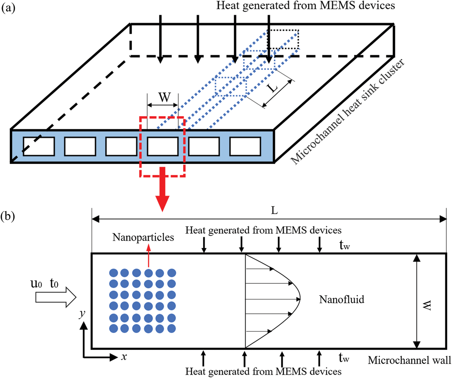
Figure 1: Schematic diagram, (a) Geometrical model and (b) Physical model of the microchannel
The D2Q9 lattice model was utilized and the evolution equations [30] were written as:
where fi = f (x, ci, t) is the discrete density distribution function and gi = g (x, ci, t) is the discrete temperature distribution function.
The Chapman–Enskog expansion method [31] was applied to obtain the corresponding macroscopic equations of the fluid flow. The macroscopic density, velocity and temperature were calculated by
2.1 Modeling of NP Transport and Attachment
The NP transport in microchannels can be influenced by the flow resistance, gravity/buoyancy, van der Waals force, Saffman lift force, static electricity and Brownian motion. Compared with other forces acting on the NPs, the electrostatic and van der Waals interaction forces between the NPs, gravity and buoyancy can be neglected [31] for the NPs with diameter less than 200 nm, and the influence of NP rotation was also negligible. The NP movement was described by the following:
where ap and up represent the acceleration and velocity of the NP, respectively; up was calculated by up = dxp/dt; u represents the velocity of the fluid and τp represents the relaxation time; ab, aad and alift are the accelerations caused by Brownian force, adhesive force and Saffman lift force, respectively. ζ represents the Gaussian random distribution number with a mean of 0 and a standard deviation of 1.
The Brownian force acting on NPs is expressed as Fb = 2kbT/dp [37]. When the NPs were transported to the vicinity of the microchannel walls, the adhesive force caused by the van der Waals force enabled the NP attachment [38,39]. In consideration of the influence of surface roughness on the adhesive force [40], the adhesive force could be described as:
where A is the Hamaker constant listed in Tab. 1 and dp represents the diameter of NP; D0 is the distance of the closest approach between the NPs and the microchannel wall, and it is assumed to be D0 = 0.6 nm; r and R are the radius of the asperity and NP, respectively [41,42].
Table 1: List of Hamaker constant (×10-20J) used in the model [39,43–46]
The Saffman lift force for a NP was given as [43,44]:
where, ρ and v represent the density and kinematic viscosity of the carrier phase, respectively.
The NPs were dispersed in water to produce nanofluids and the thermophysical parameters for different NPs are listed in Tab. 2.
Table 2: List of parameters used in the model [47,48]
By integrating Eq. (3) and up = dxp/dt, the NP velocity and displacement equation could be obtained as follows [45,46]:
where the time interval of NP transport is Δt = 10-5 s, xp* and up* represent the position and velocity of a NP, respectively.
The LGA was applied to calculate its actual migration position in the lattice [49,50]. The NPs were confined to move on the grid nodes and the probability Pi of NPs migrating to adjacent nodes was obtained from Eq. (8).
where △xp = xp* − xp. and ei represents the discrete velocity of D2Q9 model. The actual position xlp on the grid nodes was calculated as follows:
where λi is a Boolean variable which is equal to 1 with probability Pi.
The physical units were converted to dimensionless lattice units based on the same dimensionless criterion number Re [51,52]. The characteristic length was the microchannel width and the characteristic velocity was the maximum fluid velocity. A grid-independence test was carried out and the mean Nusselt numbers was selected as criteria [53]. Four different meshes listed in Tab. 3 were checked and a grid system with 3200 × 200 (a grid spacing of 0.2 μm) was finally chosen for the simulations.
Table 3: Comparison of Nu for different mesh resolutions at Re = 100

In the simulations, the numbers of NPs attaching to the microchannel wall at different times were counted in consideration of the randomness and uncertainty of Brownian motion of particles. To validate the correctness of the established model, the trajectory of a 3 mm-diameter particle in a square lid-driven cavity was simulated. There are similar moving trajectories between the simulated result and the experimental result as shown in Fig. 2. Furthermore, the model was validated by comparing the simulated Nusselt number with the result obtained from Balakrishnan et al. [54] and a good agreement was obtained.
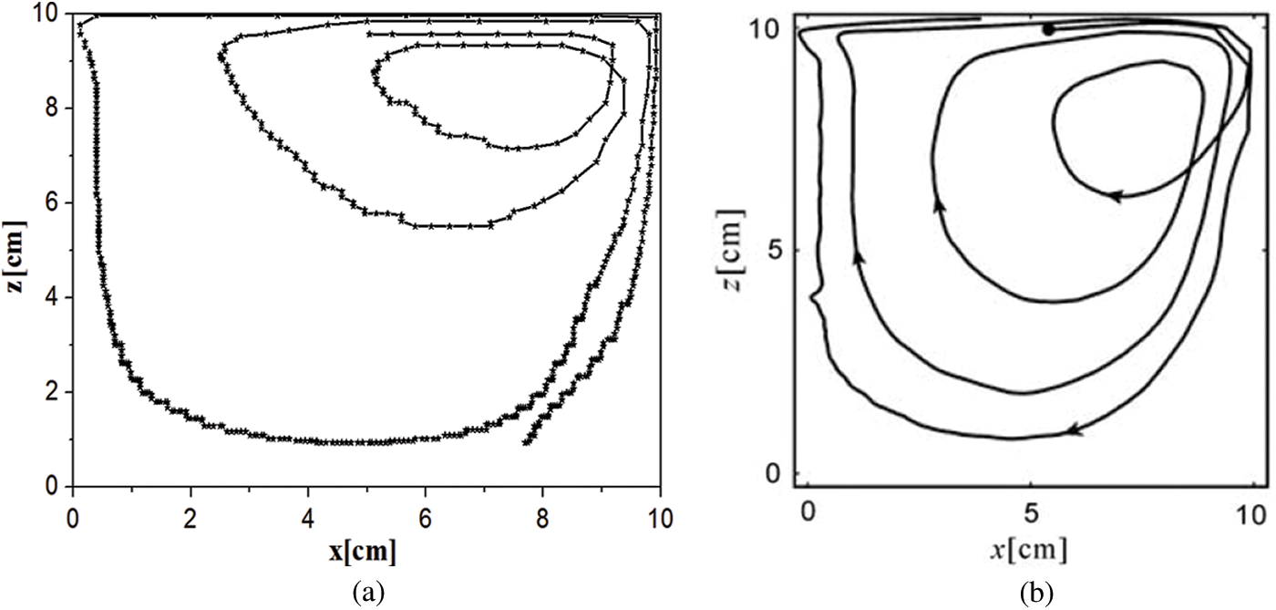
Figure 2: Particle trajectories in a lid-driven cavity: (a) Obtained by the simulation in this study and (b) Obtained from Tsorng et al. [55]
3.1 Effects of NP Diameter and Fluid Velocity
A change in NP diameter can significantly influence the values of drag force, Brownian force, van der Waals force, and Saffman lift force acting on the NPs. We analyzed the effect of NP size on the attachment behavior of SiO2 NPs in the PDMS microchannel at the Reynolds number of 100. As shown in Fig. 3a, compared with the 10 nm NP at time t = 3.0 s, the numbers of 25, 50, 100, and 150 nm NPs attaching to the microchannel wall decreased by 34.69%, 81.59%, 93.93% and 97.91%, respectively. The smaller NP diameters could cause more NPs to attach to the microchannel wall due to the increase in the Brownian force, improving the probability of the NP transport to the microchannel wall.
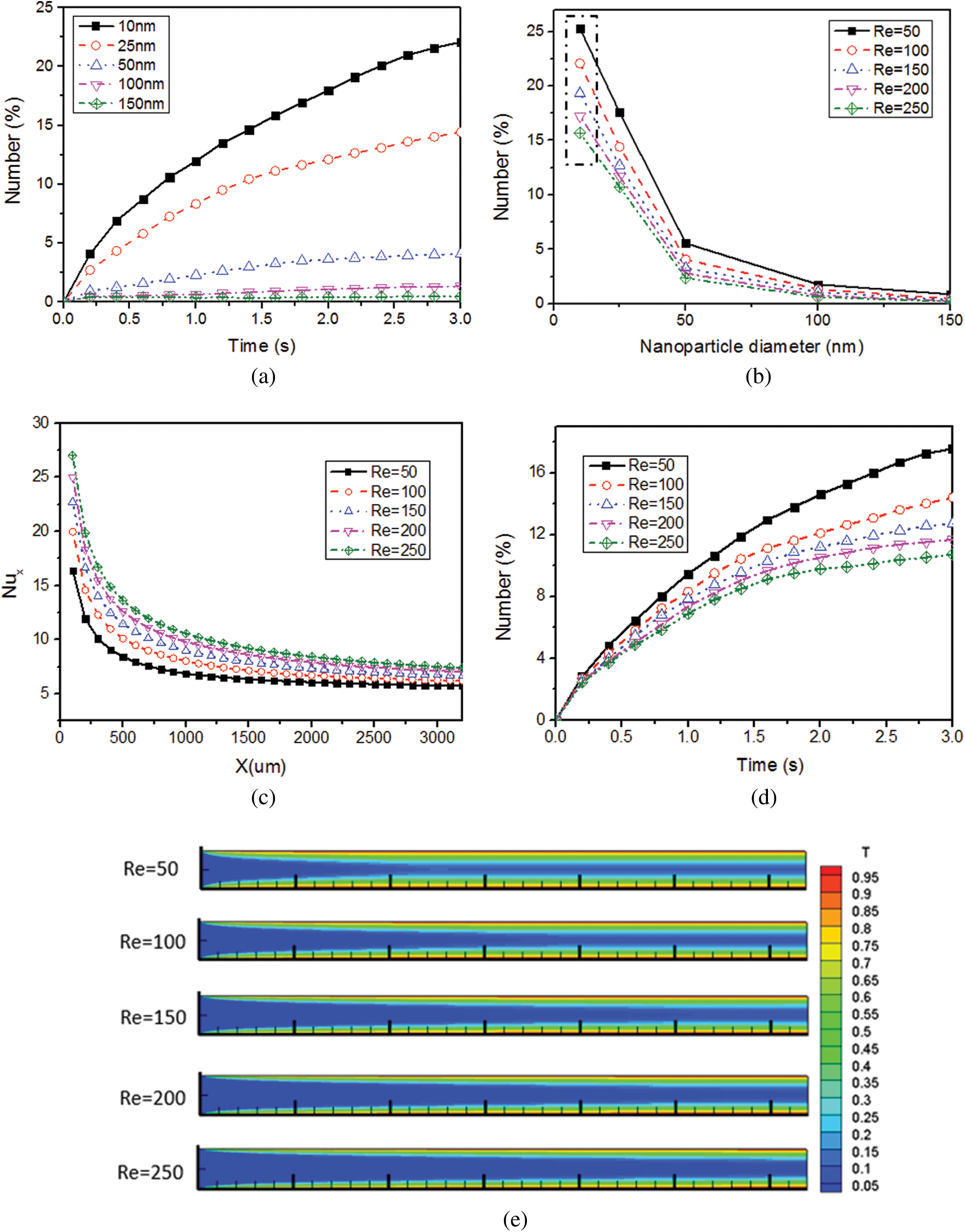
Figure 3: Effect of NP diameter on the number of attached NPs, (a) Over time and (b) At different Reynolds numbers; Effect of the fluid Reynolds number on, (c) The mean Nusselt number Nux and (d) The number of attached NPs; (e) Dimensionless temperature distribution in the microchannel at different fluid Reynolds numbers
The number of attached NPs with diameter larger than 25 nm exhibited an approximately exponentially decay with the increase of the NP diameter (Fig. 3b) at different Reynolds numbers. However, it is worthy of noting that its decay rate became slower when the NP diameter changed from 25 nm to 10 nm, which was inconsistent with the exponential trend. This is because the Brownian forces increased with the decrease of the NP diameter whereas the adhesive forces decreased, and it was more probable for the attached 10 nm NPs to detach from the microchannel when its Brownian force was greater than the adhesive force. The results were consistent with that proposed by Jeonget et al. [15,16] in which particles with lower shear rate and smaller size showed higher attachment possibility.
When the inflow temperature was 293 K and wall temperature was 343 K, the simulation results for 10 nm SiO2 NPs in the PDMS microchannel show that the Nux increased with the increase of Reynolds number (Fig. 3c). Comparing with Re = 50, the Nux increased by 8.01%, 15.94%, 22.62% and 28.83% for every 50 increase in fluid Reynolds number, respectively. The heat transfer performance increased with the increase of fluid velocity. As shown in Fig. 3d, the smaller the fluid velocity, the more NPs would attach to the microchannel. At time t = 3.0 s, the number of attached NPs decreased by 17.96%, 11.58%, 8.66% and 8.29%. The high fluid temperature (Fig. 3e) caused by low fluid velocity intensified the NP Brownian motion and led to greater probability of NP transport to the microchannel walls. Moreover, a low fluid velocity could extend the transport time of NPs in the microchannel and make it more probable for the NPs to move and attach to microchannel walls. To some degree, an increase in fluid velocity reduced the NP attachment and increased the heat transfer performance. However, the pump power of microchannel heat exchangers would increase with the increase of fluid velocity [56].
3.2 Effects of NP Material and Channel Material
Equations in display format are separated from the paragraphs of the text. Equations should be flushed to the left of the column. Equations should be made editable. Displayed equations should be numbered consecutively, using Arabic numbers in parentheses. See Eq. (1) for an example. The number should be aligned to the right margin.
The interaction between the NPs and channel wall is evidently affected by the NP material and channel material, which cannot be ignored for exploring how the NPs attach to the channel wall. In view of the commonly used materials in the microflow systems [57], the attachment behaviors of the Al2O3-H2O, CuO-H2O, and SiO2-H2O nanofluids in the PDMS, Fe, and Cu microchannels were analyzed. Figs. 4a–4c show the effects of NP and channel materials on the number of the attached NPs when the fluid temperature at the inlet and wall temperature were set to 293 K and 343, respectively. The numbers of SiO2 NPs attached on the PDMS and Fe microchannel walls decreased by 45.99% and 1.45%, respectively, compared with those on the Cu microchannel wall at the Reynolds number of 100. The SiO2 NPs had lowest attachment to the PDMS microchannel, followed by that to the Fe microchannel, and the attachment to the Cu microchannel was the highest. The reason is that after the NPs came into contact with the microchannel wall, the movement of the attached NPs was mainly affected by the Brownian force and the interaction between the SiO2 NPs and the microchannel wall, and this interaction for the Cu wall was strongest in comparison to those for the PDMS and Fe walls.
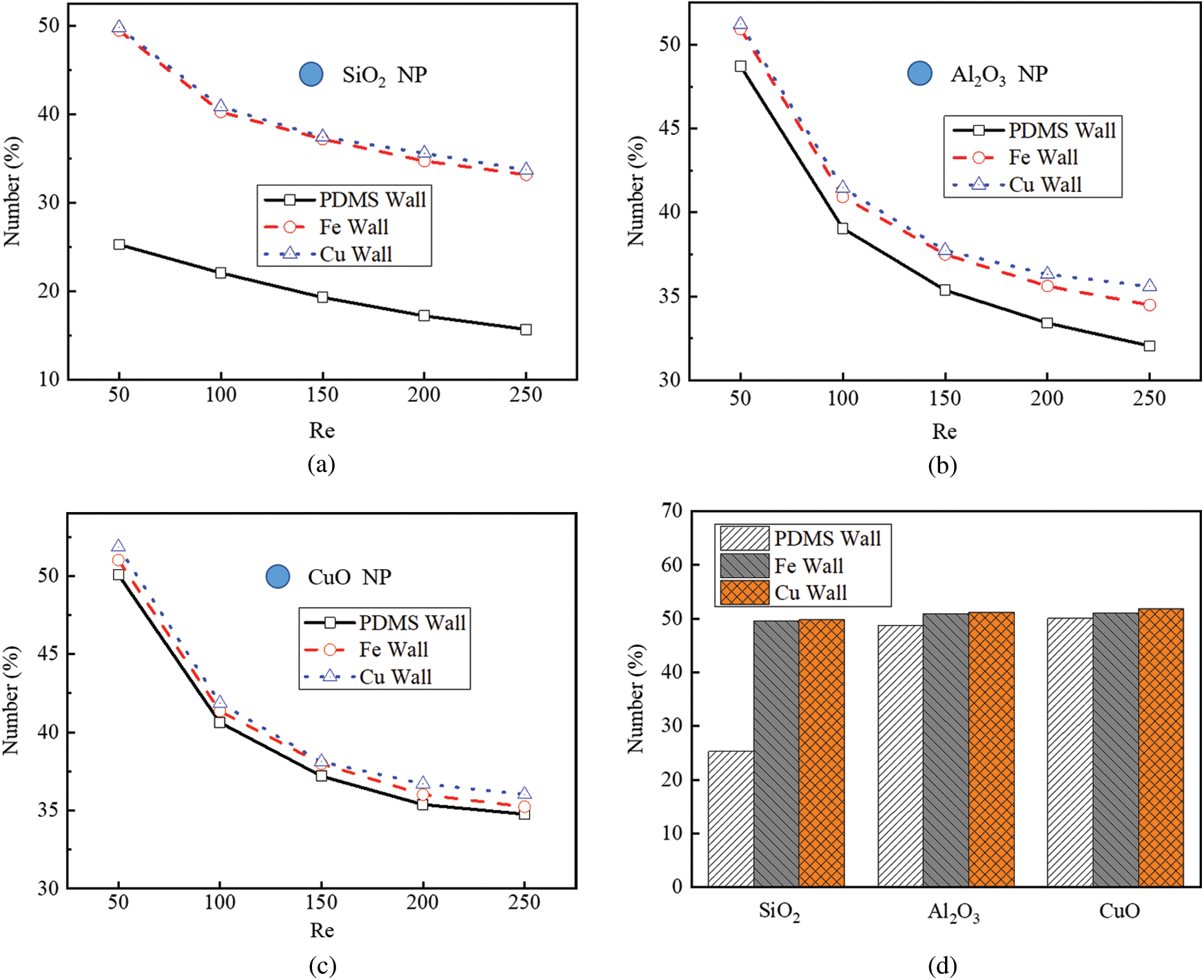
Figure 4: Effect of NP and channel materials on the number of attached NPs, (a) SiO2 NPs; (b) Al2O3 NPs; (c) CuO NPs; (d) Different NPs in different channels
Fig. 4d shows that when the Reynolds number was set to 50, the numbers of the attached Al2O3 and SiO2 NPs decreased by 2.70% and 49.52% in the PDMS microchannel, respectively, compared with the CuO NPs. Furthermore, the numbers of the SiO2 NPs attached to the Cu and Fe microchannels increased by 95.80% and 97.08%, compared with those to the PDMS microchannel, respectively. When the SiO2 NPs migrated in the PDMS microchannel, the number of the attached NPs was the least compared with those of all the other groups. In contrast, when CuO NPs migrated in the Cu microchannel, the number of the attached NPs was the largest. The number of attached NPs is positively correlated with the Hamaker constant, and the Hamaker constant between CuO NPs and Cu wall was the maximum compared with others.
3.3 Effect of Microchannel Wall Temperature
The wall temperature will inevitably affect the Brownian force acting on NPs and the fluid properties. We analyzed its effect on the attachment of Al2O3 NPs in the Cu microchannel within the temperature range from 293 K to 343 K at a Reynolds number of 100. As shown in Fig. 5a, the higher fluid temperature caused more NPs to attach to the wall. At time t =3.0 s, the number of attached NPs increased by 29.38%, 21.29%, 15.03%, 7.75% and 5.89%, respectively. The fluid viscosity decreased with the increase of fluid temperature and the low fluid viscosity led to the low flow resistance acting on the NPs. It was easier for the NPs to migrate to the microchannel wall. Moreover, an increase in fluid temperature could intensify the NP Brownian movement. Taken together, the attachment probability became greater as the fluid temperature increased. Wu et al. [12] obtained similar results that NPs attached easily to the wall with the increase of temperature.
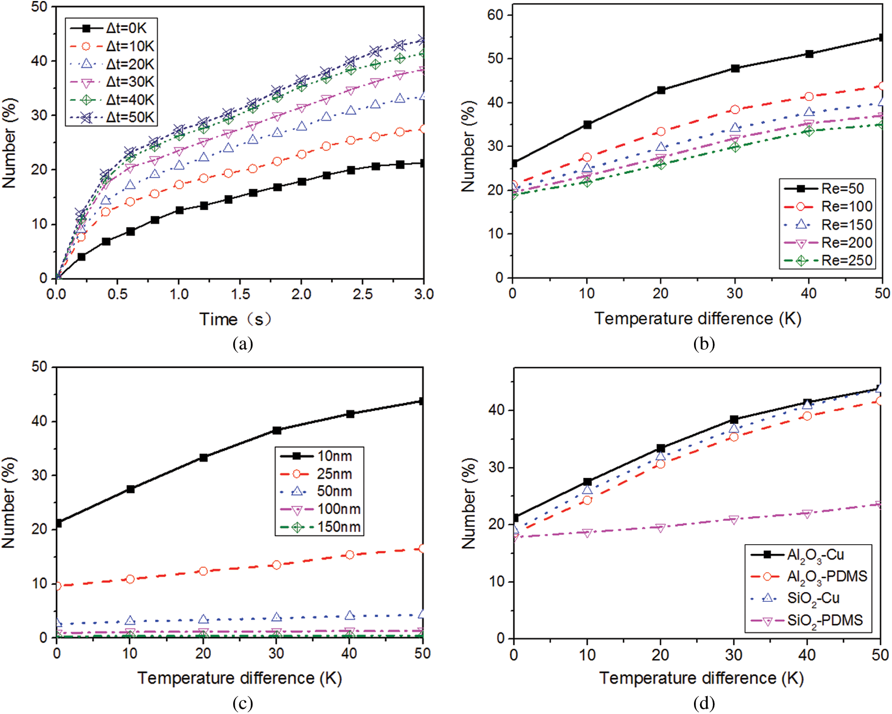
Figure 5: Effect of temperature on the number of attached NPs, (a) with the change of time; (b) with the change of fluid velocity; (c) with the change of NP diameter; (d) for different NP-channel groups
Figs. 5b and 5c show the relationships between temperature difference and the number of attached Al2O3 NPs at different Reynolds numbers and NP diameters. For every 10 K increase in wall temperature, the number of attached NPs showed a variation of logarithmically increasing trend. When the Reynolds number increased by 50 and the temperature difference decreased from 50 K to 0 K, the number reduced by 52.21%, 51.41%, 48.94%, 47.22% and 45.91%, respectively. The effect of the temperature changes on NP attachment became weaker with the increase of the Reynolds number. A possible reason is that an increase in Reynolds number led to stronger drag force acting on the NPs whereas it would weaken the effect of the Brownian force on NP attachment. For every 10 K increase in temperature difference, the number of attached 10 nm NPs increased by 36.92%, 34.75%, 20.60%, 14.94%, and 8.08%, respectively. However, the effect of wall temperature on NP attachment became smaller with increasing the NP diameter and it could be ignored for 100 nm and 150 nm NPs. One possible reason is that the inertia of NPs increased with the NP diameter, which resulted in the less effect of temperature changes on NP motion.
Fig. 5d shows the attachments of two typical NPs (10 nm SiO2 and Al2O3) to different microchannels (Cu and PDMS). In the PDMS microchannel, when the difference of temperatures between the inlet fluid and the microchannel wall increased from 0 K to 50 K, the numbers of attached Al2O3 NPs and SiO2 NPs increased by 123.90% and 32.49%, respectively. The temperature change of microchannel wall had greater influence on the number of attached Al2O3 NPs than that of SiO2 NPs. This is because the adhesive force between the Al2O3 NPs and PDMS microchannel was larger than that for SiO2 NPs, causing easier detachment for the attached SiO2 NPs. However, in the Cu microchannel, the changes in wall temperature had larger influence on the number of attached SiO2 NPs than that of Al2O3 NPs. When the temperature difference increased from 0 K to 50 K, the number of attached Al2O3 NPs and SiO2 NPs increased by 105.81% and 129.93%, respectively. The level of the Brownian movement of Al2O3 (3700 kg/cm3) NPs was weaker compared with that of the SiO2 (2200 kg/cm3) NPs due to the larger mass of Al2O3 NPs.
We established models of microchannels with irregular structures [35,53,58] to analyze its effect on NP attachment, as shown in Fig. 6a.
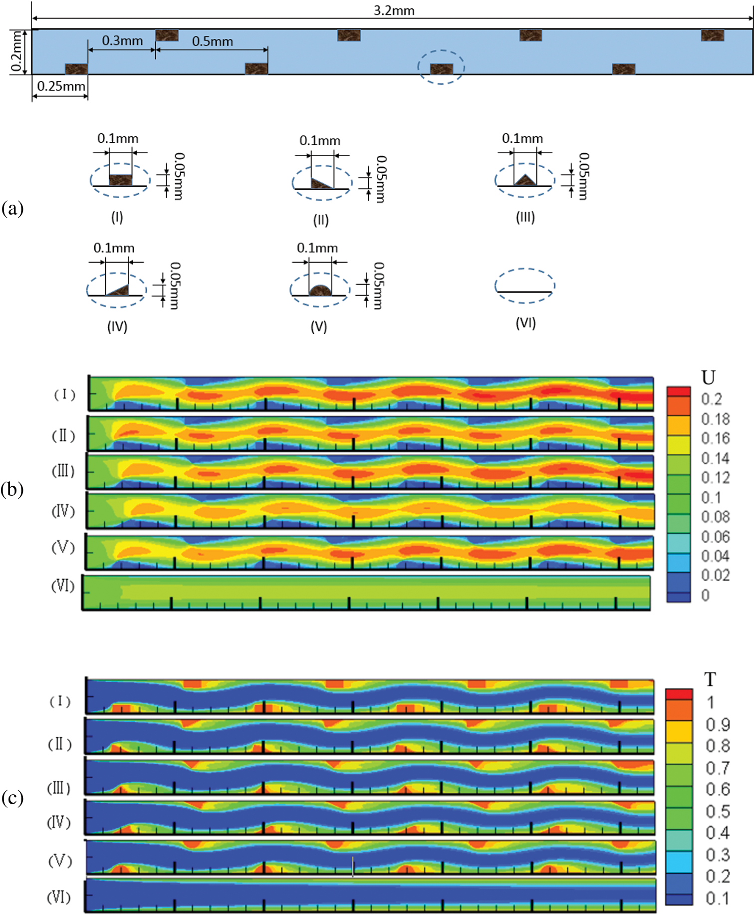
Figure 6: Effect of wall structure on the number of attached NPs (a) Structures of different microchannel wall; (b) Dimensionless velocity distribution; (c) Dimensionless temperature distribution in the microchannels (Re = 200)
In Figs. 6b and 6c, the maximum velocity appeared at the centerline in the smooth microchannel whereas it moved to the side without ribs for irregular wall structures and there was a low velocity area behind each rib. The velocity difference in the x-direction in microchannel (I) was slightly larger than others and the flow velocities in microchannels (I), (II), (III) and (V) were greater than those in microchannels (IV) and (VI). The velocity components along the centerline (Fig. 7a) show that the velocity in irregular microchannels was greater than that in the smooth microchannel. The velocity component in microchannel (IV) was lowest compared with those in other microchannels with ribs.
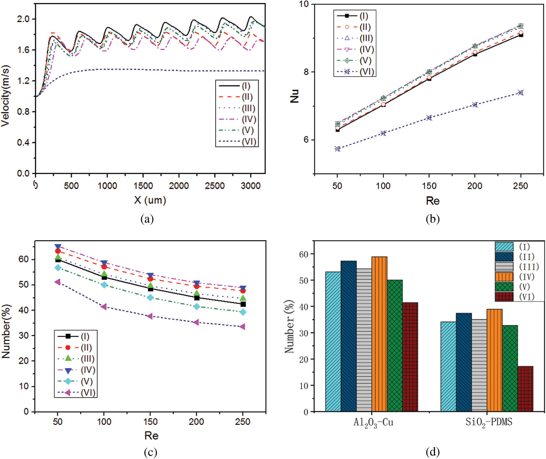
Figure 7: Effect of wall structure on the number of attached NPs, (a) Velocity component in x-direction at the centerline of microchannels (Re = 200); (b) Variation of Nu with Re; (c) Variation of the number of attached NPs (Re = 200); (d) For different NP-channel groups
To analyze the heat transfer performance, the dimensionless temperature ((T-T0)/(Tw-T0)) was calculated (Fig. 6c). Due to the small velocity behind each rib, the mean temperature of this region was greater than other parts of the flow filed. The low temperature regions in microchannels (III) and (IV) were slightly larger than those in other microchannels. As shown in Fig. 7b, the mean Nusselt numbers for the irregular microchannels were larger than that for the smooth microchannel. Compared with microchannel (VI), the mean Nusselt numbers of microchannels (I), (II), (III), (IV) and (V) increased by 21.12%, 21.99%, 24.35%, 24.69% and 24.49%, respectively, because the ribs not only disturbed the fluid flow but also increased the heat transfer area.
It is shown in Fig. 7c that the number of NPs attached to microchannel (IV) wall was the largest among all the microchannels. At the Reynolds number of 200, the number of attached NPs in microchannels (I), (II), (III), (IV) and (V) increased by 28.38%, 40.20%, 31.96%, 44.17% and 17.69%, respectively, compared with that in microchannel (VI) due to the larger region of low velocity. The offset rib increased the heat transfer area and the increased fluid temperature and intensified the NP Brownian motion. Similarly, there were more NPs attached to microchannels (II) and (IV) than microchannels (I), (III) and (V). Fig. 7d shows that the relative variation of SiO2 NP attachment in different microchannels was the same as that for Al2O3 NPs. The difference in NP attachment was impacted by the different interactions between SiO2-Cu and Al2O3-PDMS.
3.5 Effect of NP Attachment on Heat Transfer Performance
A simplified model (Fig. 8a) was established to analyze the effect of NP attachment layer. The left boundary was set to a t0 = 293 K and the right boundary of the attachment layer was set to an adiabatic condition. A constant temperature of tw was applied to the upper and lower walls. The thicknesses of the attachment layers for different NPs were deduced from the number of attached NPs obtained in Section 3.2 in view of burdensome calculation. Q/Q0 was defined to characterize the effect of NP attachment on the heat transfer performance, where Q0 and Q represent the heat exchanging quantity before and after the NP attachment.
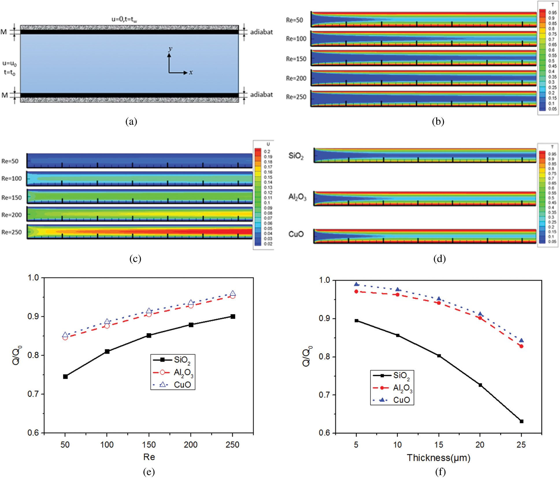
Figure 8: Effect of NP attachment on heat transfer performance, (a) Simplified model; (b) and (c) Temperature and velocity distributions after NP attachment; (d) Temperature distributions for different NPs; (e) Q/Q0 at different Reynolds numbers; (f) Q/Q0 for different NPs
The temperature and the velocity distributions are shown in Figs. 8b and 8c. At the Reynolds number of 50, the attachment layer thickness of SiO2, Al2O3, and CuO NPs were set to 13 μm, 24 μm and 2 μm, respectively. Fig. 8d shows that even if the attachment layer thicknesses of Al2O3 and CuO NPs were larger than that of SiO2 NPs, the temperature distributions in the heat sinks with Al2O3 and CuO NPs were more uniform. The SiO2 attachment layer had the greatest influence on heat transfer performance. A major reason for this is that the thermal conductivities of Al2O3 and CuO NPs are 20.7 and 54.4 times larger than that of SiO2 NPs, respectively, and the SiO2 attachment layer had a larger thermal resistance. For Al2O3 and CuO NPs, the average outlet temperature was 29.46% and 32.83% higher than that of the SiO2 NPs, respectively.
Fig. 8e shows that the value of Q/Q0 increased with the Reynolds number. This is because a higher Reynolds number led to a smaller number of attached NPs and thinner attachment layer, corresponding to a smaller thermal resistance. The values of Q/Q0 for the thickness of 5 μm, 10 μm, 15 μm, 20 μm and 25 μm (Fig. 8f) decreased by 4.33%, 6.21%, 9.52% and 13.05%, respectively, for the SiO2 attachment layer. Moreover, compared with the SiO2 NPs, the values of Q/Q0 of the sink using the Al2O3 and CuO NPs increased by 24.00% and 25.40%, respectively, when the attachment layer thickness was 20 μm.
This study investigated the mechanism and behaviors of NP attachment in a microchannel heat sink. The numerical simulation of NP transport in fluid flow and temperature distribution were carried out by the LBM-LGA method and the influences of key factors on NP attachment were deeply analyzed. It is concluded that the relatively larger NP size and higher Reynolds number within the applicable range (from 50 to 250) can decrease the number of attached NPs. The effects of wall temperature and irregular structure should be comprehensively considered because the NP attachment may be enhanced under the given temperature and structure condition although this condition is originally designed for improving heat transfer performance of the sink. The NP attachment and its effect on the heat transfer performance could be obviously affected by NP and microchannel materials. The attachment layer of SiO2 NPs was the thinnest whereas it had the greatest influence on the heat transfer performance compared with Al2O3 and CuO NPs under the same conditions. Results of this study can provide instructive information on the designs of NP and channel structure, material selection and operating parameter optimization for high efficiency application of a microchannel heat sink. In addition, the proposed model can be also used to investigate the transport behavior of nanocarriers in microvessels for NP-mediated drug delivery application. Our future work will be focused on the improvement of the model for its limitation of NP volume fraction rate.
Funding Statement: This work was supported by the National Natural Science Foundation of China for financial support (No. 51890894) and Scientific and Technological Innovation Foundation of Shunde Graduate School, USTB (Grant No. BK19AE012).
Conflicts of Interest: The authors declare that they have no conflicts of interest to report regarding the present study.
1. Chein, R., Huang, G. (2005). Analysis of microchannel heat sink performance using nanofluids. Applied Thermal Engineering, 25(17–18), 3104–3114. DOI 10.1016/j.applthermaleng.2005.03.008. [Google Scholar] [CrossRef]
2. Eastman, J. A., Choi, S. U. S., Li, S., Yu, W., Thompson, L. J. (2001). Anomalously increased effective thermal conductivities of ethylene glycol-based nanofluids containing copper nanoparticles. Applied Physics Letters, 78(6), 718–720. DOI 10.1063/1.1341218. [Google Scholar] [CrossRef]
3. Godson, L., Raja, B., Lal, D. M., Wongwises, S. E. A. (2010). Enhancement of heat transfer using nanofluids—An overview. Renewable and Sustainable Energy Reviews, 14(2), 629–641. DOI 10.1016/j.rser.2009.10.004. [Google Scholar] [CrossRef]
4. Liu, B., Yang, Z., Wang, Y., Bennacer, R. (2017). A controlled conditions of dynamic cold storage using nano fluid as PCM. Fluid Dynamics & Materials Processing, 13(1), 37–47. [Google Scholar]
5. Bhandari, A. (2019). Radiation and chemical reaction effects on nanofluid flow over a stretching sheet. Fluid Dynamics & Materials Processing, 15(5), 557–582. DOI 10.32604/fdmp.2019.04108. [Google Scholar] [CrossRef]
6. Wen, D., Ding, Y. (2004). Experimental investigation into convective heat transfer of nanofluids at the entrance region under laminar flow conditions. International Journal of Heat and Mass Transfer, 47(24), 5181–5188. DOI 10.1016/j.ijheatmasstransfer.2004.07.012. [Google Scholar] [CrossRef]
7. Kakaç, S., Pramuanjaroenkij, A. (2009). Review of convective heat transfer enhancement with nanofluids. International Journal of Heat and Mass Transfer, 52(13–14), 3187–3196. DOI 10.1016/j.ijheatmasstransfer.2009.02.006. [Google Scholar] [CrossRef]
8. Azam, M., Xu, T., Shakoor, A., Khan, M. (2020). Effects of Arrhenius activation energy in development of covalent bonding in axisymmetric flow of radiative-cross nanofluid. International Communications in Heat and Mass Transfer, 113(3), 104547. DOI 10.1016/j.icheatmasstransfer.2020.104547. [Google Scholar] [CrossRef]
9. Jalali, H., Abbassi, H. (2020). Analysis of the influence of viscosity and thermal conductivity on heat transfer by Al2O3-water nanofluid. Fluid Dynamics & Materials Processing, 16(2), 181–198. DOI 10.32604/fdmp.2020.07804. [Google Scholar] [CrossRef]
10. Azam, M., Khan, M., Alshomrani, A. S. (2017). Unsteady radiative stagnation point flow of MHD carreau nanofluid over expanding/contracting cylinder. International Journal of Mechanical Sciences, 130(12), 64–73. DOI 10.1016/j.ijmecsci.2017.06.010. [Google Scholar] [CrossRef]
11. Ma, H., Dickinson, R. B. (2004). Kinetic analysis of the attachment of a biological particle to a surface by macromolecular binding. Journal of Theoretical Biology, 226(2), 237–250. DOI 10.1016/j.jtbi.2003.09.008. [Google Scholar] [CrossRef]
12. Wu, X., Wu, H., Cheng, P. (2009). Pressure drop and heat transfer of Al2O3-H2O nanofluids through silicon microchannels. Journal of Micromechanics and Microengineering, 19(10), 105020. DOI 10.1088/0960-1317/19/10/105020. [Google Scholar] [CrossRef]
13. Decuzzi, P., Ferrari, M. (2006). The adhesive strength of non-spherical particles mediated by specific interactions. Biomaterials, 27(30), 5307–5314. DOI 10.1016/j.biomaterials.2006.05.024. [Google Scholar] [CrossRef]
14. Toy, R., Hayden, E., Shoup, C., Baskaran, H., Karathanasis, E. (2011). The effects of particle size, density and shape on margination of nanoparticles in microcirculation. Nanotechnology, 22(11), 115101. DOI 10.1088/0957-4484/22/11/115101. [Google Scholar] [CrossRef]
15. Jeong, W., Kim, M. J., Rhee, K. (2013). Computational study of particle size effects on selective binding of nanoparticles in arterial stenosis. Computers in Biology and Medicine, 43(5), 417–424. DOI 10.1016/j.compbiomed.2013.02.004. [Google Scholar] [CrossRef]
16. Lima, R., Joseyphus, R. J., Ishikawa, T., Imai, Y., Yamaguchi, T. (2012). Micro-flow visualization of magnetic nanoparticles for biomedical applications. SingleTwo-Phase Flows Chemical and Biomedical Engineering, 23, 600–612. [Google Scholar]
17. Thomas, A., Tan, J., Liu, Y. (2014). Characterization of nanoparticle delivery in microcirculation using a microfluidic device. Microvascular Research, 94(6), 17–27. DOI 10.1016/j.mvr.2014.04.008. [Google Scholar] [CrossRef]
18. Shah, S., Liu, Y., Hu, W., Gao, J. (2011). Modeling particle shape-dependent dynamics in nanomedicine. Journal of Nanoscience and Nanotechnology, 11(2), 919–928. DOI 10.1166/jnn.2011.3536. [Google Scholar] [CrossRef]
19. Haun, J. B., Hammer, D. A. (2008). Quantifying nanoparticle adhesion mediated by specific molecular interactions. Langmuir, 24(16), 8821–8832. DOI 10.1021/la8005844. [Google Scholar] [CrossRef]
20. Sbrizzai, F., Faraldi, P., Soldati, A. (2005). Appraisal of three-dimensional numerical simulation for sub-micron particle deposition in a micro-porous ceramic filter. Chemical Engineering Science, 60(23), 6551–6563. DOI 10.1016/j.ces.2005.05.038. [Google Scholar] [CrossRef]
21. Przekop, R., Gradoń, L. (2008). Deposition and filtration of nanoparticles in the composites of nano-and microsized fibers. Aerosol Science and Technology, 42(6), 483–493. DOI 10.1080/02786820802187077. [Google Scholar] [CrossRef]
22. Pham, N. H., Swatske, D. P., Harwell, J. H., Shiau, B. J., Papavassiliou, D. V. (2014). Transport of nanoparticles and kinetics in packed beds: A numerical approach with lattice Boltzmann simulations and particle tracking. International Journal of Heat and Mass Transfer, 72(5), 319–328. DOI 10.1016/j.ijheatmasstransfer.2013.12.075. [Google Scholar] [CrossRef]
23. Marshall, J. S. (2006). Particulate aggregate formation and wall adhesion in microchannel flows. Asme Joint Us-european Fluids Engineering Summer Meeting Collocated with the International Conference on Nuclear Engineering, Miami, Florida, USA. [Google Scholar]
24. Akhatov, I. S., Hoey, J. M., Swenson, O. F., Schulz, D. L. (2008). Aerosol flow through a long micro-capillary: Collimated aerosol beam. Microfluidics and Nanofluidics, 5(2), 215–224. DOI 10.1007/s10404-007-0239-3. [Google Scholar] [CrossRef]
25. Akhatov, I. S., Hoey, J. M., Swenson, O. F., Schulz, D. L. (2008). Aerosol focusing in micro-capillaries: Theory and experiment. Journal of Aerosol Science, 39(8), 691–709. DOI 10.1016/j.jaerosci.2008.04.004. [Google Scholar] [CrossRef]
26. Su, D., Ma, R., Salloum, M., Zhu, L. (2010). Multi-scale study of nanoparticle transport and deposition in tissues during an injection process. Medical & Biological Engineering & Computing, 48(9), 853–863. DOI 10.1007/s11517-010-0615-0. [Google Scholar] [CrossRef]
27. Andarwa, S., Tabrizi, H. B., Ahmadi, G. (2014). Effect of correcting near-wall forces on nanoparticle transport in a microchannel. Particuology, 16(12), 84–90. DOI 10.1016/j.partic.2013.11.007. [Google Scholar] [CrossRef]
28. Ahmed, M., Eslamian, M. (2015). Laminar forced convection of a nanofluid in a microchannel: Effect of flow inertia and external forces on heat transfer and fluid flow characteristics. Applied Thermal Engineering, 78, 326–338. DOI 10.1016/j.applthermaleng.2014.12.069. [Google Scholar] [CrossRef]
29. Chopard, B., Masselot, A. (1999). Cellular automata and lattice Boltzmann methods: A new approach to computational fluid dynamics and particle transport. Future Generation Computer Systems, 16(2–3), 249–257. DOI 10.1016/S0167-739X(99)00050-3. [Google Scholar] [CrossRef]
30. He, X., Chen, S., Doolen, G. D. (1998). A novel thermal model for the lattice Boltzmann method in incompressible limit. Journal of Computational Physics, 146(1), 282–300. DOI 10.1006/jcph.1998.6057. [Google Scholar] [CrossRef]
31. Chapman, S., Cowling, T. G., Burnett, D. (1990). The mathematical theory of non-uniform gases: An account of the kinetic theory of viscosity, Thermal conduction and diffusion in gases. Cambridge, UK: Cambridge University Press. [Google Scholar]
32. Guo, Z. L., Zhen, C. G., Shi, B. C. (2002). Non-equilibrium extrapolation method for velocity and pressure boundary conditions in the lattice Boltzmann method. Chinese Physics, 11(4), 366–374. DOI 10.1088/1009-1963/11/4/310. [Google Scholar] [CrossRef]
33. Elghobashi, S. (1994). On predicting particle-laden turbulent flows. Applied Scientific Research, 52(4), 309–329. DOI 10.1007/BF00936835. [Google Scholar] [CrossRef]
34. Popiel, C. O., Wojtkowiak, J. (1998). Simple formulas for thermophysical properties of liquid water for heat transfer calculations (from 0°C to 150°C). Heat Transfer Engineering, 19(3), 87–101. DOI 10.1080/01457639808939929. [Google Scholar] [CrossRef]
35. Chai, L., Xia, G. D., Wang, H. S. (2016). Numerical study of laminar flow and heat transfer in microchannel heat sink with offset ribs on sidewalls. Applied Thermal Engineering, 92, 32–41. DOI 10.1016/j.applthermaleng.2015.09.071. [Google Scholar] [CrossRef]
36. Heyhat, M. M., Kowsary, F., Rashidi, A. M., Momenpour, M. H., Amrollahi, A. (2013). Experimental investigation of laminar convective heat transfer and pressure drop of water-based Al2O3 nanofluids in fully developed flow regime. Experimental Thermal and Fluid Science, 44(5), 483–489. DOI 10.1016/j.expthermflusci.2012.08.009. [Google Scholar] [CrossRef]
37. Jurney, P., Agarwal, R., Singh, V., Roy, K., Sreenivasan, S. V. et al. (2013). Size-dependent nanoparticle margination and adhesion propensity in a microchannel. Journal of Nanotechnology in Engineering and Medicine, 4(3), 235. DOI 10.1115/1.4025609. [Google Scholar] [CrossRef]
38. Altmann, J., Ripperger, S. (1997). Particle deposition and layer formation at the crossflow microfiltration. Journal of Membrane Science, 124(1), 119–128. DOI 10.1016/S0376-7388(96)00235-9. [Google Scholar] [CrossRef]
39. Israelachvili, J. N. (2011). Intermolecular and surface forces. USA: Academic press. [Google Scholar]
40. George, M., Goddard, D. T. (2006). The characterisation of rough particle contacts by atomic force microscopy. Journal of Colloid and Interface Science, 299(2), 665–672. DOI 10.1016/j.jcis.2006.03.021. [Google Scholar] [CrossRef]
41. Korayem, M. H., Zakeri, M. (2011). Dynamic modeling of manipulation of micro/nanoparticles on rough surfaces. Applied Surface Science, 257(15), 6503–6513. DOI 10.1016/j.apsusc.2011.02.055. [Google Scholar] [CrossRef]
42. Feng, J. Q. (2000). Contact behavior of spherical elastic particles: a computational study of particle adhesion and deformations. Colloids and Surfaces A: Physicochemical and Engineering Aspects, 172(1–3), 175–198. DOI 10.1016/S0927-7757(00)00580-X. [Google Scholar] [CrossRef]
43. Afshar, H., Shams, M., Nainian, S. M. M., Ahmadi, G. (2009). Microchannel heat transfer and dispersion of nanoparticles in slip flow regime with constant heat flux. International Communications in Heat and Mass Transfer, 36(10), 1060–1066. DOI 10.1016/j.icheatmasstransfer.2009.07.011. [Google Scholar] [CrossRef]
44. Bergström, L., Stemme, S., Dahlfors, T., Arwin, H., Ödberg, L. (1999). Spectroscopic ellipsometry characterisation and estimation of the Hamaker constant of cellulose. Cellulose, 6(1), 1–13. DOI 10.1023/A:1009250111253. [Google Scholar] [CrossRef]
45. Ruffino, F., Torrisi, V., Marletta, G., Grimaldi, M. G. (2012). Effects of the embedding kinetics on the surface nano-morphology of nano-grained Au and Ag films on PS and PMMA layers annealed above the glass transition temperature. Applied Physics A, 107(3), 669–683. DOI 10.1007/s00339-012-6842-5. [Google Scholar] [CrossRef]
46. Ackler, H. D., French, R. H., Chiang, Y. M. (1996). Comparisons of Hamaker constants for ceramic systems with intervening vacuum or water: From force laws and physical properties. Journal of Colloid and Interface Science, 179(2), 460–469. DOI 10.1006/jcis.1996.0238. [Google Scholar] [CrossRef]
47. Heris, S. Z., Esfahany, M. N., Etemad, G. (2007). Numerical investigation of nanofluid laminar convective heat transfer through a circular tube. Numerical Heat Transfer, Part A: Applications, 52(11), 1043–1058. DOI 10.1080/10407780701364411. [Google Scholar] [CrossRef]
48. Ferrouillat, S., Bontemps, A., Ribeiro, J. P., Gruss, J. A., Soriano, O. (2011). Hydraulic and heat transfer study of SiO2/water nanofluids in horizontal tubes with imposed wall temperature boundary conditions. International Journal of Heat and Fluid Flow, 32(2), 424–439. DOI 10.1016/j.ijheatfluidflow.2011.01.003. [Google Scholar] [CrossRef]
49. Wang, H., Zhao, H., Guo, Z., Zheng, C. (2012). Numerical simulation of particle capture process of fibrous filters using Lattice Boltzmann two-phase flow model. Powder Technology, 227(4293), 111–122. DOI 10.1016/j.powtec.2011.12.057. [Google Scholar] [CrossRef]
50. Chopard, B., Masselot, A. (1999). Cellular automata and lattice Boltzmann methods: A new approach to computational fluid dynamics and particle transport. Future Generation Computer Systems, 16(2–3), 249–257. DOI 10.1016/S0167-739X(99)00050-3. [Google Scholar] [CrossRef]
51. He, Y. L., Wang, Y., Li, Q. (2009). Lattice boltzmann method: Theory and applications. [Google Scholar]
52. Succi, S. (2001). The lattice Boltzmann equation: for fluid dynamics and beyond. Oxford, UK: Oxford University Press. [Google Scholar]
53. Liu, Y., Cui, J., Jiang, Y. X., Li, W. Z. (2011). A numerical study on heat transfer performance of microchannels with different surface microstructures. Applied Thermal Engineering, 31(5), 921–931. DOI 10.1016/j.applthermaleng.2010.11.015. [Google Scholar] [CrossRef]
54. Balakrishnan, A., Edwards, D. K. (1979). Molecular gas radiation in the thermal entrance region of a duct. Journal of Heat Transfer, 101(3), 489–495. DOI 10.1115/1.3451015. [Google Scholar] [CrossRef]
55. Tsorng, S. J., Capart, H., Lai, J. S., Young, D. L. (2006). Three-dimensional tracking of the long time trajectories of suspended particles in a lid-driven cavity flow. Experiments in Fluids, 40(2), 314–328. DOI 10.1007/s00348-005-0070-0. [Google Scholar] [CrossRef]
56. Selvakumar, P., Suresh, S. (2012). Convective performance of CuO/water nanofluid in an electronic heat sink. Experimental Thermal and Fluid Science, 40(2), 57–63. DOI 10.1016/j.expthermflusci.2012.01.033. [Google Scholar] [CrossRef]
57. Yu, W., France, D. M., Routbort, J. L. (2008). Review and comparison of nanofluid thermal conductivity and heat transfer enhancements. Heat Transfer Engineering, 29(5), 432–460. DOI 10.1080/01457630701850851. [Google Scholar] [CrossRef]
58. Chai, L., Xia, G., Zhou, M., Li, J. (2011). Numerical simulation of fluid flow and heat transfer in a microchannel heat sink with offset fan-shaped reentrant cavities in sidewall. International Communications in Heat and Mass Transfer, 38(5), 577–584. DOI 10.1016/j.icheatmasstransfer.2010.12.037. [Google Scholar] [CrossRef]
 | This work is licensed under a Creative Commons Attribution 4.0 International License, which permits unrestricted use, distribution, and reproduction in any medium, provided the original work is properly cited. |