Materials Processing
| Fluid Dynamics & Materials Processing |
DOI: 10.32604/fdmp.2021.014652
ARTICLE
A Numerical Study on the Mechanisms Producing Forces on Cylinders Interacting with Stratified Shear Environments
1College of Water Conservancy and Ecological Engineering, Nanchang Institute of Technology, Nanchang, 330099, China
2College of Water Conservancy and Hydropower Engineering, Hohai University, Nanjing, 210098, China
*Corresponding Author: Yin Wang. Email: 2008984059@nit.edu.cn
Received: 16 October 2020; Accepted: 05 February 2021
Abstract: A three dimensional (3D) numerical wave flume is used to investigate carefully the ISWs (Internal solitary wave) forces acting on cylinders interacting with a stratified shear environment. Using the Large-Eddy Simulation (LES) approach and analyzing the distribution of shear stress and pressure along the surface of the cylinder, the differential pressure resistance and the viscous force are obtained. The method of multiple linear regression analysis is adopted and a comprehensive influence coefficient is determined accordingly to account for the dimensionless forces acting on the cylinder. Results show that the differential pressure resistance on a square cylinder is 1.5 times higher than that on a circular cylinder in the upper layer, while the differential pressure resistance on a square cylinder is 3.5 times larger than that on a circular cylinder in the lower layer. The viscous force is 1–2 orders of magnitude smaller than the differential pressure resistance, which means that the viscous force could be ignored. The comprehensive influence coefficient shows positive correlation with the relative wave height and negative correlation with upper and lower water depth ratio.
Keywords: Internal solitary waves; cylinders; force behaviors; mechanism study; numerical simulation
Internal waves (IWs) usually occur in fluids with stable density stratification. Stable stratified flow exists in oceans, estuaries, and lakes, while fluid density varies along the vertical direction induced by temperature and salinity differences and other environmental conditions [1]. In such an environment, IWs carrying enormous energy can be produced by a small perturbation at the density interface (pycnocline) [2]. Internal solitary waves (ISWs) are a particular type of nonlinear IW with a large amplitude, short period, and considerable energy [3]. Large amplitude ISWs significantly impact the safety and stability of underwater structures in coasts and estuaries with complex hydrodynamic environments [4].
During the propagation of ISWs, fluid in the upper and lower layers, bounded by the pycnocline, flows in opposite directions. The enormous energy carried by the strong shear flow will lead to an unusually high velocity. The maximum wave-induced force on a cylinder exerted by an ISW with a velocity of 2.1 m/s is equivalent to the force exerted by a surface wave with a wavelength of 300 m and a wave height of 18 m [5].This strong force could be a severe threat to underwater structures, such as oil drilling platforms or supporting cylinders [6]. It is of great significance to carry out in-depth research on the mechanism of ISW dynamics and ISW-induced forces on underwater structures.
The horizontal force on cylinders can be divided into differential pressure resistance and frictional resistance(viscous force) [7]. The differential pressure resistance is the horizontal force generated by the pressure difference between the windward side (upstream surface) and leeside (downstream surface) of the cylinder, while the viscous force is the horizontal force generated by fluid viscosity. Most previous studies have focused on the overall force on a cylinder exerted by ISWs and very few studies have precisely obtained the force distribution on different parts of the cylinder in the upper layer or in the lower layer [8–10]. The detailed mechanical characteristics of the cylinders are still not fully studied.
In the current research, a three-dimensional (3D) numerical wave flume is used to investigate the ISW forces acting on cylinders meticulously through a large-eddy Simulation (LES) approach. By extracting the pressure distribution and tangential velocity of the cylinder based on the numerical simulation results, the infinitesimal method is adopted to obtain the differential pressure resistance and the viscous force on the cylinder in each layer by the method of integration. Finally, the vertical distribution of the IWS forces along depth can be obtained to reveal the force mechanism of the cylinder in the stratified flow environment.
Based on Navier-Stokes (N-S) equations, the moving course of 3D unsteady incompressible fluid can be expressed by:
where ρ is the density; t is the time; ui is the velocity component; p is the pressure;
In current investigation, the internal solitary wave is generated by the salinity variation in a two-phase flow system. The convective-diffusive effect can be described by the following equation:
where C represents a scalar volume concentration ranging from 0 to 1, and the fluid density difference between the two layers can be dominated by the equation: ρ = Cρlow + (1 – C)ρup, (ρlow and ρup are the designed fluid density in the two-layer system, respectively); k is the molecular diffusivity coefficient; and S is the source or sink term.
The turbulence is simulated by Large-eddy simulation (LES) in this paper by using a spatial filter to the two governing equations above [11]. Therefore, the space filtered Eqs. (1)–(3) can be expressed (denoted by an overbar) as:
where τij is the sub-grid stress tensor and χj is the Sub-Grid Scale (SGS) flux. The former is used for the momentum exchange between the SGS and the resolved scale (RS), and the latter is applied for the scalar transport between the SGS and the RS. The two parameters can be defined by the formulas below:
Actually, SGS tensor τij can be decomposed into an off-diagonal tensor τtij and a diagonal tensor τtkk yielding these formulas:
where νt is the turbulent eddy viscosity;
where Cs is the Smagorinsky constant and varing in time and space because of the stratified strong shear environment, which can be determined by a dynamic procedure developed by Germano et al. [12]; ∆ is the filtered scale.
2.4 Differential Pressure Resistance on Cylinder
As shown in Fig. 1, P is the pressure on a certain point of the circular cylinder circumference at a depth y, and the horizontal differential pressure resistance on the circular cylinder fc can be defined as:
where θ is the angle between the point pressure P and the X axis, (°), counterclockwise is positive; l is the arc length, cm.
Based on the infinitesimal method, Eq. (13) can be discretized as:
where Pi is the pressure acting on the i-th infinitesimal, Pa; θi is the angle between the extension cord of the normal line of the i-th infinitesimal and the X axis, (°), counterclockwise is positive; n is the number of division on the circumference, in this paper, n is taken as 360;
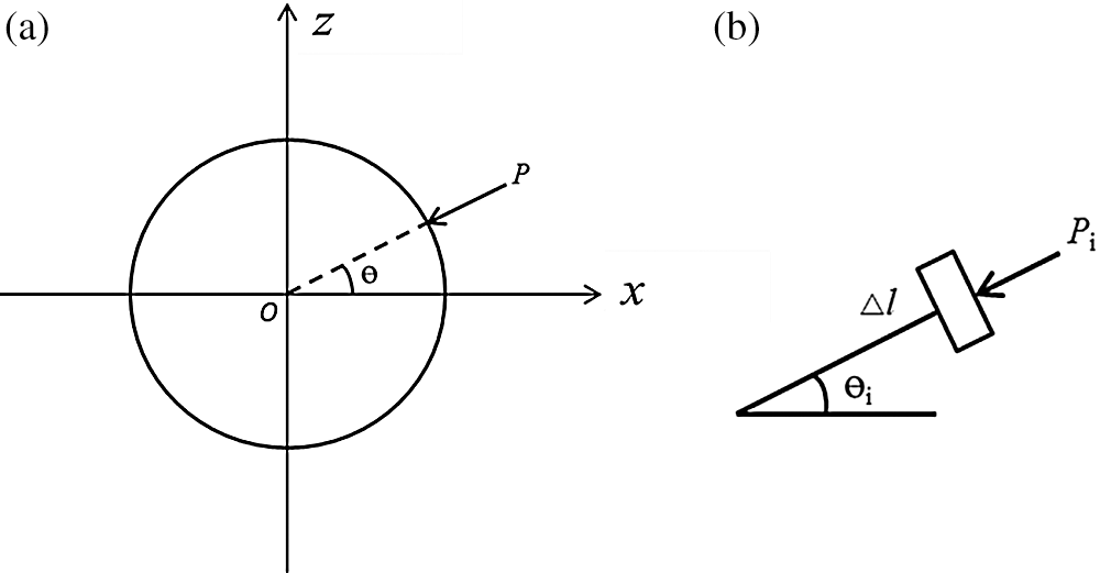
Figure 1: Calculation diagram of differential pressure resistance on circular cylinder
As shown in Fig. 2, P is the pressure on a certain point of the square cylinder edges at a depth y, and the horizontal differential pressure resistance on the square cylinder fs can be defined as:
where fsj is the pressure acting on the j-th side of the square cylinder, N , j = 1, 2, 3, 4, as shown in Fig. 2; Pi is the pressure of the i-th infinitesimal on each side of the square cylinder, N;
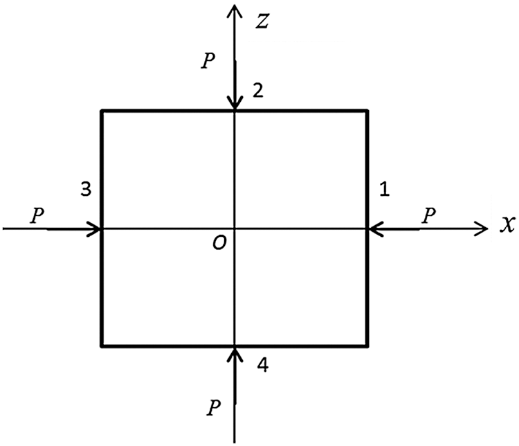
Figure 2: Calculation diagram of differential pressure resistance on square cylinder
As shown in Fig. 3, the tangential velocity
where ux and uz are the x-direction and z-direction velocity of the infinitesimal, cm/s; θ is the angle between the infinitesimal a and the X axis, (°), counterclockwise is positive. Then the viscous force
where
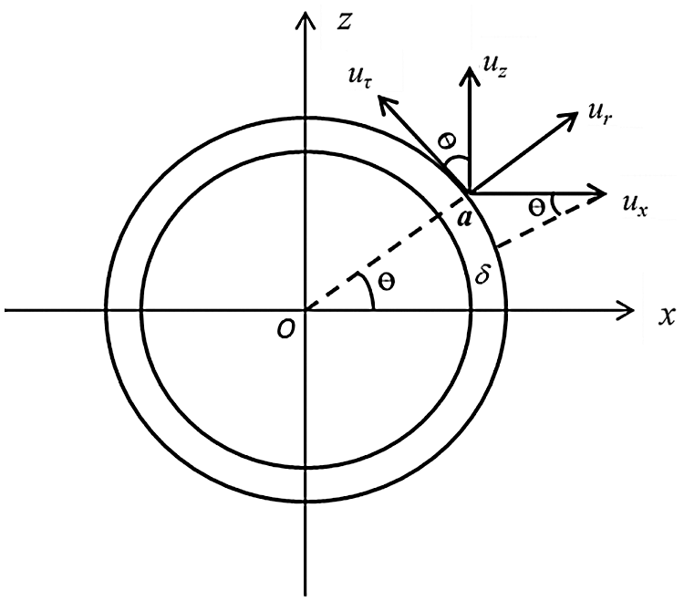
Figure 3: Calculation diagram of viscous force on circular cylinder
Based on the infinitesimal method, the horizontal viscous force on the circular cylinder
Following the calculation method of the viscous force on circular cylinder in Section 2.5.1, the viscous force
where
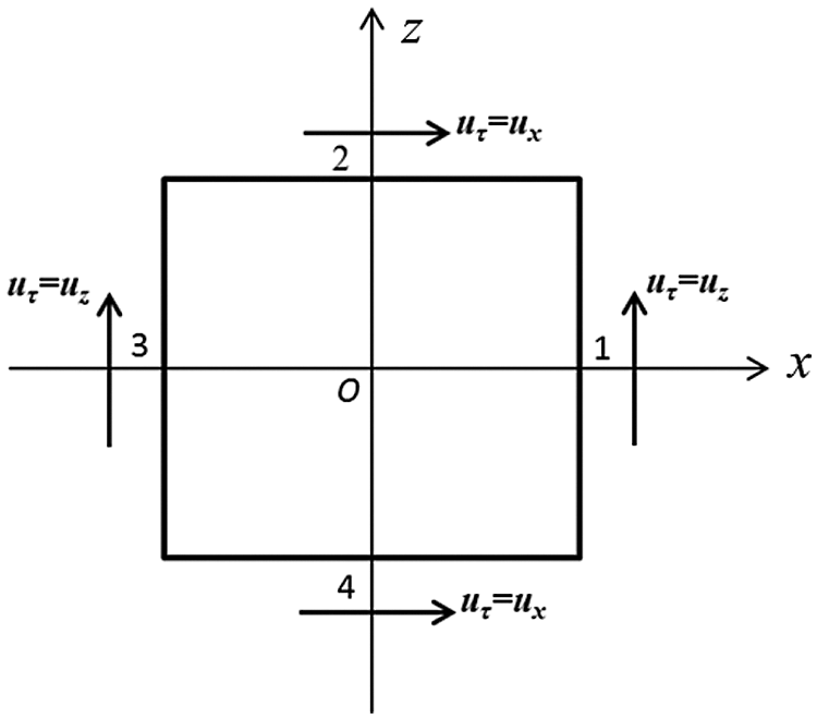
Figure 4: Calculation diagram of viscous force on square cylinder
A 3D numerical wave flume is developed in this study, as illustrated in Fig. 5, with a size of 12.0 m in length (X), 0.8 m in height (Y) and 0.6 m in width (Z). Schematic diagrams of the unstructured triangular mesh around the cylinder and the structured mesh of the tank in the vertical direction are shown in Figs. 6 and 7. The numbers of circumference nodes on the cylinder and vertical nodes along the tank are 60 and 85, respectively.
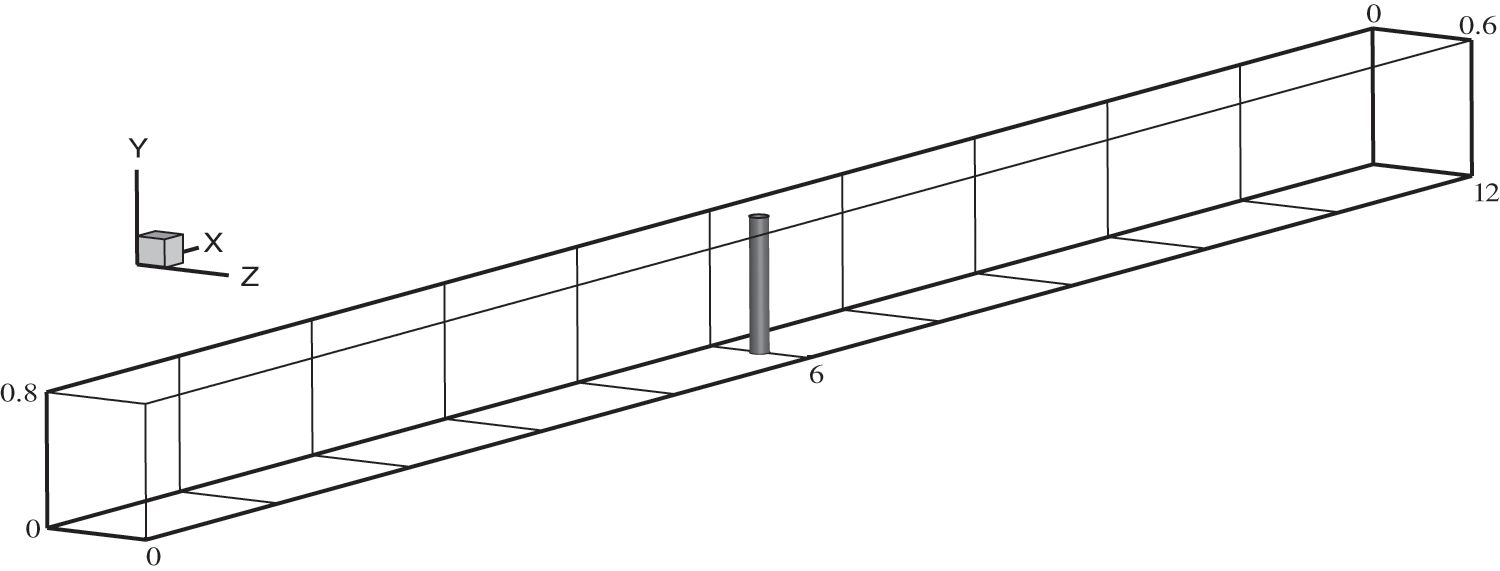
Figure 5: Schematic diagram of the 3D numerical flume, units: meters
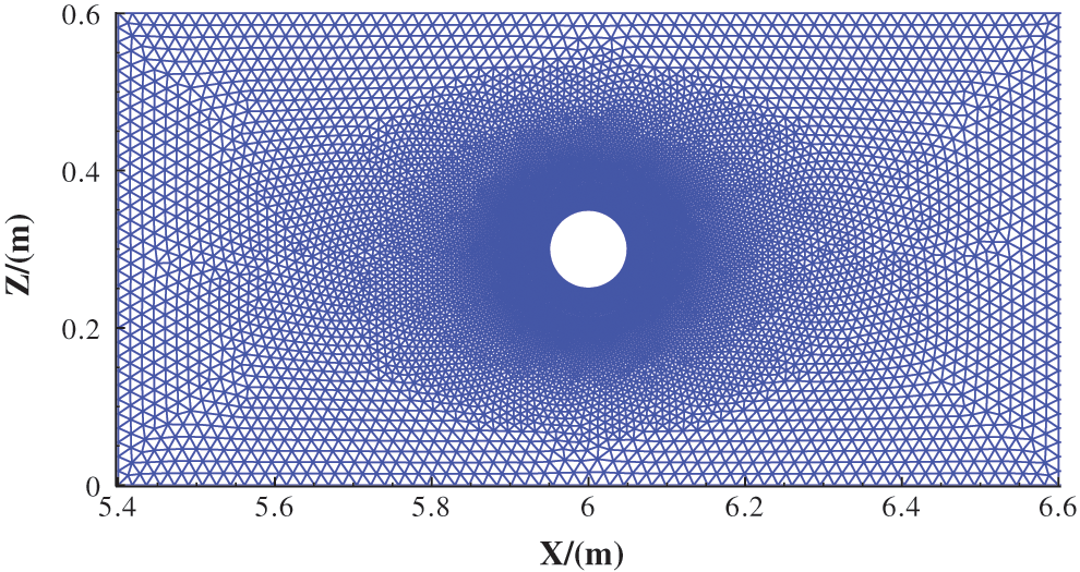
Figure 6: Close-up view of the triangular unstructured mesh around a cylinder
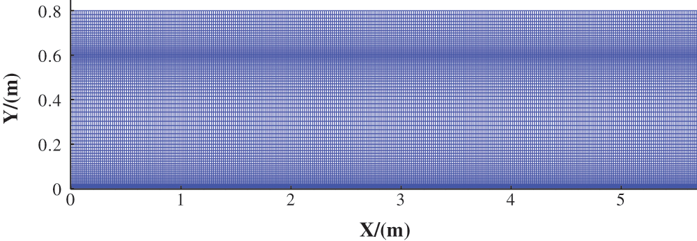
Figure 7: Close-up view of the structured mesh of the tank in vertical direction
In the current investigation, the dimensionless horizontal total force
where F is the total horizontal force on the circular cylinder and square cylinder calculated in the model, N; A is the windward area of the two types of cylinders, cm2; H is the total depth of the numerical flume, cm; and g is the gravitational acceleration, m/s2.
3.1 Cases and Parameters Setting
In current investigations, ISWs of depression type can be produced by a method of gravity collapse in a two-phase flow system [14]. The fluid densities of the upper layer and lower layers are ρ1 = 0.998 g/cm3 and ρ2 = 1.017 g/cm3, and the depths of the upper layer and lower layer are h1 = 0.2 m and h2 = 0.6 m, respectively. Consequently, H is equal to 0.8 m in this study. ηo/H represents the dimensionless wave amplitude when the ISW form is stable after propagating 4 m.
As illustrated in Fig. 8, the whole flume can be divided into a wave generation area and a wave propagation area. The former starts from the left boundary and is 0.7 m in length, and the latter is 11.3 m in length. ho, the height difference of the pycnocline between the two areas, and is called the step height, and the step length Lo, as called in this study is the generation area length.
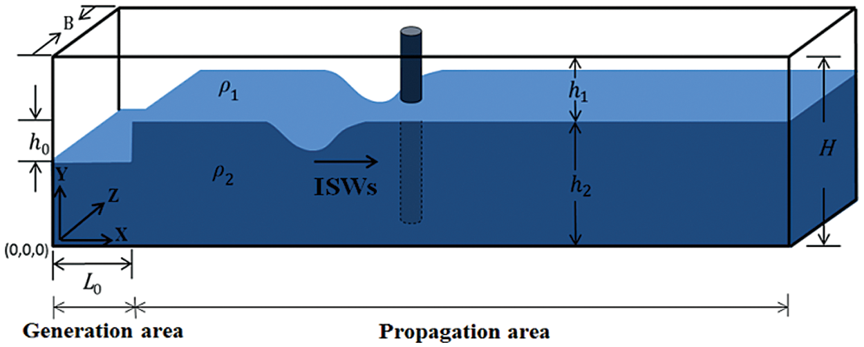
Figure 8: Schematic diagram of the gravity collapse to produce the ISWs in a two-phase flow system
3.2 Numerical Methods and Boundary Conditions
The generation and propagation of depression-type ISWs are simulated by a large-eddy simulation (LES) model. The governing equations are discretized by the finite-volume method [15]. The SIMPLE algorithm is applied to couple the velocity-pressure term and enforce mass conservation, and then the pressure field can be obtained [16,17]. A bounded central differencing scheme is adopted for solving momentum equation. The diffusion term is solved by the second-order central difference scheme, while the advection term is solved by the second order upwind scheme. The second-order implicit scheme is adopted to discretize the time step.
The left boundary, the two sidewalls, and the bottom of the wave flume are set to be rigid walls with no-slip conditions as illustrated in Fig. 9. To avoid wave reflection, the right boundary is specified by a “Sommerfeld radiation” type [18]. The top boundary is specified by the “rigid lid” approximation [19], because the surface waves are much smaller than the internal solitary waves [20,21]. Therefore, the “rigid lid” approximation is reasonable to use in the current research [22].
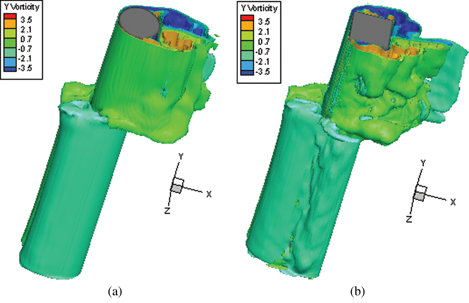
Figure 9: Instantaneous three-dimensional vorticity contours around cylinders, when F′ = F′max, ηo/H = 0.121 (a) Circular cylinder (b) Square cylinder
3.3 Numerical Model Verification
The validation of the established numerical model is executed by consulting the same procedure performed in reference [23]. The size of the tank, the meshing method and the boundary conditions used previously in reference [23] are chosen for the present numerical simulations.
4 Simulation Results and Analysis
The velocity field and pressure field in the ISW environment are different from those in the pure current environment, because the three-dimensional characteristics of the flow field induced by ISWs around a cylinder are more obvious as illustrated in Fig. 9. Instantaneous three-dimensional vorticity contours around cylinders clearly show that the vortex sheds in opposite directions in a stratified flow environment, and the vortex shedding from the square cylinder is more intense and erratic. Also, the flow structure and turbulence effect around the square cylinder has a stronger strength three-dimensional character than that around the circular cylinder.
The comparison of the instantaneous streamlines around the two types of cylinders at depths y = 0.3 m(Section P0.3) and y = 0.7 m (Section P0.7) is presented in Figs. 10a and 10b. The vortex around the square cylinder is more asymmetric and is larger in the recirculation zone, which could induce the more uneven pressure distribution on the cylinder.
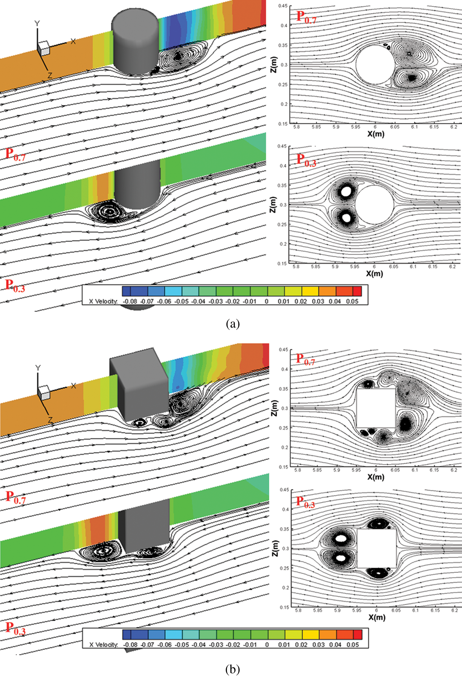
Figure 10: Instantaneous streamlines around cylinders on section P0.3 and P0.7, when F′ = F′max, ηo/H = 0.121 (a) Circular cylinder (b) Square cylinder
As a result, the ISW-induced force on the cylinder differs significantly from the force induced in a one-phase flow environment. Hence, it is of great significance to carry out research on the hydrodynamic characteristics around cylinders and the pressure distributions on them, which promotes the force behaviors for cylinders to be obtained in strong shear stratified environment.
4.1 Total Dimensionless Horizontal Force on a Cylinder
Based on the numerical simulation results, the trend curves of
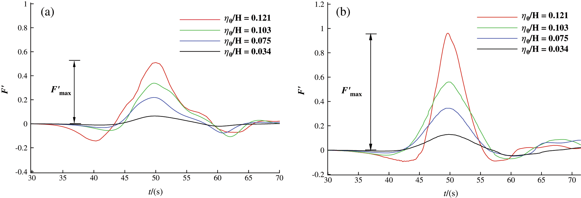
Figure 11: The trend curves of F′ with time t for different wave amplitudes
Meanwhile, it can be found that the propagation of ISWs is a transient motion. When passing through the cylinder, the ISW force on the cylinder is continuously changing. Therefore, the most unfavorable moment can be selected as the calculation feature time when
4.2 Differential Pressure Resistance and Viscous Force Distribution on the Cylinder along the Depth
The horizontal force on the cylinder can be divided into differential pressure resistance and viscous force.The basic ideas for solving these two kinds of forces are as follows: ① intercept a cross section at regular intervals on the cylinder along the vertical (Y) direction (9 sections in total), selecting 360 points along the circumference of each cross section. By extracting the pressure and velocity values at these points, the pressure and velocity distribution on circumference can be obtained; ② the infinitesimal method is adopted. By integrating the pressure and velocity distribution on circumferences at various depths, the differential pressure resistance f (Eqs. (14)–(15)) and viscous force fτ (Eqs. (19)–(20)) acting on the circular cylinder and square cylinder can be obtained respectively.
4.2.1 Differential Pressure Resistance
The dimensionless horizontal differential pressure resistance
Table 1: the dimensionless horizontal forces on circular and square cylinders, ηo/H = 0.121
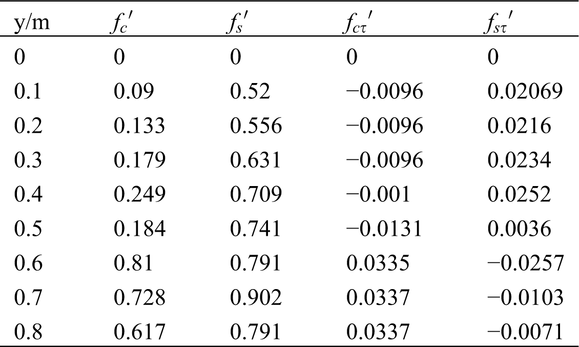
The dimensionless horizontal viscous force
The results show that the viscous force has little contribution to the total horizontal force on cylinders; therefore, the fluid viscosity effect can be ignored and only the effect of differential pressure resistance should be considered in the current study. This is similar to the result obtained under the condition of a pure flow environment: differential pressure resistance accounted for more than 95% of the total horizontal force [7], indicating that the viscosity effect is weak in both fluid environments.
4.3 Quantification Analysis of ISW Force on the Cylinder
Numerous studies have shown that forces on cylinders increase with increasing ISW amplitude [24]. In addition to the amplitude factor, the thicknesses of the upper layer h1 and lower layer h2 also determine the propagation characteristics of ISWs [25]. It can be inferred that the water depth ratio h1/h2 can also be a sensitivity parameter of the forces on cylinders. In this study, the influence rule of the relative amplitude ηo/H combined with h1/h2 on ISW forces is comprehensively considered, and the correlation between the maximum dimensionless horizontal force
Table 2: Cases and parameters setting of ISW force quantification analysis
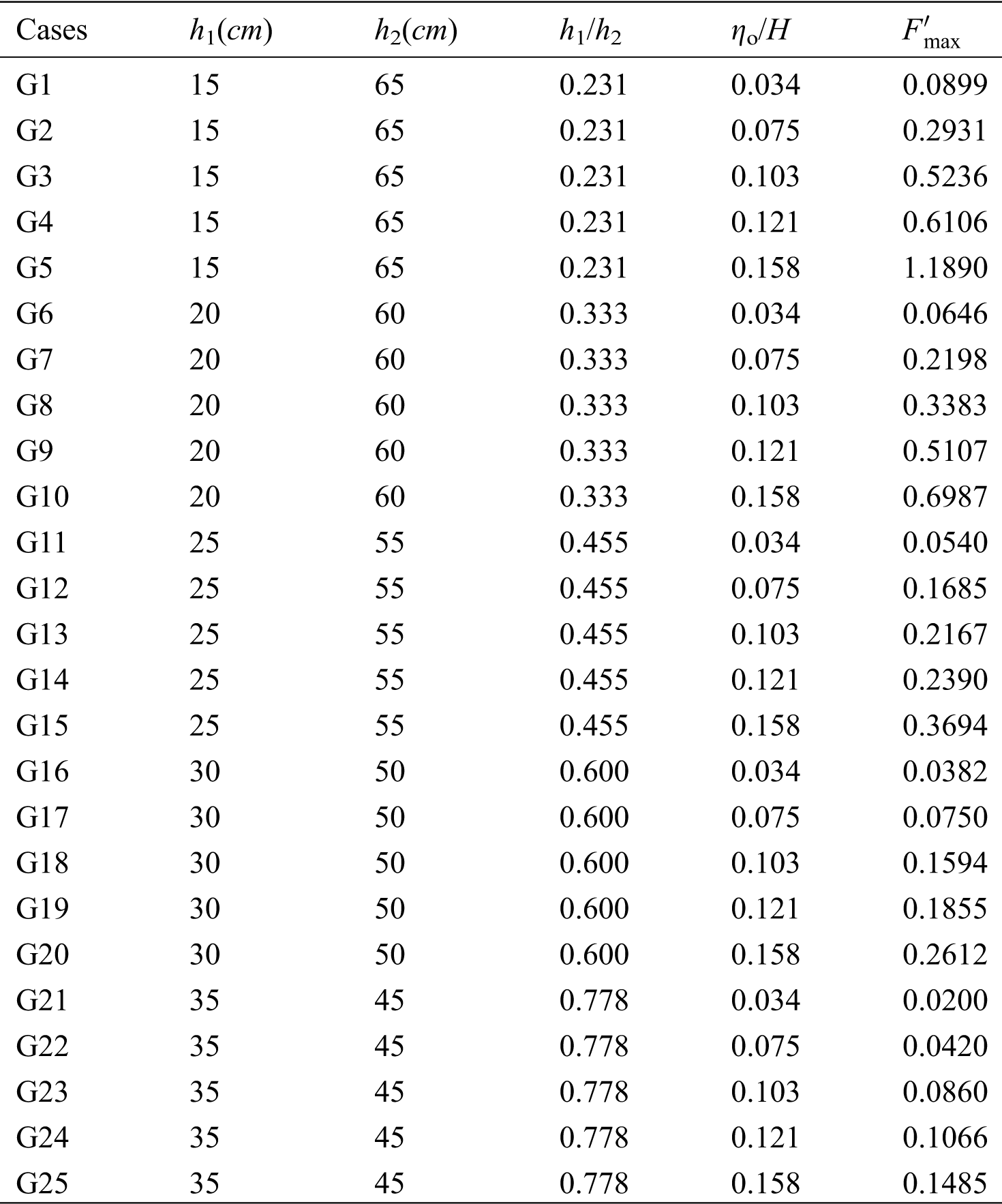
By analyzing the data in Tab. 2,
The goodness of fit R2 is only 0.3. Taking the calculated
By further logarithmically fitting the true value
R2 is fitted to be 0.957 with a high fitting degree at this time (as shown in Fig. 12). The comprehensive influence coefficient m has its own physical significance: The larger ηo/H and Δh = h1-h2 are, the larger the value of m and the forces on the cylinder are. m provides a quantitative index for the influence of ηo/H and h1/h2 on forces acting on the cylinder. Moreover, m is positively correlated with ηo/H and negatively correlated with h1/h2 (Eq. (25)). In summary, the forces on the cylinder increase with ηo/H under various stratification conditions; with the ISW of the same amplitude, the greater h1/h2 is, the smaller forces on the cylinder are.
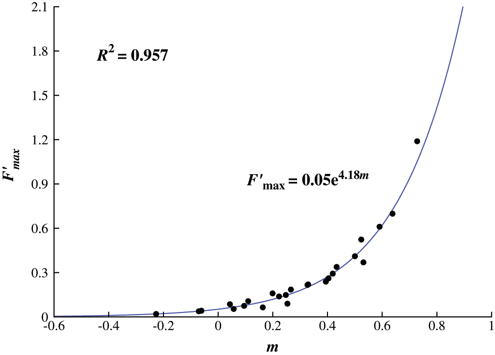
Figure 12: The correlation between F′max and m
A 3D numerical wave flume is used to meticulously study the ISW forces acting on cylinders through a large-eddy Simulation (LES) approach. By analyzing the hydrodynamic characteristics around cylinders and the pressure distributions on them, the detailed behaviors of differential pressure resistance and viscous force on cylinders can be obtained. The main conclusions from this study are as follows:
a) with the ISW of the same amplitude, the pressure difference resistance on the square cylinder in both the upper and lower layers is greater than that on the circular cylinder: the force on the square cylinder in the upper layer is approximately 1.5 times that on the circular cylinder, while the force on the square cylinder in the lower approximately is about 3.5 times that on the circular cylinder;
b) the viscous force acting on cylinders is 1-2 orders of magnitude smaller than the differential pressure resistance; therefore, the effect of fluid viscosity can be ignored and only the effect of differential pressure resistance should be considered;
c) the maximum dimensionless ISW horizontal force
Acknowledgement: We gratefully acknowledge the valuable cooperation of Prof. Lingling Wang and the members of her laboratory in preparing this Application note .
Funding Statement: This work was supported by the Jiangxi Natural Science Foundation of China [Grant No. 20202BABL214050]; and the Sci-tech Program by Jiangxi Provincial Education Department of China [Grant No. GJJ190942].
Conflicts of Interest: The authors declare that they have no conflicts of interest to report regarding the present study.
1. Kurkina, O., Rouvinskaya, E., Talipova, T., Soomere, T. (2017). Propagation regimes and populations of internal waves in the Mediterranean Sea basin. Estuarine, Coastal and Shelf Science, 185(C3), 44–54. DOI 10.1016/j.ecss.2016.12.003. [Google Scholar] [CrossRef]
2. Colosi, J. A., Kumar, N., Suanda, S. H., Freismuth, T. M., Macmahan, J. H. (2018). Statistics of internal tide bores and internal solitary waves observed on the inner continental shelf off point sal, California. Journal of Physical Oceanography, 48(19), 123–143. DOI 10.1175/JPO-D-17-0045.1. [Google Scholar] [CrossRef]
3. Yang, F., Zhu, R. Q., Chen, X. D., Wei, J. R., Liu, X. (2017). Numerical simulation for the load of internal solitary waves acting on a submerged body. Ship Science and Technology, 39(9), 26–31 (in Chinese). [Google Scholar]
4. Wang, X., Zhou, J. F., Wang, Z., You, Y. X. (2018). A numerical and experimental study of internal solitary wave loads on semi-submersible platforms. Ocean Engineering, 150(12), 298–308. DOI 10.1016/j.oceaneng.2017.12.042. [Google Scholar] [CrossRef]
5. Cai, S. Q., Long, X., Wang, S. (2008). Forces and torques exerted by internal solitons in shear flows on cylindrical piles. Applied Ocean Research, 30(1), 72–77. DOI 10.1016/j.apor.2008.03.001. [Google Scholar] [CrossRef]
6. Xu, W., Lin, Z. Y., You, Y. X., Yu, R. (2017). Numerical simulations for the load characteristics of internal solitary waves on a vertical cylinder. Journal of Ship Mechanics, 21(9), 1071–1085. [Google Scholar]
7. Redchyts, D. O., Shkvar, E. A., Moiseienko, S. V. (2019). Control of karman vortex street by using plasma actuators. Fluid Dynamics & Materials Processing, 15(5), 509–525. DOI 10.32604/fdmp.2019.08266. [Google Scholar] [CrossRef]
8. Xie, J., Xu, J. C., Cai, S. Q. (2011). A numerical study of the load on cylindrical piles exerted by internal solitary waves. Journal of Fluids and Structures, 27(8), 1252–1261. DOI 10.1016/j.jfluidstructs.2011.04.007. [Google Scholar] [CrossRef]
9. Si, Z. J., Zhang, Y. L., Fan, Z. S. (2012). A numerical simulation of shear forces and torques exerted by large-amplitude internal solitary waves on a rigid pile in South China Sea. Applied Ocean Research, 37(4), 127–132. DOI 10.1016/j.apor.2012.05.002. [Google Scholar] [CrossRef]
10. Cai, S. Q., Xu, J. C., Chen, Z. (2014). The effect of a seasonal stratification variation on the load exerted by internal solitary waves on a cylindrical pile. Acta Oceanologica Sinica, 33(7), 21–26. DOI 10.1007/s13131-014-0468-8. [Google Scholar] [CrossRef]
11. Redchyts, D. O., Shkvar, E. A., Moiseienko, S. V. (2019). Computational simulation of turbulent flow around tractor-trailers. Fluid Dynamics and Materials Processing, 15(5), 509–525. DOI 10.32604/fdmp.2019.08266. [Google Scholar] [CrossRef]
12. Germano, M., Piomelli, U., Moin, P., Cabot, W. H. (1991). A dynamic subgrid-scale eddy viscosity model. Physics of Fluids A: Fluid Dynamics, 3(7), 1760–1765. DOI 10.1063/1.857955. [Google Scholar] [CrossRef]
13. Wei, G., Du, H., Xu, X. H., Zhang, Y. M., Qu, Z. Y. et al. (2014). Experimental investigation of the generation of large-amplitude internal solitary wave and its interaction with a submerged slender body. Science China Physics, Mechanics & Astronomy, 57(2), 301–310. DOI 10.1007/s11433-013-5196-0. [Google Scholar] [CrossRef]
14. Hsieh, C. M., Hwang, R. R., Hsu, R. C., Cheng, M. H. (2014). Flow evolution of an internal solitary wave generated by gravity collapse. Applied Ocean Research, 48, 277–291. DOI 10.1016/j.apor.2014.10.001. [Google Scholar] [CrossRef]
15. Chekifi, T. (2019). Droplet breakup regime in a cross-junction device with lateral obstacles. Fluid Dynamics & Materials Processing, 15(5), 545–555. DOI 10.32604/fdmp.2019.01793. [Google Scholar] [CrossRef]
16. Yu, Z. Z., Wang, L. L. (2011). Factors influencing thermal structure in a tributary bay of three gorges reservoir. Journal of Hydrodynamics, 23(4), 407–415. DOI 10.1016/S1001-6058(10)60130-8. [Google Scholar] [CrossRef]
17. Kozelkov, A. S., Lashkin, S. V., Kurkin, A. A., Kornev, A. V., Vyalykh, A. M. (2020). An efficient parallel implementation of the SIMPLE algorithm based on a multigrid method. Numerical Analysis and Applications, 13(1), 1–16. DOI 10.1134/S1995423920010012. [Google Scholar] [CrossRef]
18. Ferziger, J. H., Milova, P. (2002). Computational methods for fluids dynamics. Berlin Heidelberg: Springer. [Google Scholar]
19. Zhu, H., Wang, L. L., Tang, H. W. (2014). Large-eddy simulation of the generation and propagation of internal solitary waves. Science China, 57(6), 1128–1136. [Google Scholar]
20. Zhu, H., Wang, L. L., Avital, E. J., Tang, H. W., Williams, J. J. R. (2017). Numerical simulation of shoaling broad-crested internal solitary waves. Journal of Hydraulic Engineering, 143(6), 04017006 1–04017006 16. DOI 10.1061/(ASCE)HY.1943-7900.0001278. [Google Scholar] [CrossRef]
21. Zhu, H., Wang, L. L., Avital, E. J., Tang, H. W., Williams, J. J. R. (2016). Numerical simulation of interaction between internal solitary waves and submerged ridges. Applied Ocean Research, 58(5), 118–134. DOI 10.1016/j.apor.2016.03.017. [Google Scholar] [CrossRef]
22. Aghsaee, P., Boegman, L., Lamb, K. G. (2010). Breaking of shoaling internal solitary waves. Journal of Fluid Mechanics, 659(659), 289–317. DOI 10.1017/S002211201000248X. [Google Scholar] [CrossRef]
23. Wang, L. L., Xu, J., Wang, Y., Wei, G., Lin, C. et al. (2018). Reduction of internal-solitary-wave-induced forces on a circular cylinder with a splitter plate. Journal of Fluids and Structures, 83(4), 119–132. DOI 10.1016/j.jfluidstructs.2018.08.015. [Google Scholar] [CrossRef]
24. Wang, Y., Wang, L. L., Zhu, H., Wei, G., Tang, H. W. (2016). A numerical study of the forces on two tandem cylinders exerted by internal solitary waves. Mathematical Problems in Engineering, 2016(1), 1–15. DOI 10.1155/2016/9086246. [Google Scholar] [CrossRef]
25. Xie, H. R., Xiong, X. J., Chen, L. (2019). Calculation of the maximal force exerted by internal solitary waves on piles in slope area of the northern South China Sea. Advances in Marine Science, 37(2), 171–186. [Google Scholar]
 | This work is licensed under a Creative Commons Attribution 4.0 International License, which permits unrestricted use, distribution, and reproduction in any medium, provided the original work is properly cited. |