Materials Processing
| Fluid Dynamics & Materials Processing |
DOI: 10.32604/fdmp.2021.014762
ARTICLE
Analysis of the Flow Field Characteristics Associated with the Dynamic Rock Breaking Process Induced by a Multi-Hole Combined External Rotary Bit
1State key Laboratory of Gas Disaster Monitoring and Emergency Technology, Chongqing, 400037, China
2CCTEG Chongqing Research Institute, Chongqing, 400037, China
*Corresponding Author: Yanbao Liu. Email: yanbao_liu@163.com
Received: 27 October 2020; Accepted: 12 March 2021
Abstract: The characteristics of the flow field associated with a multi-hole combined external rotary bit have been studied by means of numerical simulation in the framework of an RNG k-ε turbulence model, and compared with the results of dedicated rock breaking drilling experiments. The numerical results show that the nozzle velocity and dynamic pressure of the nozzle decrease with an increase in the jet distance, and the axial velocity of the nozzle decays regularly with an increase in the dimensionless jet distance. Moreover, the axial velocity related to the nozzle with inclination angle 20° and 30° can produce a higher hole depth, while the radial velocity of the nozzle with 60° inclination can enlarge the hole diameter. The outcomes of the CFD simulations are consistent with the actual dynamic rock breaking and pore forming process, which lends credence to the present results and indicates that they could be used as a reference for the future optimization of systems based on the multi-hole combined external rotary bit technology.
Keywords: External rotation nozzle; RNG k-ε turbulence model; flow field characteristics; rock breaking and hole forming; process analysis
Nomenclature
| Ρ : | Density of fluid |
| t : | Time |
| u, v, w : | Components of velocity |
| x, y, z : | Directions |
| μ : | Dynamic viscosity coefficient |
| σk : | Reciprocal of the effective turbulent Prandtl number |
| k : | Kinetic energy |
| σε : | Reciprocal of the effective turbulent Prandtl number |
| ε : | Dissipation rate |
| | Transient energy under controlled volume conditions |
| | Convection item |
| | Diffusion item |
| | Original item |
Hydraulic jet radial drilling technology finds its roots in ultra-short radius radial horizontal wells in oil and gas drilling industry [1–3]. The technology can be used to drill one or more branch holes in different coal strata of the same main drill hole to effectively increase the exposed area of coal seam, link coal seam fissures, increase drilling distance, reduce drilling engineering quantity and cost, and improve coal seam gas permeability and coalbed methane production [4].
The hydraulic jet drilling nozzle has undergone the development from the initial single-hole and multi-hole direct-injection type to the single-hole internal rotation type and multi-hole internal rotation type, and the rock breaking efficiency is gradually improved. The underground working conditions in coal mine entails small size of nozzle and large spray distance, wide range of action, high rock breaking efficiency and good hole-forming effect. In addition, the gradual increase of mining depth has posed higher demands for drilling hole-forming effect, so the structural parameters of hydraulic jet drilling nozzle and rock-breaking hole-forming effect need further optimization and improvement.
Liao et al. [5] proposed a new type of nozzle design simulated using RNG k-ε turbulent model which compared by the use of high-speed photography, and the results show that the jet by the new designed nozzle has both features of round straight jet and swirling jet. Song et al. [6] used the three-dimensional N-S equation and the standard two-equation turbulence model to calculate the turbulence information of the flow field. Du [7] used the RNG turbulence model to analyze the flow field structure of the swirling mixed jet, and optimized the internal swirl design through numerical simulation, and used high-speed photography to compare the jet structure with rock breaking characteristics. Liao et al. [8] conducted for 6 type of multi-orifice nozzles on water jet breaking rock, and the factors were analyzed with the rock breaking effect including numbers of nozzle orifices, hydraulic parameters such as erosion time, nozzle pressure drop, spray distance and confining pressure value. Ma et al. [9] used self-designed jet rock braking system, conducted the experiments on erosion time, impact pressure, confining pressure, standoff distance, numbers of nozzle orifices and lateral orifice angle. Xiao et al. [10] established the three-dimension drilling model of the self-rotatory water-jet bit, and conducted the numerical simulation to improve the drilling performance, the effects of the standoff distance, bit rotation speed, and nozzle layout parameters on the self-rotatory water-jet bit drilling capability. Due to the restrictions of underground coal mine operation conditions, the bit size requirements are small, and the spraying distance is large, the action range is wide, the rock breaking efficiency is high, and the hole-forming effect is good. In addition, with coal mines gradually moving toward deep mining, higher requirements are put forward for the effect of drilling and hole formation [11,12], so the structural parameters of the hydraulic jet drilling nozzle and the effect of rock breaking and hole formation need to be optimized.
Therefore, based on the requirements of hole-forming depth and diameter in the radial drilling process, this paper studies the flow field characteristics of the multi-hole combined external rotation nozzle using numerical simulation and laboratory test methods, RNG k-ε turbulence model and SIMPLE algorithm. Through the comparative analysis of the simulation results of flow field characteristics and the actual dynamic rock-breaking hole-forming process, this paper provides a reference for the optimization of the structure and parameters of hydraulic jet radial drilling nozzle.
2.1 Structure of Multi-Hole Combined External Rotation Nozzle
Hydraulic jet drilling nozzle is a key component of radial drilling technology. It requires large jet impact area, high rock-breaking hole-forming efficiency and low power consumption, and requires that the size of the nozzle is reduced as much as possible to achieve steering on the basis of ensuring the jet performance. I recent years, the improvement of manufacturing technology and the research progress of clearance seal mode has made the miniaturization of external rotation nozzle possible. The multi-hole combined external rotation nozzle is mainly composed of a shell, a rotating body, a rotating shaft, a forward nozzle and a reverse nozzle [13]. The structure of the nozzle is shown in Fig. 1. The rotating body is the core component of the external rotation nozzle, which is connected with the main body of the nozzle through the rotary shaft and shell, and the clearance seal is used to achieve dynamic sealing effect, that is, to realize the liquid rotary seal under the condition that a certain amount of leakage is allowed in order to achieve the purpose of reducing the size [14,15]. A number of nozzles are arranged at the front end of the rotating body, which are mainly forward nozzles and reverse nozzles, and each nozzle forms different angles along the axial direction of the nozzle. In the process of drilling, the forward nozzle realizes rock-breaking drilling, the reverse nozzle provides forward power, and the rock debris are discharged from the bottom of the hole, and the nozzle deflection angle and torque realize the nozzle rotation.
Figure 1: The structure of multi-hole combined external rotation nozzle
High pressure water jet is a complex unsteady flow. In jet flow, various physical parameters of fluid, such as velocity and pressure change randomly with time and space. However, it is generally believed that the unsteady N-S equation is still applicable to the instantaneous motion of turbulent flow no matter how complex the turbulent motion is. The governing equation of incompressible flow is as follows:
(1) Conservation equation of mass
where, u, v and w are the components of velocity in the x, y and z directions, respectively.
(2) Momentum conservation equation
where, ρ is density of fluid; μ is the dynamic viscosity.
(3) Turbulence model
In this paper, the drilling bit is composed of multiple nozzles. The internal watershed structure is relatively complicated. The fluid is easy to form a vortex at the corner of the nozzle. It is more complicated than the common jet. Therefore, the reflow group
Standard
RNG
where,
(4) Equation discretization
A finite volume method (controlled volume method) is used to establish a discrete equation for fluid motion. For incompressible fluid, the governing equation of the three-dimensional jet is as follows:
where
The general conservation equation is as follows:
where
(5) Algorithm
The SIMPLE algorithm used in this paper is mainly applied to the numerical calculation of incompressible flow fields. For a given pressure field, the discrete momentum equation is solved to obtain the velocity field. The second order upwind scheme is adopted in this paper [16].
2.3 Building Model and Boundary Conditions
As shown in Fig. 2, CFD numerical simulation generally follows the following five steps [17]:
1. Establish a physical model of the research problem, and then abstract it into a mathematical and mechanical model. Then determine the spatial influence area of the geometry to be analyzed.
2. Establish the entire geometric body and its spatial influence area, and divide the outer surface of the geometric body and the entire calculation area into a spatial mesh. The sparseness of the grid and the shape of the grid cells will have a great impact on future calculations. In order to ensure the stability and efficiency of calculation, different algorithm formats generally have different requirements on the grid.
3. Add the initial conditions required for the solution, and the boundary conditions at the inlet and outlet are generally speed and pressure conditions.
4. Select the appropriate algorithm, set the specific control solution process and accuracy conditions, solve the problem to be analyzed, and save the data file results.
5. Select the appropriate post processor (Post Processor) to read the calculation result file, analyze and display it.
Figure 2: Calculation flow chart
Based on the study of jet characteristics under submerged conditions during the drilling process of the multi-hole combined external rotation nozzle, the three-dimensional model of the external rotation nozzle is simplified, and the structural models of the nozzle rotating body, internal flow channel and nozzle are extracted, as shown in Fig. 3. First, an external submerged environment is built. The cylinder has a diameter of 40 mm and a height of 30 mm; the internal flow channel has a diameter of 3.5 mm. Three nozzles are arranged in the front and two nozzles are arranged in the rear. The forward nozzle diameter is 0.5 mm, and the reverse nozzle diameter is 0.8 mm. The nozzle inclination angle is 20°, 30°, 60°, and the reverse nozzle inclination angle is 50°; the center surface of the rear end is selected as the pressure inlet, the edge surface of the rear end is selected as the pressure outlet, and the side of the cylinder is selected as the wall surface.
Figure 3: Geometric model of multi-hole combined external rotation nozzle
2.3.2 Meshing and Boundary Conditions
Due to the complexity of most calculation areas in practical engineering calculation, the final accuracy of CFD calculation results and the efficiency of calculation process mainly depend on the grid generated and the algorithm adopted [18]. The grid used in CFD calculation can be roughly divided into structured grid and unstructured grid. Considering the complexity of the project model, unstructured grid is adopted. The connection between the nodes of the unstructured grid is disordered and irregular, and the position of the nodes of the unstructured grid cannot be named orderly by a fixed rule. Compared with structured grid, unstructured grid has the following advantages:
1. It can discretion areas with complex shapes, because unstructured grid cells can completely fill the entire space in any calculation area, and can represent the boundary of the object fairly accurately, thereby ensuring the initial accuracy of the boundary.
2. It can quickly add and delete nodes in the grid, and it is more convenient to cope with moving boundary problems.
3. The adaptive grid method can be easily adopted to improve the quality of the solution.
In this numerical simulation, the physical model is divided into two parts: tetrahedron mesh generation method is adopted in the calculation domain, and mesh densification measures are taken for the parts with severe velocity gradient change, so as to ensure the stability of the calculation process and the correctness of the calculation results. In order to simulate the process boundary to have better simulation effect, the boundary layer is set, the thickness of boundary layer is 0.00002. The number of grids reached 880000, As shown in Fig. 4.
Figure 4: Grid division and boundary conditions of external rotation nozzle ((a) Inundated area grid; (b) Nozzle watershed grid)
Inlet boundary: Pressure inlet boundary condition: the pressure inlet boundary condition is usually used to give the pressure of fluid inlet and other scalar parameters of flow, which is suitable for calculating compressible and incompressible problems. The pressure inlet boundary condition is usually used for the flow without knowing the inlet flow rate or flow velocity. This kind of flow is common in engineering, such as buoyancy driven flow problem. The pressure inlet condition can also be used to deal with the free boundary of external or unrestricted flow. The pressure inlet boundary is adopted at the inlet, and the pressure inlets of 20 MPa, 40 MPa, 60 MPa and 80 MPa are used in the simulation.
Outlet boundary: Pressure outlet boundary condition: the outlet static pressure (gauge pressure) needs to be given. Moreover, the pressure is only used for subsonic calculation (m < 1). If the local velocity becomes supersonic, the boundary conditions are deduced according to the previous inflow conditions. It should be noted that the pressure here is relative to the working pressure given above. Given atmospheric pressure at the outlet, 0.1 MPa.
Wall condition: For viscous flow problems, the default setting of FLUENT is without sliding. All the walls are fixed without sliding.
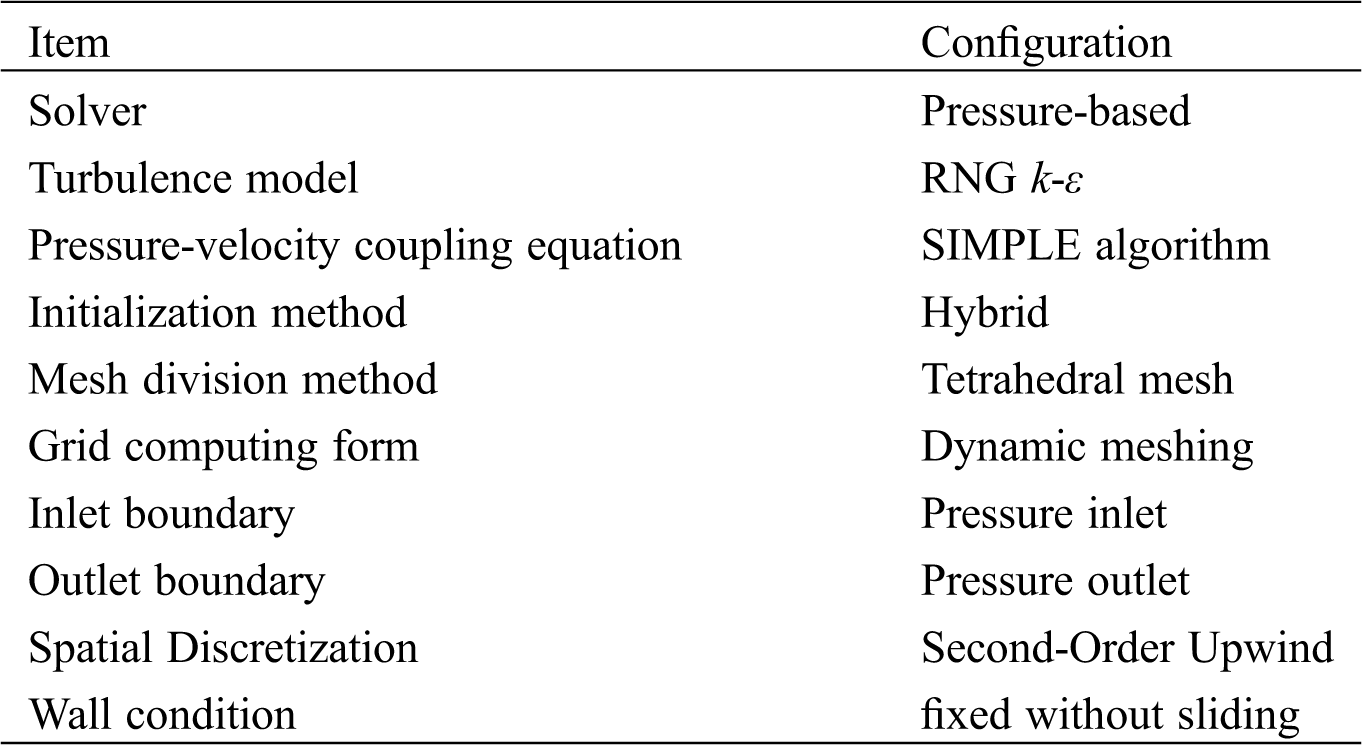
In this paper, steady state calculations are used first, and when convergence is reached, transient calculations are performed. The steady state convergence condition is that the Equation Residual is below 0.001. Set the number of iterations to 10000 in the steady state. The transient calculation time step size is 0.001, and the number of time steps 3000. The main numerical simulation settings and boundary conditions as shown Tab. 1.
Table 1: Numerical simulation method
3 Numerical Simulation Results and Discussions
Fig. 5 is the jet velocity cloud picture of the forward nozzle of the external rotation nozzle showing the actual jet situation of each nozzle in the forward direction. The jets of 20° and 30° nozzles are on the same side, and the jets can influence one another, and the range where they influence each other is the overlap area of the crushing impact; the jet of 60° nozzle is on the other side, and the jet is less affected and keeps independent striking characteristics. The tangential velocity of the jet of the external rotation nozzle is relatively small and is provided by the rotation of the nozzle. Therefore, when the nozzle rotates, the 20° and 30° nozzles can rotate in a combined form to scan the wall surface, and the 60° nozzle jet impacts the wall through reaming; as the opening angle of the nozzle increases, the wall attachment effect of the jet in the hole is more obvious, and the energy loss is also greater.
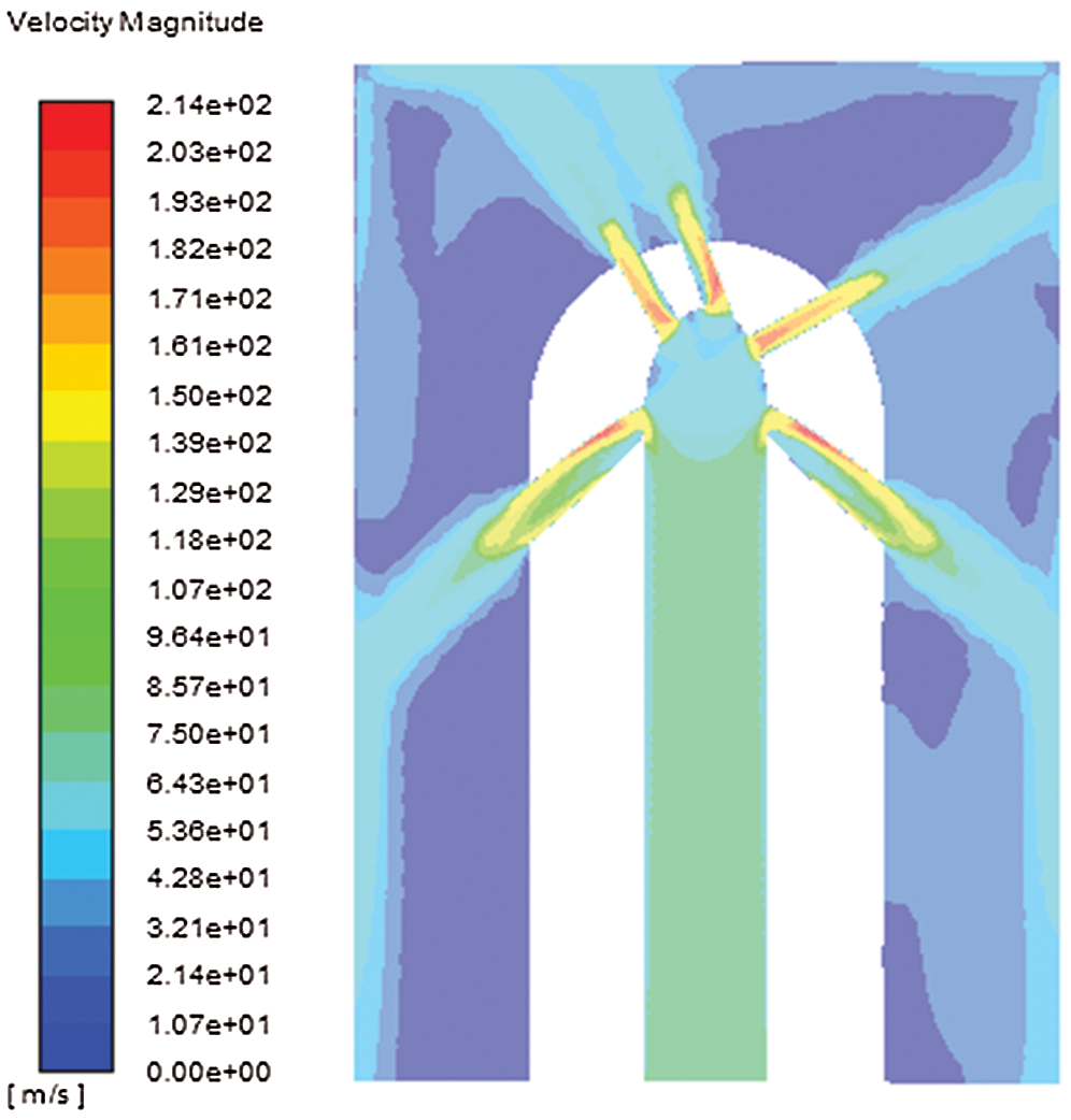
Figure 5: Velocity cloud picture of flow field of external rotation nozzle
3.1 Variation of Velocity Distribution of Nozzles in Different Directions
Fig. 6 shows the variation curve of the axial velocity distribution of the 20°, 30°, and 60° nozzles of the external rotation nozzle. The figure shows that the 20° and 30° nozzles attenuate rapidly in the range of dimensionless spray distance (the ratio of the spray distance to the nozzle diameter) of 0~3, and attenuate more slowly in the range of dimensionless spray distance of 3~12; the axial velocity and radial velocity of the 60° nozzle attenuate rapidly in the dimensionless spray distance of 0~1, and attenuate slowly in the range of 1~5. In addition, the axial velocity of the 20° and 30° nozzles is greater than the radial velocity, and the attenuation is slow, which can provide greater impact force to crush coal and rock; the radial velocity of the 60° nozzle is greater than the axial velocity, and the 60° nozzle crushes coal and rock mainly through shear force.
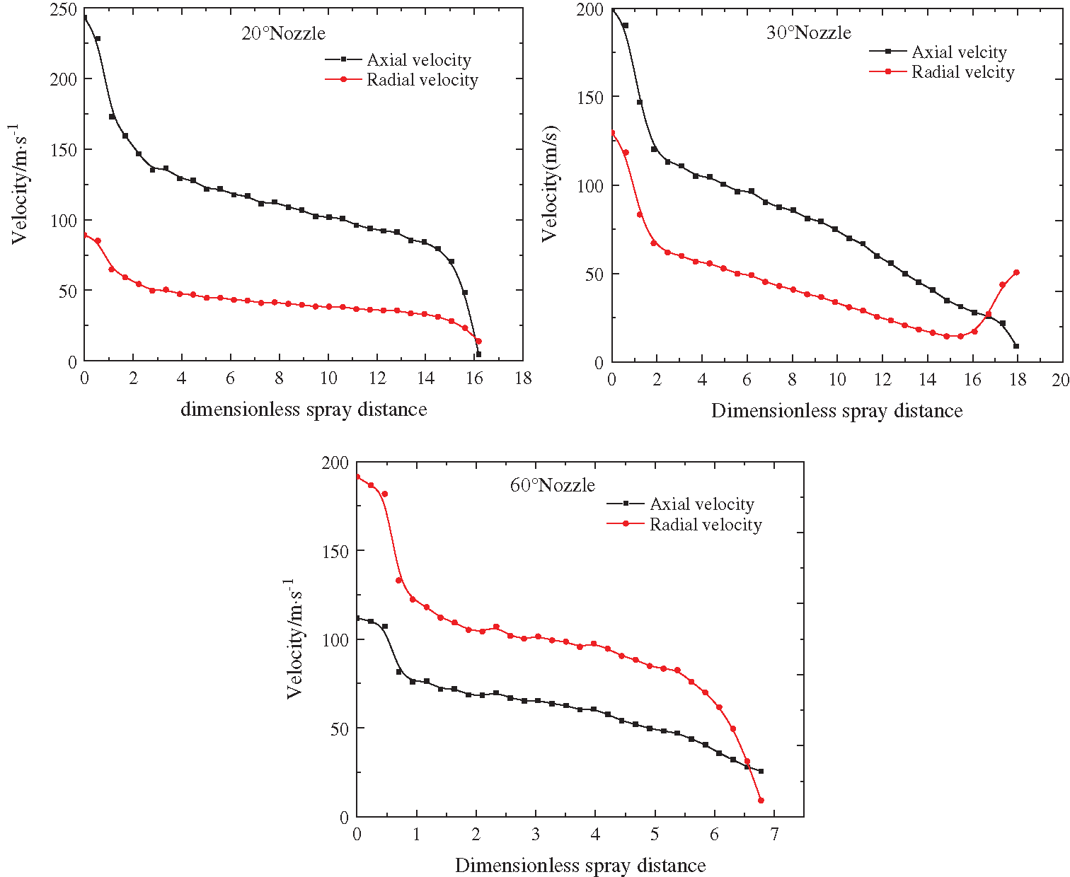
Figure 6: The velocity variation curve of the multi-hole combined external rotation nozzle
3.2 Variation of Pressure Distribution in Different Spray Distances
Fig. 7 shows that the transverse radius range of the jet pressure of the forward nozzle shows a peak distribution under different spray distances, and each peak point corresponds to the corresponding jet direction of the nozzle. There is a low pressure area between the two nozzles, and the jet pressure of the 20° nozzle is higher than that of the 30° nozzle. It can be seen from the picture that, due to the expansion angle of the nozzle, the jet pressure is reaching the peak point with the increase of the spray distance. At the 0.5 mm spray distance, the pressure is negative, which is due to the close distance between the 20° and 30° nozzles and the negative pressure caused by the phase flow of high pressure and high velocity jets. The dynamic pressure attenuation at the spray distance of 0.5 mm and 1.0 mm is not obvious, but the dynamic pressure attenuation is rapid when the injection distance is from 2 mm to 4 mm. With the increase of the spray distance, the transverse radius corresponding to the peak point increases, the jet divergence angle increases gradually, and the jet area expands gradually within the effective spray distance.
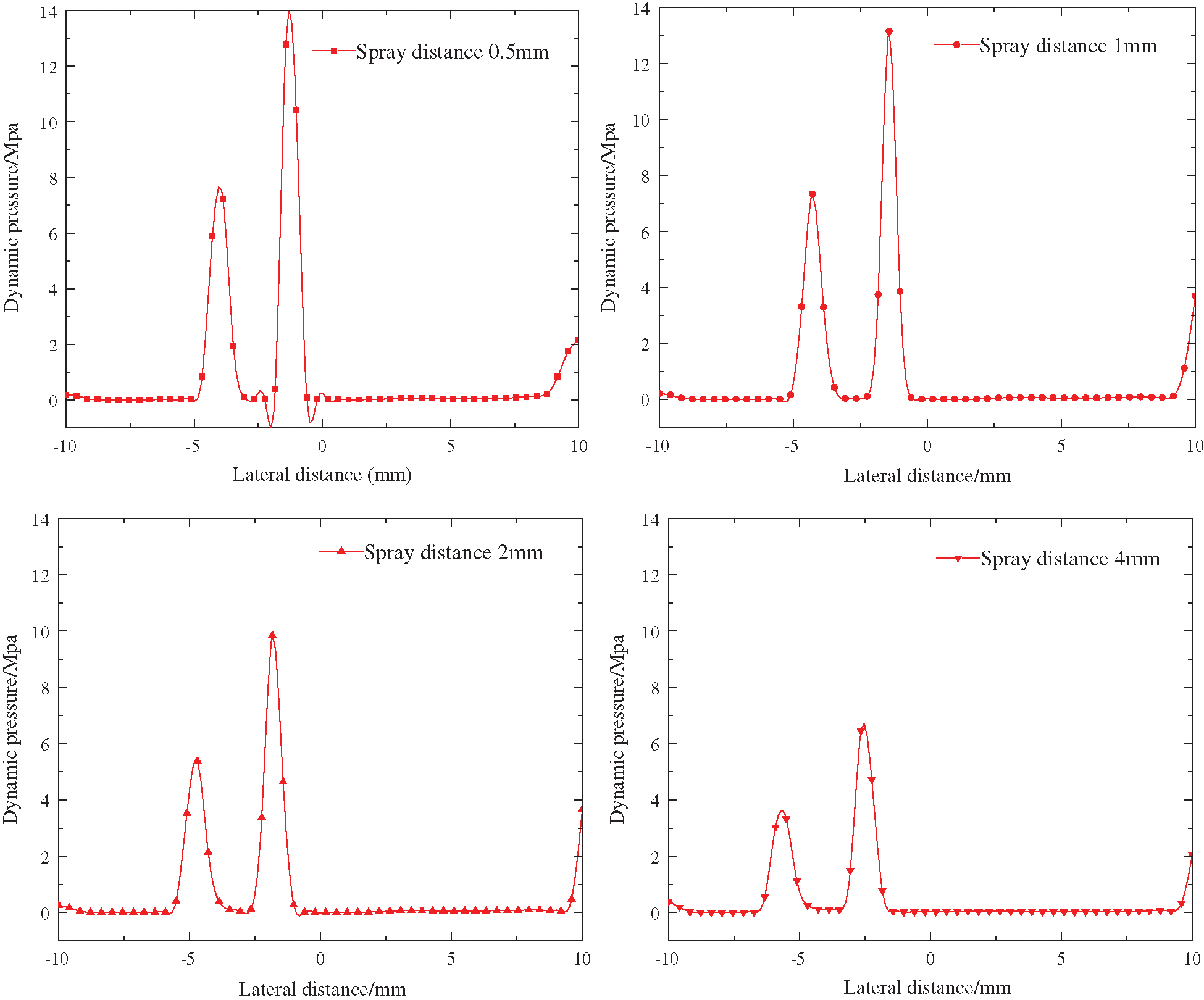
Figure 7: Pressure change curve in different spray distance
3.3 Variation of Velocity Distribution in Different Spray Distances
Fig. 8 shows the velocity variation curve of external rotation nozzles at different spray distances. It can be seen from the figure that the cross-sectional velocities under different spray distances show two groups of peak points, the first peak point corresponds to 20° nozzle axis velocity, and the second peak point corresponds to 30° nozzle axis velocity. Within the range of 0.5 mm~4.0 mm spray distance, the axial velocity of the nozzle decreases stepwise with the increase of the spray distance, and the velocity of the 20° nozzle is about 40 m/s higher than that of the 30° nozzle; with the increase of the spray distance, the peak point of velocity slowly deviates from the axis of the nozzle, the distance between the peak points increases gradually with the increase of the spray distance, and the jet area of the nozzle expands with the increase of the spray distance.
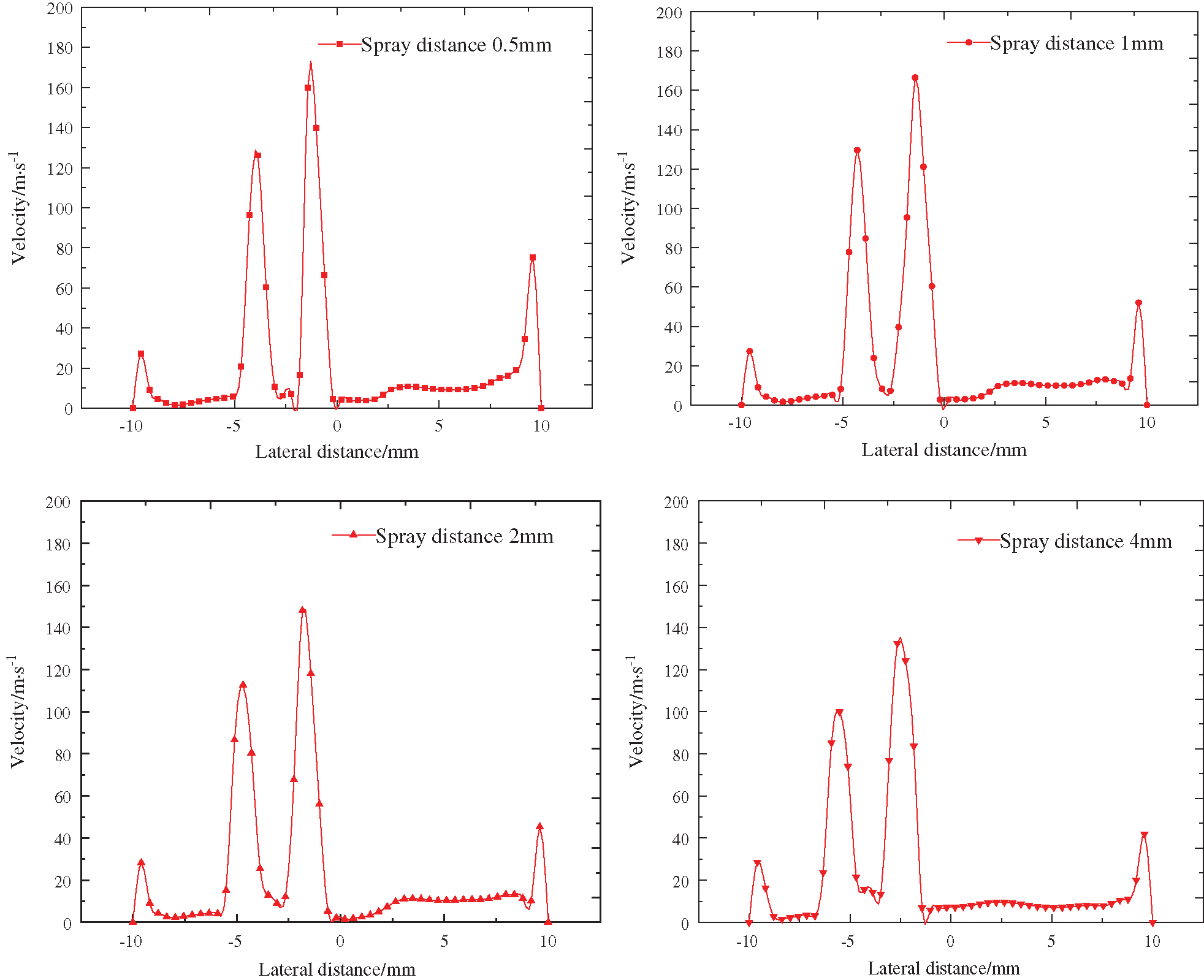
Figure 8: Velocity change curve under different spray distance
3.4 Influence of Rotating Speed on Jet Effect
Fig. 9 shows the velocity and dynamic pressure distribution of forward jet with different rotating speeds. It can be observed from the figure that two groups of different wave peaks are formed at the position of the forward jet at the position of 1 mm from the bottom hole jet, and there is no difference between the wave peaks at different rotating speeds. In the dynamic pressure distribution of forward jet at different rotating speeds, two groups of wave peaks are formed at the bottom of the well, and there is no significant difference in the peak values at different rotating speeds. The smaller the nozzle angle, the greater the velocity and dynamic pressure at the same bottom hole. In conclusion, the rotating speed can increase the tangential velocity of the jet in the process of rotation, but has no significant effect on the total velocity and dynamic pressure of the jet.
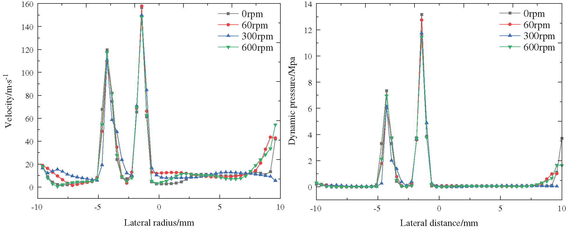
Figure 9: Velocity and dynamic pressure distribution of forward jet with different rotating speeds
4.1 Rock Samples Preparation and Experimental Equipment
The rock breaking experiment system using high-pressure water jet is shown in Fig. 10. The high-pressure plunger pump is used with a rated pressure of 100 Mpa and a rated flow of 120 L/min. In the rock breaking experiment, the jet inlet pressure is set to 40 Mpa, the starting drilling position is 10 mm, and there is no confining pressure submerged condition. The experiment uses sandstone with good homogeneity, and the specification is 100 × 100 mm (diameter × height), the uniaxial compressive strength is 36 Mpa, shear strength is 4.48 MPa, modulus of elasticity is 0.65 × 10⁴ MPa, and density is 2.711 × 10³ kg/m3.
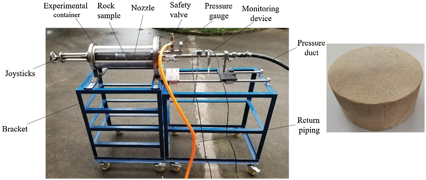
Figure 10: Rock breaking drilling experimental equipment and rock samples
4.2 Experimental Results and Discussion
Fig. 11 shows the rock-breaking and hole-forming effect of the multi-hole combined external rotation nozzle, revealing the dynamic process of the nozzle jet from contacting the impacting rock to each nozzle sequentially impacting and breaking the rock, forming a “progressive” rock breaking effect. It can be seen from the figure that as the nozzle advances, and under the action of the nozzle rotation, the 20° and 30° nozzle jets begin to impact the rock. When the jet velocity reaches the critical value of breaking rock, the 20° nozzle breaks the rock first. An inclined circular groove is formed on the rock, and then the 30° nozzle reaches the effective spray distance range, and the impact crushing surface is superimposed on the 20° nozzle oblique circular groove on the rock, and a circular groove spreading outward is formed on the rock. This is due to the large axial velocity of 20° and 30° nozzles, which mainly impacts and breaks the rock at the axial velocity, so deep grooves are formed in the rock; as the nozzle continues to advance, the 60° nozzle jet begins to contact the crushed rock; due to the large radial velocity, it is superimposed on the ring with a larger radial velocity, which causes the original crushing impact area to expand outward to form a larger aperture. At this point, the three holes are in complete contact with the rock. During this process, a convex cone is formed at the bottom of the borehole. Under the action of rotation, crushing can be achieved through grinding along with the circular scanning of the 20° nozzle. In addition, due to the spacing between the 20° and 30° nozzles, thread-line circular grooves appear on the wall of the borehole, and the 60° nozzle jet breaks the annular groove, making the wall surface of the borehole smooth and forming a regular borehole diameter. The angles of the nozzles of the multi-hole combined external rotation nozzle are different, so the jet axial velocity and radial velocity of each nozzle are different. Under the combined action of the three holes, a “progressive” drilling and rock-breaking process is formed.
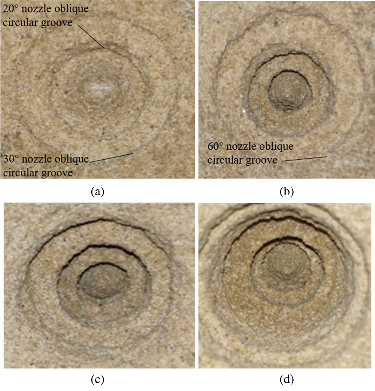
Figure 11: Schematic diagram of the experimental system (a) Two jets contact the rock (b) Three jets contact the rock (c) “Progressive” drilling (d) Complete hole formation
Compared with the dynamic rock-breaking hole-forming process, the superimposed scanning rock-breaking along their respective tracks is realized through the combination arrangement of different nozzles under the action of rotation, showing a “progressive” dynamic rock-breaking hole-forming process, and finally achieving the regular drilling effect. The simulation results of flow field characteristics are basically consistent with the actual dynamic rock-breaking process.
Acknowledgement: We are very grateful to the editor and anonymous reviewers for their valuable advices.
Funding Statement: This work is financially supported by the Science and Technology Innovation and Entrepreneurship Fund of China Coal Technology Engineering Group (2019-TD-QN038, 2019-TD-QN017), and Enterprise Independent Innovation Guidance Project (2018ZDXM05, 2019YBXM30).
Conflicts of Interest: We declare that there is no conflict of interests regarding the publication of this paper.
1. Li, G. S., Huang, Z. W., Li, J. B. (2017). Study of the key technique in radial jet drilling. Petroleum Drilling Techniques, 45(2), 1–9. [Google Scholar]
2. Bi, G., Li, G. S., Huang, Z. W., Gao, H., Dou, L. B. et al. (2018). Calculation and optimization of hydraulic parameters for hydraulic jet radial horizontal drilling. Journal of Xi’an Shiyou University (Natural Science Edition), 33(5), 76–82. [Google Scholar]
3. Li, Y. H., Wang, C. J., Shi, L. H., Guo, W. Y. (2000). Application and development of drilling and completion of the ultrashort-radius radial well by high pressure jet flow techniques. Society of Petroleum Engineers Inc, 39, 1–5. [Google Scholar]
4. Li, J. B., Li, G. S., Huang, Z. W., Song, X. Z., Li, K. (2015). Flow field study on a new kind swirling multi-orifices nozzle. Fluid Machinery, 43(7), 32–36. [Google Scholar]
5. Liao, H. L., Li, G. S., Niu, J. L., Huang, Z. W. (2013). Integrating straight & swirling jets bit design and its rock breaking characteristics for radial horizontal hole drilling. Journal of China Coal Society, 38(3), 424–429. [Google Scholar]
6. Song, X. Z., Lyu, Z. H., Cui, L., Li, G. S., Ji, G. D. et al. (2017). Comparison of numerical analysis on the downhole flow for multi-orifice hydrothermal jet drilling technology for geothermal wells. Geothermics, 70(4–6), 314–323. DOI 10.1016/j.geothermics.2017.07.004. [Google Scholar] [CrossRef]
7. Du, P. (2016). Study on the flow field and rock breakingstudy on the flow field and rock breaking mechanism of straight-swirling integrated jet (Ph.D. Thesis). Chongqing University, China. [Google Scholar]
8. Liao, H. L., Niu, J. L., Cheng, Y. X., Huang, Z. W., Ma, D. J. (2011). Experiment study on water jet breaking rock by multi-orifice nozzle. Journal of China Coal Society, 36(11), 1858–1862. [Google Scholar]
9. Ma, D. J., Li, G. S., Niu, J. L., Liao, H. L., Huang, Z. W. (2015). Experimental study on rock breaking and drilling laws by multi-hole jet bit. Fluid Machinery, 43(3), 1–5. [Google Scholar]
10. Xiao, S., Ren, Q., Ge, Z., Chen, B., Wang, F. (2020). Study of the rock-breaking and drilling performance of a self-rotatory water-jet bit in water-jet drilling and its influential factors. Energy Sources, Part A: Recovery, Utilization, and Environmental Effects. DOI 10.1080/15567036.2020.1767732. [Google Scholar] [CrossRef]
11. Bi, G., Li, G. S., Qu, Z., Niu, J. L., Huang, Z. W. et al. (2016). Rock breaking efficiency of the self-propelled swirling jet bit. Acta Petrolei Sinica, 37(5), 680–687. [Google Scholar]
12. Li, J. B., Li, G. S., Huang, Z. W., Song, X. Z., He, Z. G. et al. (2017). A discussion about the method to study the effect of ambient pressure on hydraulic jetting. Journal of Petroleum Science and Engineering, 149(1), 203–207. DOI 10.1016/j.petrol.2016.10.043. [Google Scholar] [CrossRef]
13. Li, L., Wang, F. X., Li, T. Y. (2018). Design and application of multiple swirling jet nozzle of radial horizontal well. Fault-Block Oil & Gas Field, 25(2), 244–248. [Google Scholar]
14. Liu, Y. B., Ba, Q. B., He, L. P., Shen, K., Xiong, W. (2020). Study on the rock-breaking effect of water jets generated by self-rotatory multinozzle drilling bit. Energies Sciences & Engineering, 8(7), 2457–2470. [Google Scholar]
15. Jia, X. (2016). Design and experimental study on self-propelled rotatory jet bit for radial horizontal drilling (Ph.D. Thesis). China University of Petroleum (East ChinaChina. [Google Scholar]
16. Ansys, Inc. (2009). ANSYS FLUENT 12.0 user’s guide—26.3.1 choosing the pressure-velocity coupling method. https://www.afs.enea.it/project/neptunius/docs/fluent/html/ug/node785.htm. [Google Scholar]
17. Sun, C., Shang, J., Luo, Z., Li, X., Lu, Z. et al. (2020). CFD simulation and experimental study of a new elastic blade wave energy converter. Fluid Dynamics & Materials Processing, 16(6), 1147–1159. DOI 10.32604/fdmp.2020.09937. [Google Scholar] [CrossRef]
18. Yan, Q., Li, Y., Zhu, Y., Cheng, K., Huang, X. et al. (2020). CFD-based optimization of hot primary-air pipe networks in power plant milling systems. Fluid Dynamics & Materials Processing, 16(3), 623–636. DOI 10.32604/fdmp.2020.09669. [Google Scholar] [CrossRef]
 | This work is licensed under a Creative Commons Attribution 4.0 International License, which permits unrestricted use, distribution, and reproduction in any medium, provided the original work is properly cited. |