| Fluid Dynamics & Materials Processing |
DOI: 10.32604/fdmp.2021.015638
ARTICLE
Visualization of Water Plugging Displacement with Foam/Gel Flooding in Internally Heterogeneous Reservoirs
1Dagang Oilfield Company, China National Petroleum Corporation, Binhai New Area, Tianjin, 300280, China
2The Unconventional Oil and Gas Institute, China University of Petroleum, Beijing, 102249, China
3Beijing Jinshi Liyuan Science Co., Ltd., Beijing, 102206, China
*Corresponding Author: Tongjing Liu. Email: ltjcup@cup.edu.cn
Received: 01 January 2021; Accepted: 07 April 2021
Abstract: During the displacement of water plugging with binary flooding in internally heterogeneous reservoirs, it is essential to understand the distributions of remaining oil as well as the oil displacement mechanisms at different stages. In this study, two types of internally heterogeneous systems, i.e., vertical and horizontal wells are investigated experimentally through a microscopic approach. The results show that plugging agent types have a greater impact on oil recovery than well types, and foam injection can enhance oil recovery more effectively than gel injection. Additionally, the injection sequence of plugging agents significantly affects oil displacement efficiency. Injecting gel after foam is more beneficial. According to the present results, the main formation mechanisms of remaining oil in each displacement stage are influenced by: capillary force, viscous force, inertial force, shear force, microscopic fingering & channeling.
Keywords: Microscopic visualization experiment; internally heterogeneous reservoir; remaining oil; foam; gel
The amount and location of the remaining oil in reservoirs are the key factors to be considered during the design and adjustment for the Enhanced Oil Recovery (EOR) operations. The remaining oil distribution in reservoir can be classified into two types including macroscopic and microscopic according to the size of the research scale [1,2]. Research methods of remaining oil can be classified as follows [3–9]: development geology, sequence stratigraphy, reservoir engineering, well logging, numerical simulation, physical simulation, and microscopic experiment. The internal relationship between the two classification methods is that the first six research methods belong to macroscopic analysis while the microscopic experiment method concentrates on microscopic analysis. Recently, with the combination of nuclear magnetic resonance (NMR) technology and core displacement experiment [10–19], the visualization technology from macroscopic displacement to micro imaging has been realized. However, this visualization technology has not yet reached the level of microscopic scale.
The microscopic scale research is the study on the scale of the pore structure from a few microns to a few millimeters, which can be considered as the smallest scale for studying oil displacement mechanisms and the remaining oil distribution at present. The microscopic visualization method and equipment are required to realize the microscopic scale research. The existing microscopic visualization method is to etch the micro two-dimensional pore structure on the optical glass plate by laser etching technology to imitate the porous structure of the reservoir. The microscopic image of the displacement process can be amplified by the microscope and then captured during the microscopic flooding processes. The captured image can be transferred to the computer simultaneously for the following analysis. Efforts have been done to investigate the remaining oil for the homogeneous reservoir by the microscopic visualization method. So far, few attempts have been made to analyze the remaining oil distribution during complex water shutoff operations for a heterogeneous reservoir by this visualization method.
Due to the difficulty of making heterogeneous optical glass plates and the complexity of displacement process for water plugging with binary systems in internally heterogeneous reservoirs, the numerical simulation method, core displacement method, and macroscopic visualization method are usually chosen to investigate the water shutoff operations with binary systems in internally heterogeneous reservoirs. Few attempts have been made with the microscopic scale visualization method. Besides, the types and distribution characteristics of the remaining oil, as well as the displacement mechanisms during each displacement stage of water shutoff operations with binary systems in internally heterogeneous reservoirs, are still unclear. Therefore, this study carried out a series of microscopic visualization experiments in the internally heterogeneous models with vertical and horizontal well patterns, to investigate the remaining oil types, distribution characteristics, and generation mechanisms based on the analysis of microscopic visualization images.
2 Microscopic Visualization Experiments
(1) Brine preparation. Formation water with a total salinity of 0.7 × 10⁴ mg/L, and the content of calcium and magnesium ions was 0.02 × 10⁴ mg/L in this study.
(2) Foam system preparation. Because the target reservoir is in the conditions of high temperature and high salinity, the properties of the foam system should be screened and optimized before the experiments. THS-1 was selected as a foaming agent with an optimal concentration of 0.25%. The interfacial tension between the surfactant and crude oil was 1.94 mN/m. The foam system was injected by mixing N2 with foaming agent of THS-1, and the injection rate was 1 ml/min with the gas-liquid ratio of 1:1.
(3) Polymer solution preparation. LF polymer was selected in this study since it has a strong temperature and salt resistance. The optimal concentration was 0.6 wt%, and the viscosity of LF polymer solution was 275 mPa·s at room conditions.
(4) Crude oil preparation. Crude oil with a viscosity of 1.73 mPa·s at reservoir conditions was used.
The micro two-dimensional pore structure was etched on optical glass plates with laser etching technology. The pore size of the model was between 0.01-0.1 mm. Therefore, the model could represent internally heterogeneous reservoirs with high-medium-low permeability zones precisely. This study applied a vertical well model (the point export as a vertical well, as shown in Fig. 1a) and a horizontal well model (the horizontal export as a horizontal well, as shown in Fig. 1b). The simulated permeability of three different permeability zones was 4000 mD, 2000 mD, and 200 mD, respectively.
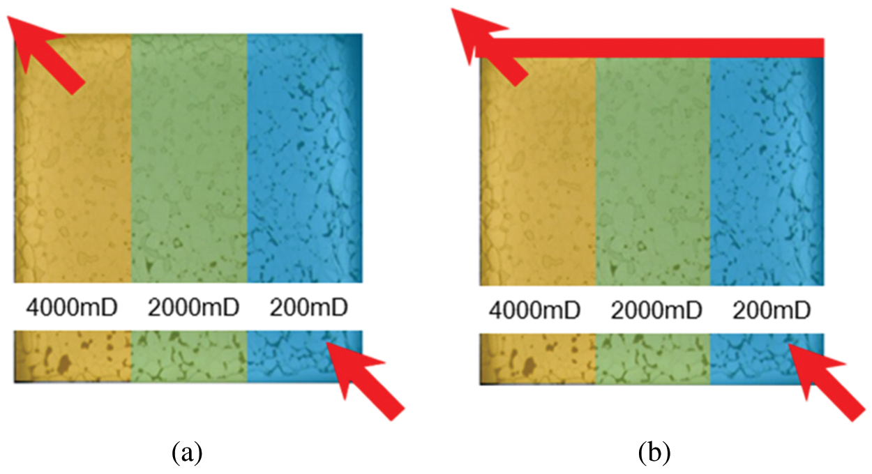
Figure 1: Experimental models (a) Vertical well model (b) Horizontal well model
The schematic and equipment of the microscopic visualization experiment are shown in Fig. 2.
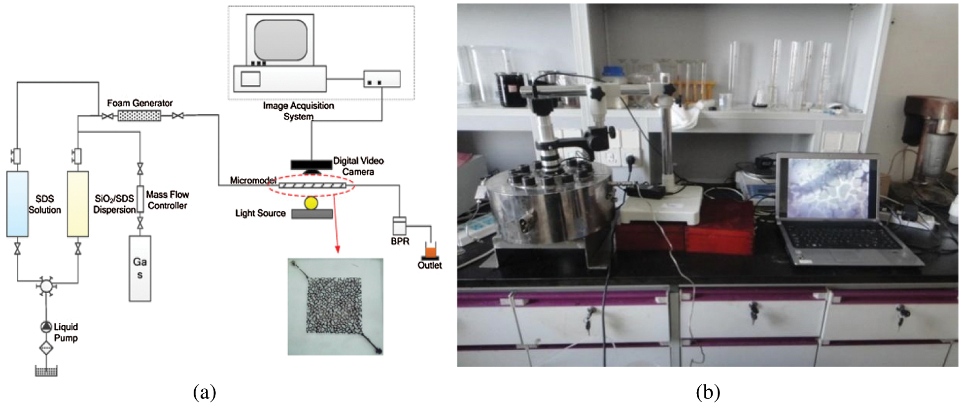
Figure 2: Microscopic visualization experiment setup (a) Schematic (b) Equipment
Experimental procedures were detailed as follows:
(1) Water was injected into the micro model within the core holder, and the confining pressure was added to 9 MPa.
(2) The temperature was heated to 80°C and maintained for 90 min.
(3) Backpressure was added to 8 MPa.
(4) Water was injected into the micro model at a specific flow rate. Turned on the micro camera and adjusted the focal length till the image was clear. After the flow was stable, the pressure detection system was applied to measure the pressure difference between the input point and the output point of the model.
(5) Foam system was injected into the micro model continuously with different rates and patterns to reach steady flow condition. Meanwhile, the generation of the foam in the micro porous media was videoed and captured. The pressure difference between the input and the output point of the model was measured when the foam system flowed steadily.
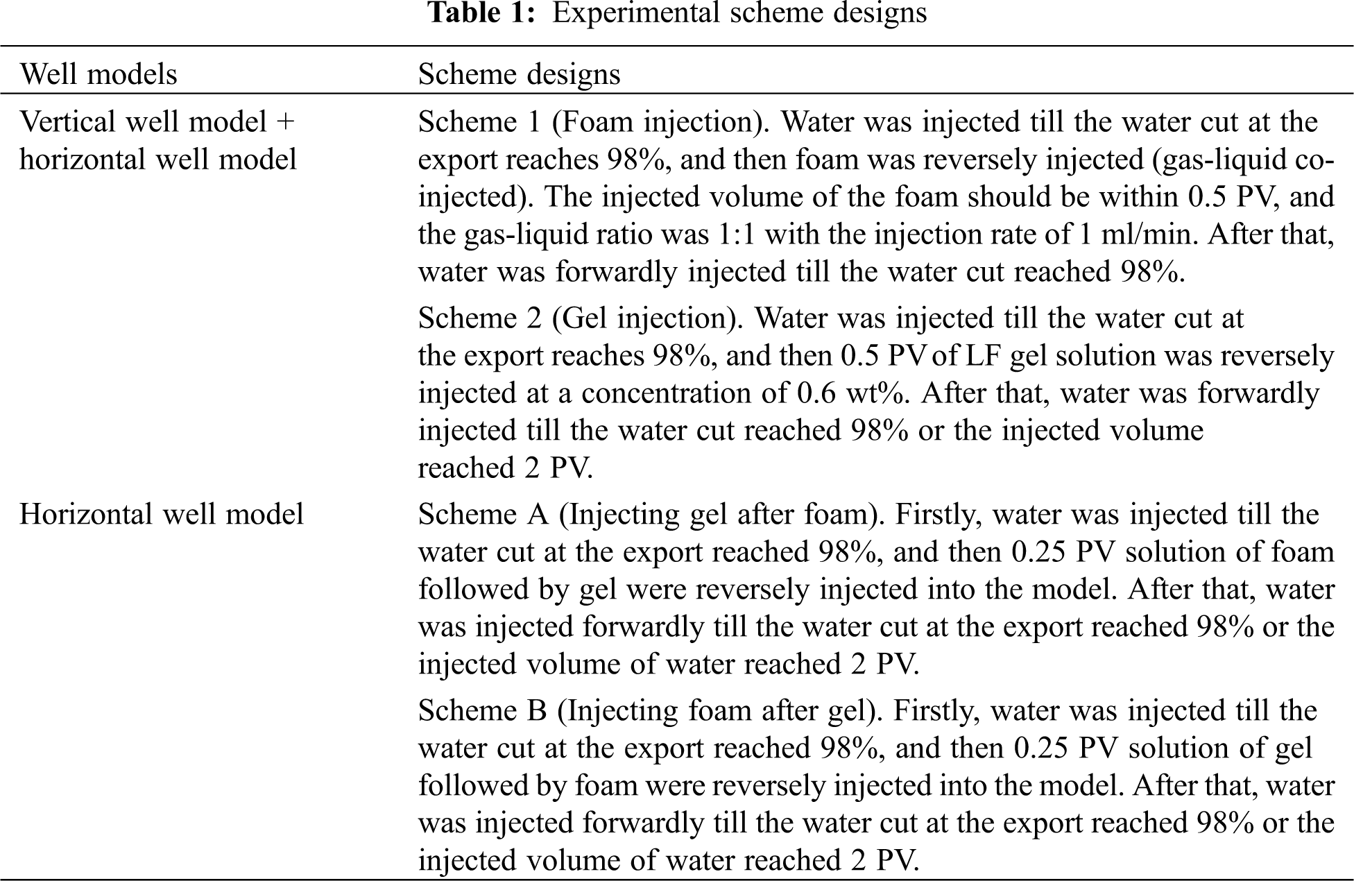
2.4 Experimental Scheme Designs
Two types of comparative experiments were implemented in this work: (1) the effect of injected plugging agents on oil recovery in both vertical and horizontal well models, (2) the influence of injection sequence of the plugging agents on oil recovery in the horizontal well models. The experimental scheme designs were detailed in Tab. 1.
3 Microscopic Visualization Experiment Results
3.1 Injection of Different Plugging Agents in the Vertical Well Model
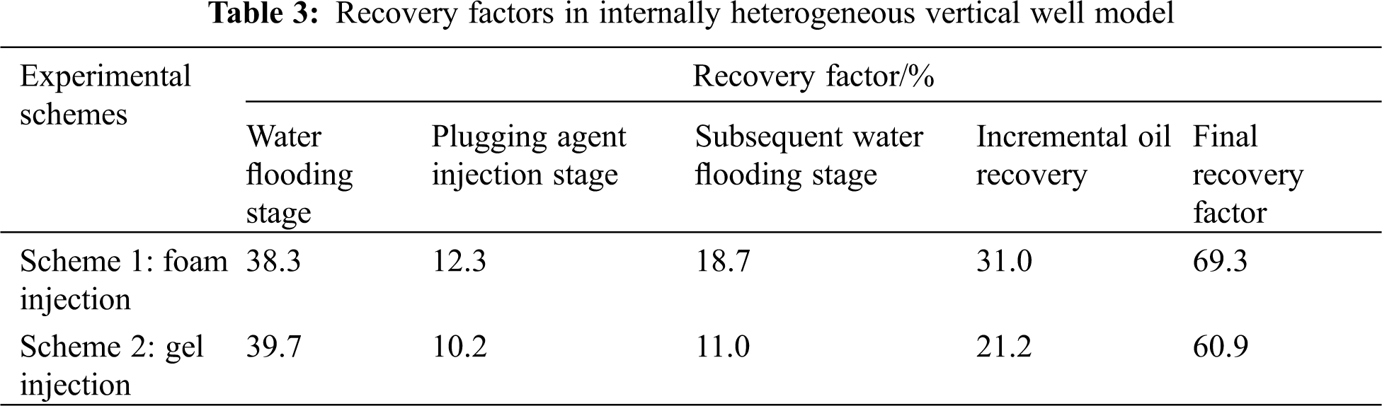
The distributions of remaining oil, the injected foam, and the injected gel in porous media at different displacement stages were observed and captured by conducting Schemes 1 and 2. Tab. 2 showed the remaining oil distributions at different displacement stages with different operation schemes. Recovery factors at different displacement stages in internally heterogeneous vertical well model with different operation schemes were summarized in Tab. 3.
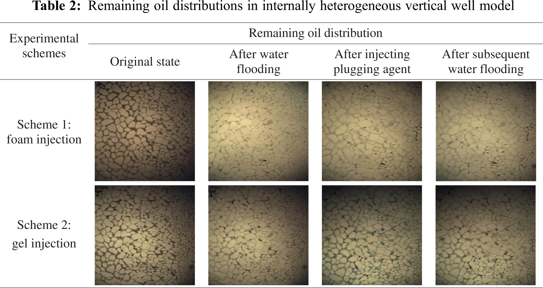
Experimental results showed that the oil recovery of Scheme 1 was similar to that of Scheme 2 at a water cut of 98% in the first water flooding stage. Then, after the plugging agent injection stage, the oil recovery factor of Scheme 1 was slightly higher than that of Scheme 2. After the subsequent water flooding stage, the oil recovery of Scheme 1 was 7.7% higher than that of Scheme 2. Overall, the final oil recovery of Scheme 1 was 8.4% higher than that of Scheme 2 which means the foam injection could be more effective to enhance oil recovery than gel injection.
As shown in Fig. 3, the distribution characteristics of remaining oil in the zones with different permeability were significantly different after the first water flooding stage. The remaining oil mainly existed in the un-swept area in medium and low permeability zones. The oil displacement efficiency in the high permeability zone was the highest among others, and the remaining oil can be trapped on the edge of large pores in the high permeability zone. The oil displacement efficiency in medium-low permeability zones was worse than that in the high permeability zone due to the poor sweep efficiency.
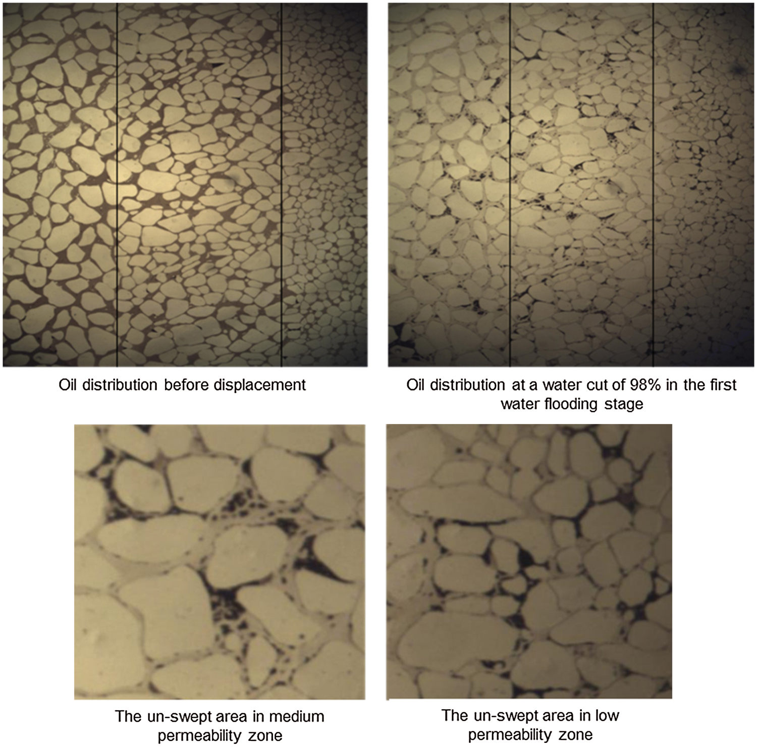
Figure 3: Distribution of remaining oil after water flooding stage in the vertical well model
As illustrated in Fig. 4, the oil displacement efficiency in the zones with different permeability were drastically different after injecting foam system, and the remaining oil mainly existed in un-swept areas in the low permeability zone. In medium and high permeability zones, oil was displaced effectively owning to the Jamin effect and the compressed effect caused by the foam. In addition, after the injection of the gel solution, the oil displacement efficiencies in different permeability zones were similar. The remaining oil in the large pores of the high/medium permeability zones was displaced. Meanwhile, gel occupied those large pores. The remaining oil in the high/medium permeability zones, mainly distributed in the edge of large pores, while the remaining oil in the low permeability zone, mainly distributed in un-swept areas.
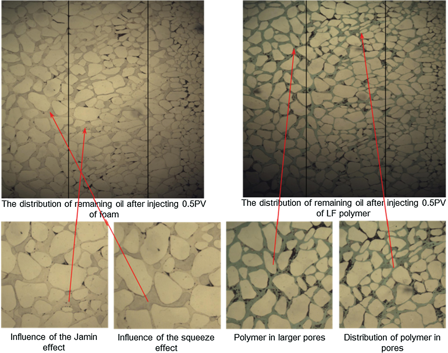
Figure 4: Distribution of remaining oil after plugging agent injection stage in the vertical well model
As shown in Fig. 5, after the subsequent water flooding, the oil displacement efficiency of Scheme 1 (foam injection) was significantly higher than that of Scheme 2 (gel injection). The remaining oil of Scheme 1 appeared in un-swept areas (i.e., the edge of the model). Remaining oil saturation of Scheme 2 (gel injection) remained high in the medium-low permeability zones.
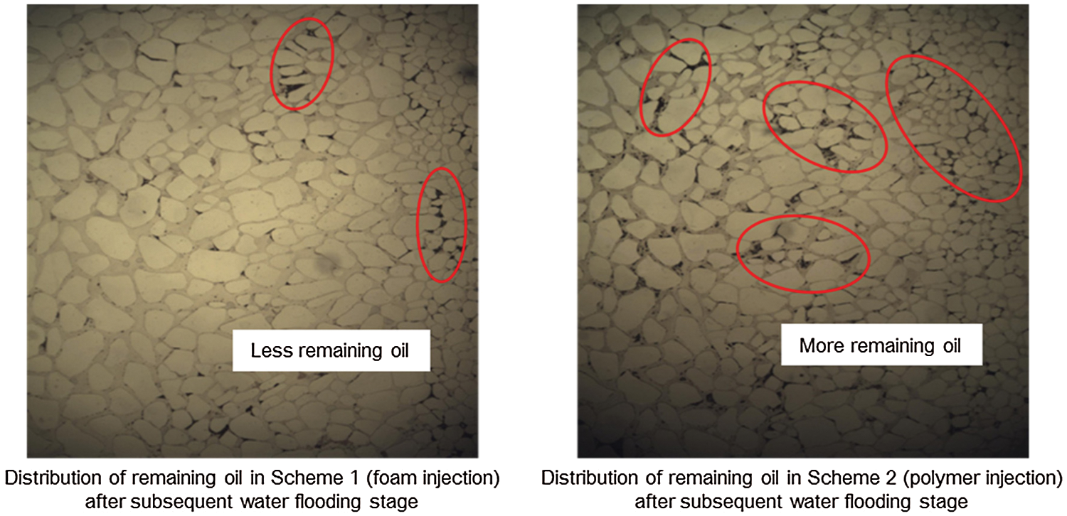
Figure 5: Distribution of remaining oil after subsequent water flooding in vertical well model
3.2 Injection of Different Plugging Agents in the Horizontal Well Model
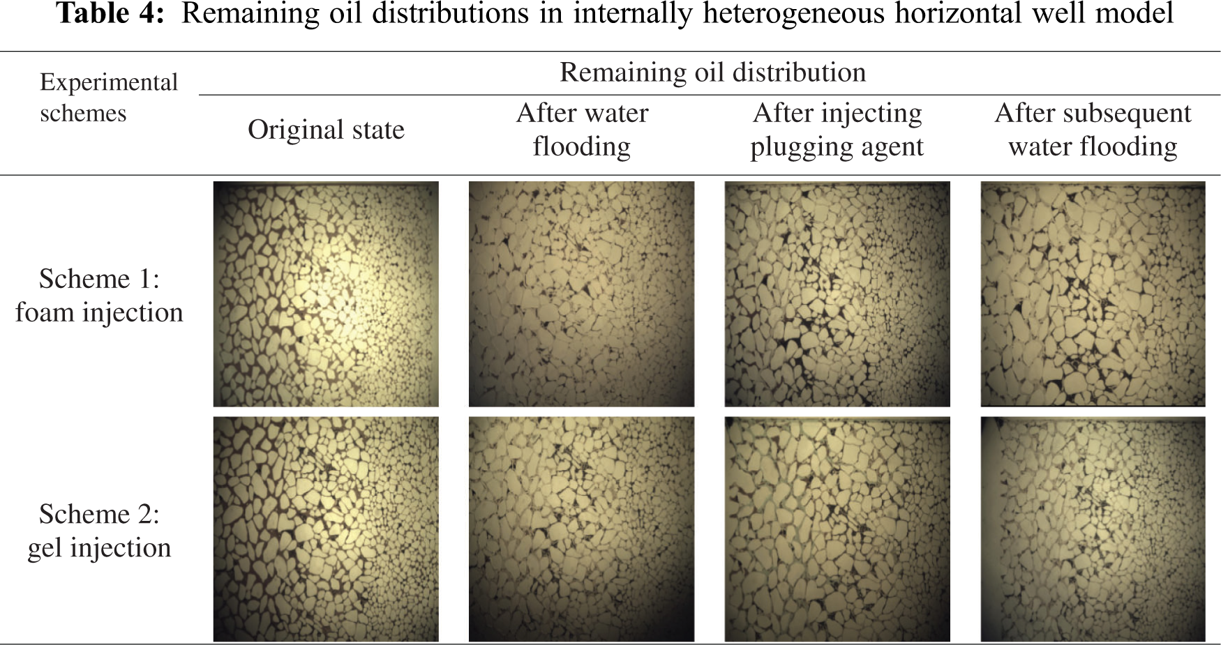
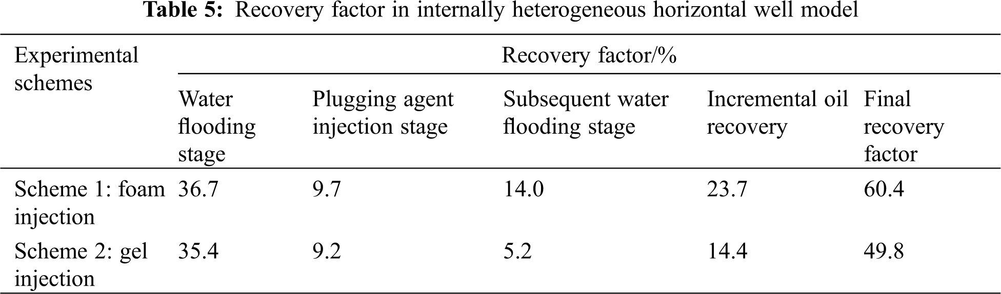
The distributions of remaining oil, foam and gel in porous media at different stages were observed captured by implementing Schemes 1 and 2. Tab. 4 showed the remaining oil distributions at different displacement stages with different operation schemes. Recovery factors at different displacement stages in internally heterogeneous horizontal well model with different operation schemes were summarized in Tab. 5.
Experimental results showed that the oil recovery of Scheme 1 was similar to that of Scheme 2 after water flooding stage. Then, after the plugging agent injection stage, the oil recovery factor of Scheme 1 (foam injection) was slightly higher than that of Scheme 2 (gel injection). After the subsequent water flooding stage, the oil recovery of Schemes 1 was 3 times higher than that of Scheme 2. Overall, the final oil recovery of Scheme 1 was 10.6% higher than that of Scheme 2 which means that the foam injection could be more effective to enhance oil recovery than gel injection.
As shown in Fig. 6, the distributions of remaining oil in different permeability zones were markedly different, and the remaining oil mainly distributed in medium and low permeability zones. The oil displacement efficiency in the high permeability zone was the highest among others. The remaining oil saturation in medium-low permeability zones remained high due to poor sweep efficiency.
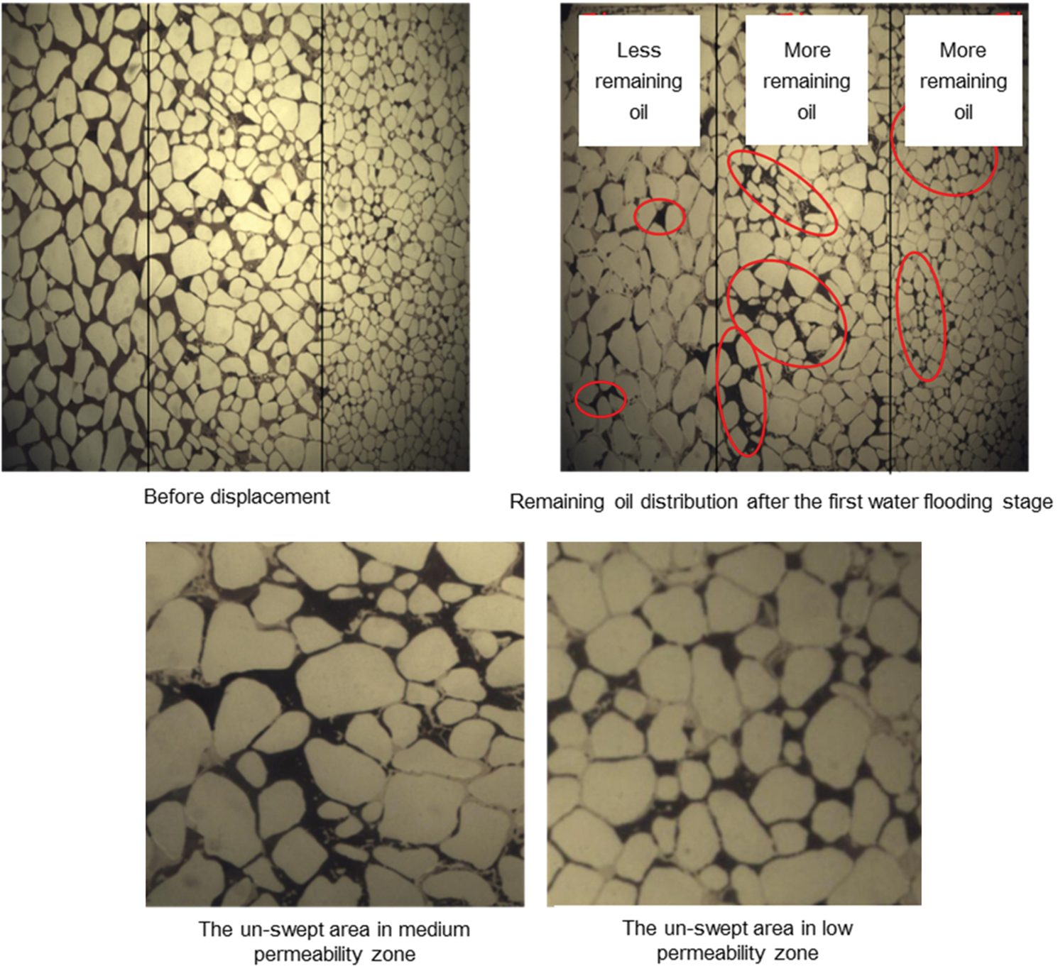
Figure 6: Distribution of remaining oil after the first water flooding stage
As shown in Fig. 7, after the foam injection, the oil displacement efficiency in three zones were not changed greatly compared with the first water flooding stage. The remaining oil saturation reduced near the export but remained high far from the export. The oil displacement efficiency of Scheme 2 (gel injection) was higher than that of Scheme 1 (foam injection). In high permeability zone, remaining oil in large pores was displaced, and these large pores were occupied by the injected gel. Remaining oil in the high permeability zone, mainly distributed on the edge of large pores; the remaining oil saturation in medium-low permeability zones remained high after the gel injection.
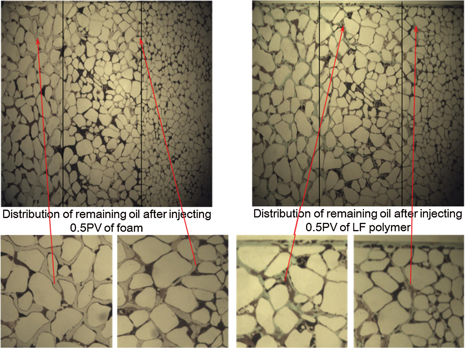
Figure 7: Distribution of remaining oil after plugging agent injection in the horizontal well model
Fig. 8 showed the remaining oil distribution after the subsequent water flooding. The oil displacement efficiency of Scheme 1 (foam injection) was higher than that of Scheme 2 (gel injection) in medium and low permeability zones. In addition, in medium and low permeability zones, remaining oil of Scheme 1 (foam injection) mainly distributed at the edge of large pores and in the dead pore volume; remaining oil saturation of Scheme 2 (gel injection) remained high.
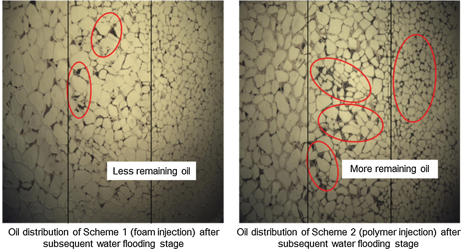
Figure 8: Distribution of remaining oil after subsequent water flooding in horizontal well model
3.3 Different Injection Sequence of Plugging Agents in the Horizontal Well Model
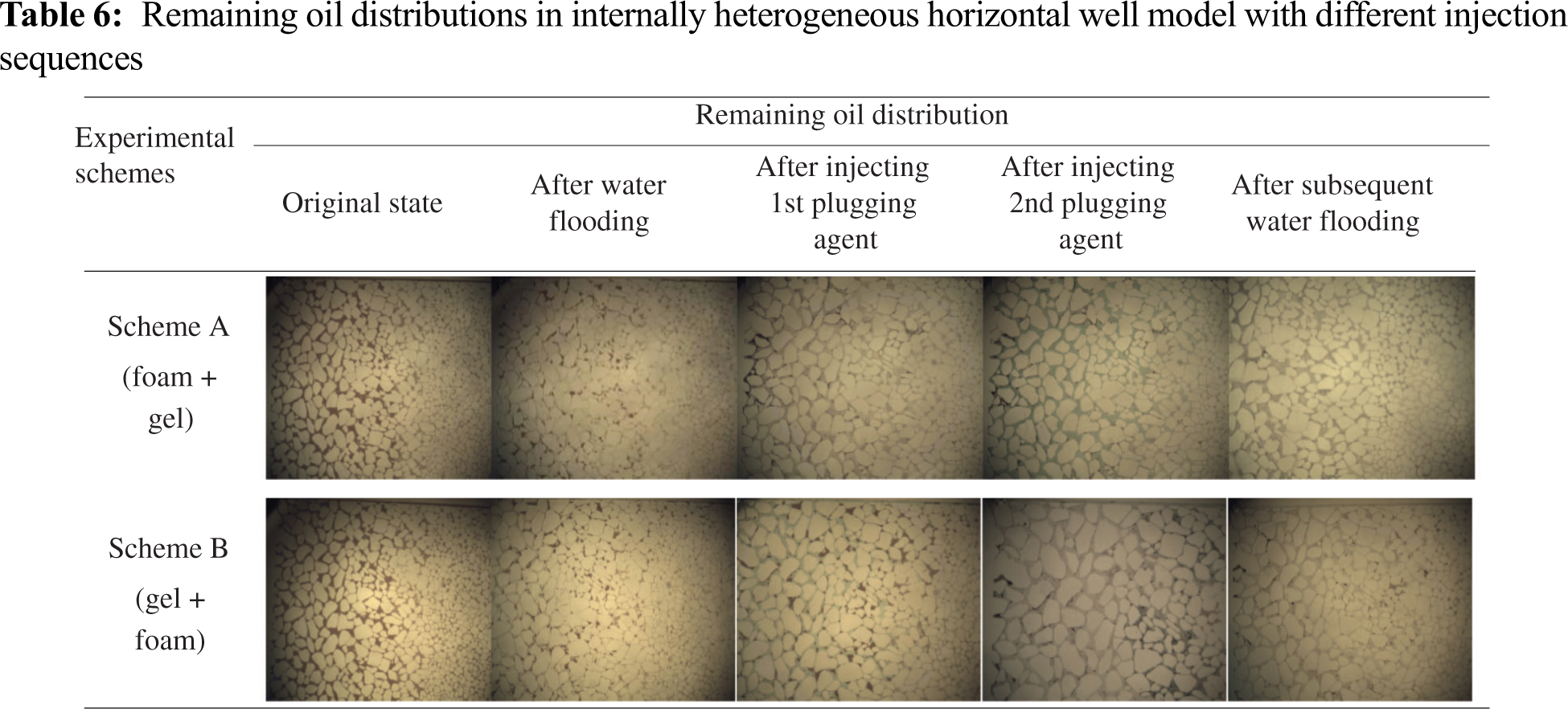
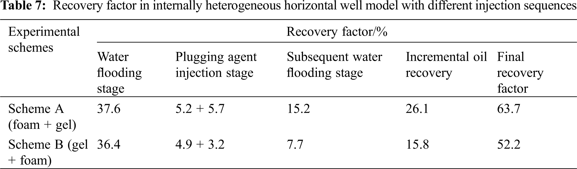
The distributions of remaining oil, foam and gel in the horizontal well model at different displacement stages were observed and captured by implementing Schemes A and Schemes B. Tab. 6 showed the remaining oil distributions at different displacement stages in internally heterogeneous horizontal well model with different injection sequences. Recovery factors at different displacement stages were obtained and summarized in Tab. 7.
From the experimental results shown in Tab. 7, the oil recovery of Scheme A is similar to that of Scheme B at a water cut of 98% in the first water flooding stage. Then, after the plugging agent injection stage, the oil recovery factor of Scheme A is slightly higher than that of Scheme B. After the subsequent water flooding stage, the oil recovery of Scheme A is twice that of Scheme B. Overall, the final oil recovery of Scheme A is 11.5% higher than that of Scheme B. Therefore, the injection sequence of plugging agents can affect incremental oil recovery significantly, and the oil displacement efficiency of Scheme A is markedly higher than that of Scheme B.
As shown in Fig. 9, remaining oil in medium and low permeability zones was displaced more effectively by implementing Scheme A, where the remaining oil only existed in un-swept areas. The remaining oil saturation of Scheme B in medium-low permeability zones remained high after the subsequent water flooding.
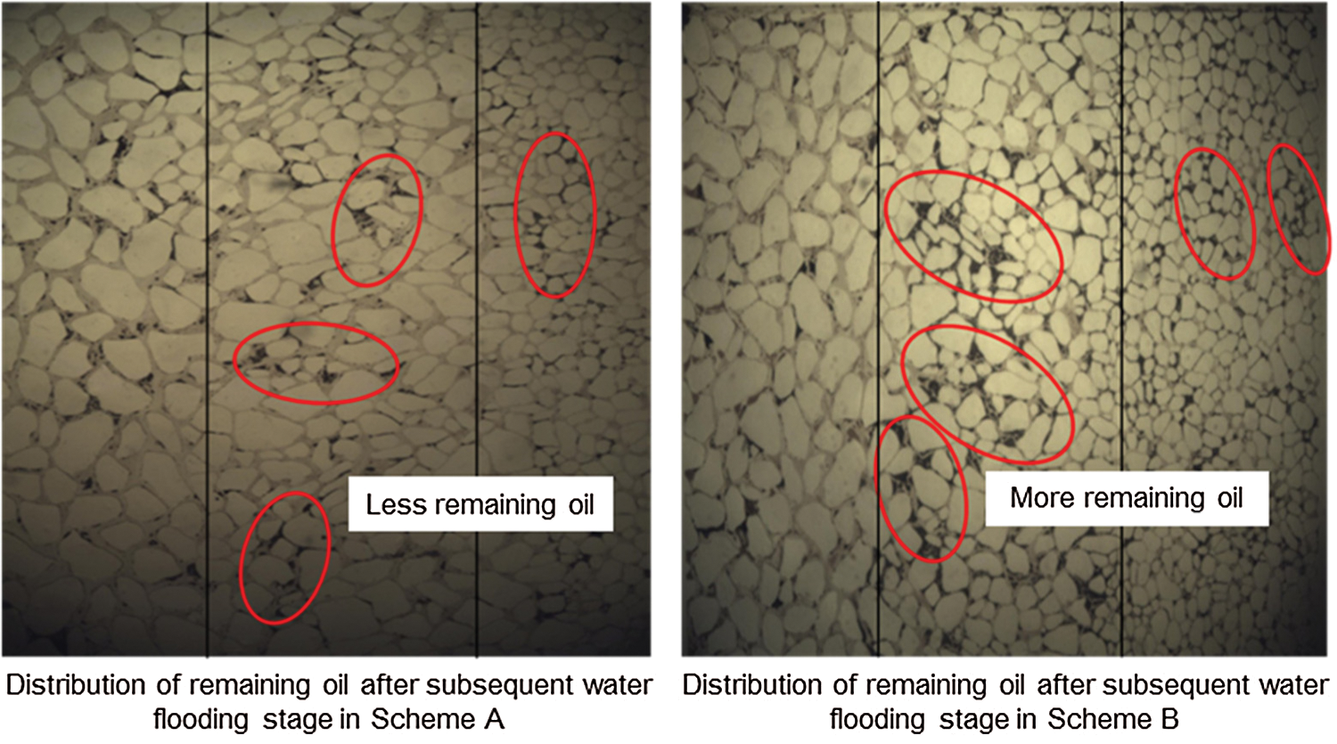
Figure 9: Distribution of remaining oil of Schemes A and B
4 Characteristics and Mechanisms of Microscopic Remaining Oil
As shown in Fig. 10, remaining oil can be classified into two types based on the pore space volume occupied by them, block-type and dispersed type. The former one, including the block-type remaining oil in the un-swept area and the cluster-like remaining oil in the swept area, occupied more pore spaces and mainly appeared in the primary recovery stage. The latter, including pole remaining oil, corner remaining oil and isolated remaining oil, occupied fewer pore spaces and mainly appeared in the secondary and tertiary recovery stages.
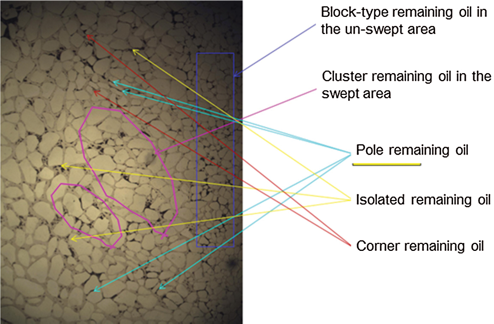
Figure 10: Types of remaining oil
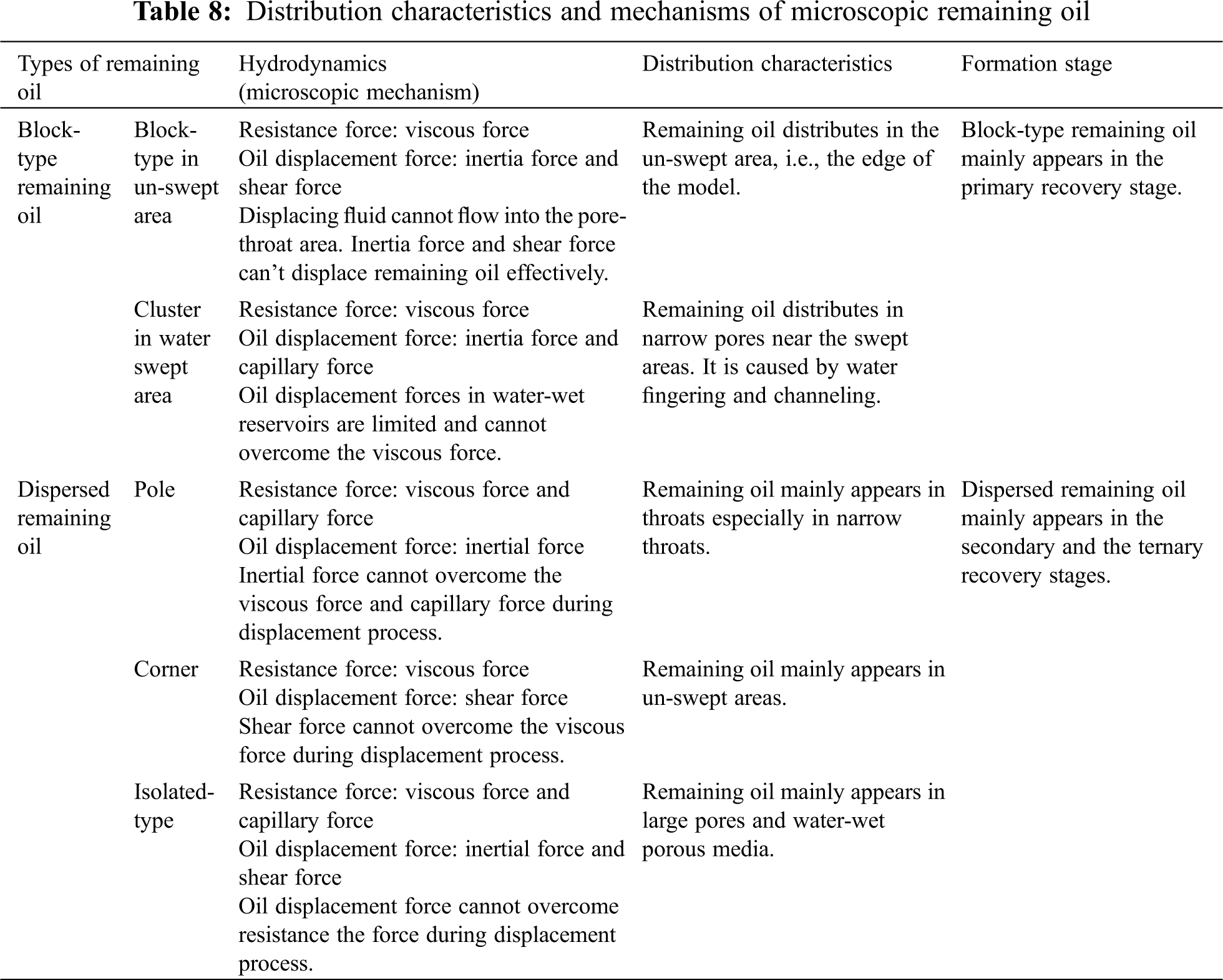
Flow in porous media can be affected by capillary force, viscous force, inertial force, shear force and so on [20–23]. In addition, experiment results showed that the following parameters affected the types and distribution characteristics of remaining oil during the water plugging operation: (1) capillary force, viscous force, inertial force, and shear force; (2) microscopic viscous fingering; (3) adhesion of the porous media (oil-wet); (4) microscopic water channeling due to heterogeneity; (5) the snap-off of oil flow caused by the high pore-throat aspect ratio. Tab. 8 detailed the effect of the factors on remaining oil distribution characteristics.
5 Analysis and Discussion of Oil Displacement Efficiency of Different Schemes
Based on the experimental results, in terms of the incremental oil recovery, the vertical well model outperformed the horizontal well model. The oil recovery difference between the two models was caused by the permeability distribution characteristics of the heterogeneous models and the well locations. For the vertical well model, the vertical well was located in the high permeability zone. For the horizontal well model, the horizontal well was located through the high-medium-low permeability zones. Therefore, the displacement efficiency of the vertical well was higher than that of the horizontal well, which caused a higher recovery for the vertical well model than for the horizontal well model. In addition, as shown in Fig. 11, Scheme 1 (foam injection) outperformed Scheme 2 (gel injection), and plugging agent types had a greater impact on the incremental oil recovery compared with well types.
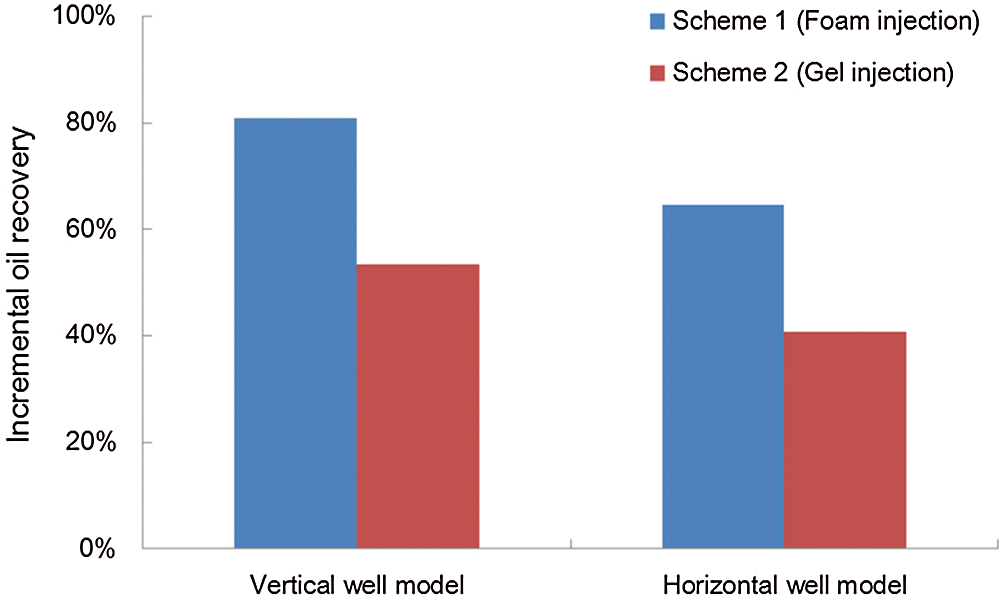
Figure 11: Comparison of incremental oil recovery between Schemes 1 and 2
Furthermore, for the horizontal well model, the oil recovery of Scheme A (foam + gel) was higher than that of Scheme B (gel + foam). As illustrated in Fig. 12, oil recovery during the foam injection period was lower than that during the gel injection period, which indicated that injecting foam before injecting gel strengthened the gel’s performance in oil displacement, whereas injecting gel before foam weakened the foam’s performance in displacing oil.
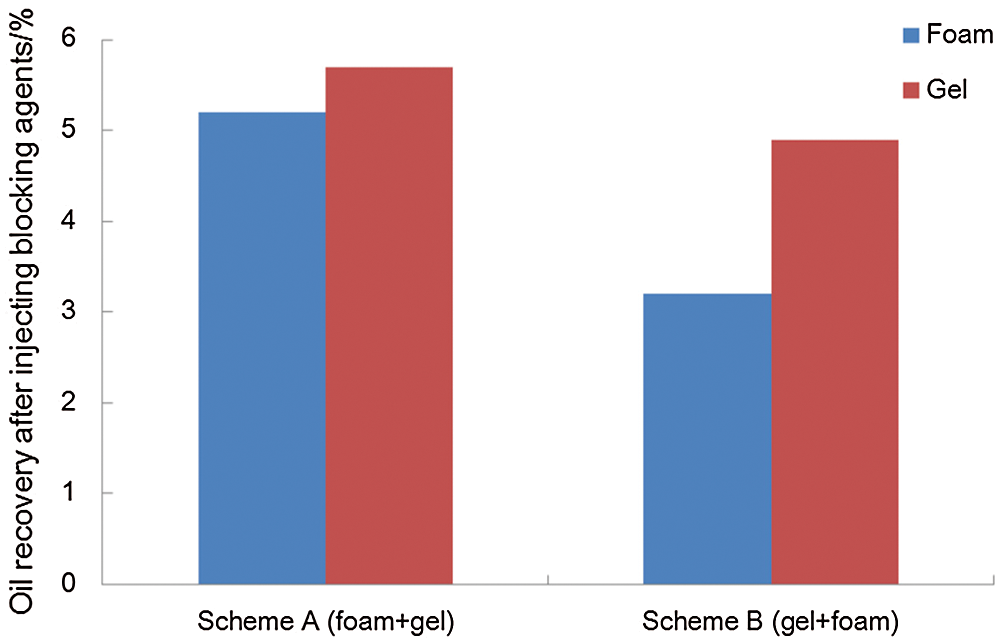
Figure 12: Comparison of oil recovery between Schemes A and B
In Scheme A, the injected foam selectively blocked high permeability and high water saturation zones, and the subsequently injected gel strengthened the foam’s blocking effectiveness. In Scheme B, the injected gel blocked some large pores, which could weaken the blocking effect of the foam.
Given the microscopic oil displacement mechanisms, foam injection has the following advantages compared with gel injection:
(1) The injected surfactant can alter the wettability of porous media, which is conducive to desorption of the crude oil from rock surfaces.
(2) Foam can change the rheology of crude oil, the viscosity and the limiting shear stress can be reduced.
(3) Interfacial tension can be reduced by the injected foam, oil droplets flow more easily through the throat and the oil flow rate can be increased as well.
(4) O/W (oil in water) emulsion can be formed after the addition of surfactant because of the emulsification and entrainment effect, so oil droplets in O/W emulsion can flow towards the area with lower pressure.
(5) Foam system has higher sweep efficiency compared with gel solution due to inherent properties of the foam (compressible non-Newtonian fluid).
(6) Due to Jamin effect, the injected foam can form resistance zones in both high permeability and high water saturation regions, thus it can block high permeability zone and activate low permeability zone.
(1) Based on the experimental results of different plugging agent types, it can be found that: 1) foam injection outperforms gel injection in terms of oil recovery and oil displacement efficiency; 2) plugging agent types have a greater impact on oil recovery compared with well types.
(2) Based on the experimental results of different injection sequence, we can find that: 1) the injection sequence of plugging agents significantly affects the oil displacement efficiency; 2) injecting foam system followed by gel solution can strengthen the oil displacement efficiency of the gel solution, while injecting gel first cannot strengthen the subsequent foam’s performance in improving oil displacement efficiency.
(3) During the displacement process of water plugging with binary systems, the remaining oil can be classified into two types: the block-type remaining oil (incl. block-type remaining oil in un-swept area and cluster remaining oil in swept area) and dispersed remaining oil (incl. pole remaining oil, corner remaining oil, and isolated remaining oil). The former one mainly appears at the primary displacement stage, while the latter mainly appears at the secondary and tertiary displacement stages.
(4) During the displacement process of water plugging with binary systems, the main formation mechanism of remaining oil can be summarized as follows: 1) capillary force, viscous force, inertial force and shear force; 2) microscopic fingering due to viscosity difference; 3) adhesion in porous media; 4) water channeling due to heterogeneity; 5) oil truncation due to pore-roar resistance mutation.
Acknowledgement: The authors will like to thank Dagang Oilfield Company and China University of Petroleum (Beijing) for all the technical discussions and scientific inputs during the study. The authors would also like to thank China University of Petroleum (Beijing) and China University of Geosciences (Beijing) for their assistance in setting up the experiments.
Funding Statement: The authors received no specific funding for this study.
Conflicts of Interest: The authors declare that they have no conflicts of interest to report regarding the present study.
1. Yan, W. C., Sun, J. M. (2016). Analysis of research present situation of microscopic remaining oil. Progress in Geophysics, 31(5), 2198–2211. [Google Scholar]
2. Markus, B., Castanier, L. M., Kovscek, A. R. (2012). Microvisual investigation of foam flow in ideal fractures: Role of fracture aperture and surface roughness. SPE Annual Technical Conference and Exhibition, 159430. [Google Scholar]
3. Wu, Z. B., Liu, H. Q., Pang, Z. X., Wu, C., Gao, M. (2016). Visualization experiment of nitrogen foam assisted steam-flooding in heavy-oil reservoir. Special Oil and Gas Reservoirs, 23(5), 126–129. [Google Scholar]
4. Wang, J. J., Li, Y. J., Gong, H. J., Li, R. H., Dong, M. Z. (2015). Micro-model experiment comparison of polymer, polymer surfactant and alkali surfactant polymer flooding. Oilfield Chemistry, 32(3), 401–405. [Google Scholar]
5. Di, Q. F., Hu, S., Gu, Y. C., Ye, F., Pang, D. S. et al. (2016). Study of micro flow visualization with nuclear magnetic resonance in core. Journal of Experiments in Fluid Mechanics, 30(3), 98–103. [Google Scholar]
6. Hu, S. (2016). Visualization experimental and numerical simulation study on the seepage and oil-displacement characteristics of weak gel in porous media (Ph.D. Thesis). Shanghai University, China. [Google Scholar]
7. Di, Q. F., Zhang, J. N., Hu, S., Chen, H. J., Gu, Y. C. (2017). Visualization experiments on polymer-weak gel profile control and displacement by NMR technique. Petroleum Exploration and Development, 44(2), 270–274. [Google Scholar]
8. Zhang, J. N., Di, Q. F., Hu, S., Ye, F., Li, Y. et al. (2018). Nuclear magnetic resonance experiments on foam flooding and evaluation of foam dynamic stability. Petroleum Exploration and Development, 45(5), 853–860. [Google Scholar]
9. He, J. H., Zhang, S. L. (2006). Microscopic remaining oil distribution in high water cut period. Journal of Oil and Gas Technology, 28(4), 340–344. [Google Scholar]
10. Das, A., Mohanty, K., Nguyen, Q. (2021). A pore-scale study of foam-microemulsion interaction during low tension gas flooding using microfluidics-Tertiary recovery. Journal of Petroleum Science and Engineering, 203, 108596. [Google Scholar]
11. Das, A., Mohanty, K., Nguyen, Q. (2021). A pore-scale study of foam-microemulsion interaction during low tension gas flooding using microfluidics-secondary recovery. Journal of Petroleum Science and Engineering, 201, 108444. [Google Scholar]
12. Gaol, C. L., Ganzer, L., Mukherjee, S., Alkan, H. (2021). Parameters govern microbial enhanced oil recovery (meor) performance in real-structure micromodels. Journal of Petroleum Science and Engineering, 205, 108814. [Google Scholar]
13. Azarhava, H., Jafari, A., Vakilchap, F., Mousavi, S. M. (2021). Stability and performance of poly γ-(glutamic acid) in the presence of sulfate ion for enhanced heavy oil recovery. Journal of Petroleum Science and Engineering, 196, 107688. [Google Scholar]
14. Rezaeiakmal, F., Parsaei, R. (2021). Visualization study of polymer enhanced foam (PEF) flooding for fecovery of waterflood residual oil: Effect of cross flow. Journal of Petroleum Science and Engineering, 203, 108583. [Google Scholar]
15. Das, A., Nguyen, N., Farajzadeh, R., Southwick, J. G., Vincent, S. et al. (2018). Laboratory study of injection strategy for low-tension-gas flooding in high salinity, Tight Carbonate Reservoirs. SPE, 190348. [Google Scholar]
16. Das, A., Nguyen, N., Farajzadeh, R., Southwick, J. G., Vincent, S. et al. (2019). Experimental Study of injection strategy for low-tension-gas flooding in low permeability, high salinity carbonate reservoirs. Journal of Petroleum Science and Engineering, 184, 106564. [Google Scholar]
17. Das, A., Nguyen, N., Nguyen, Q. P. (2019). Low tension gas flooding for secondary oil recovery in low-permeability, High-Salinity Reservoirs. Fuel, 116601. [Google Scholar]
18. Hauhs, F., Fodisch, H., Hincapie, R. E., Ganzer, L. (2018). Novel evaluation of foam and immiscible gas flooding in glass-silicon-glass micromodels. SPE, 190815. [Google Scholar]
19. Panahpoori, D., Rezvani, H., Parsaei, R., Riazi, M., Ms, D. P. (2019). A pore-scale study on improving CTAB foam stability in heavy crude oil water system using TiO2 nanoparticles. Journal of Petroleum Science and Engineering, 183, 106411. [Google Scholar]
20. Chen, J., Zhan, X. H. (2018). Experimental study on the startup sequence and oil displacement efficiency of micro remaining oil by chemical flooding. Offshore Oil, 38(2), 46–53. [Google Scholar]
21. Hou, J. R., Zhang, F. M., Zhao, F. L., Song, W. X., Lu, Y. et al. (2015). The microscopic study on mechanisms and the optimization of oil displacement by different chemical ecosystems. Science Technology and Engineering, 15(10), 72–82. [Google Scholar]
22. Liu, Y. S., Su, Y. B., Wu, Z. H., Luo, W., Liao, R. Q. (2020). Effect of the inclination angle on slippage loss in gas-liquid two-phase flow. Fluid Dynamics & Materials Processing, 16(3), 475–488. [Google Scholar]
23. Neffah, Z., Kahalerras, H., Fersadou, B. (2018). Heat and mass transfer of a non-newtonian fluid flow in an anisotropic porous channel with chemical surface reaction. Fluid Dynamics & Materials Processing, 14(1), 39–56. [Google Scholar]
 | This work is licensed under a Creative Commons Attribution 4.0 International License, which permits unrestricted use, distribution, and reproduction in any medium, provided the original work is properly cited. |