| Fluid Dynamics & Materials Processing |
DOI: 10.32604/fdmp.2021.015710
ARTICLE
Hydrodynamic Lubrication of Elastic Foil Gas Bearing Using Over Relaxation Iteration Method and Non-Dimensional Equation
School of Mechanical Engineering, Xi’an Jiaotong University, Xi’an, 710049, China
*Corresponding Author: Xiangxi Du. Email: rocket4@gmail.com
Received: 07 January 2021; Accepted: 22 April 2021
Abstract: The purpose is to accurately predict the performance of foil bearing and achieve accurate results in the design of foil bearing structure. A new type of foil bearing with surface microstructure is used as experimental material. First, the lubrication mechanism of elastic foil gas bearing is analyzed. Then, the numerical solution process of the static bearing capacity and friction torque is analyzed, including the discretization of the governing equation of rarefied gas pressure based on the non-dimensional modified Reynolds equation and the over relaxation iteration method, the grid planning within the calculation range, the static solution of boundary parameters and static solution of the numerical process. Finally, the solution program is analyzed. The experimental data in National Aeronautics and Space Administration (NASA) public literature are compared with the simulation results of this exploration, so as to judge the accuracy of the calculation process. The results show that under the same static load, the difference between the minimum film thickness calculated and the test results is not obvious; when the rotor speed of the bearing is 60000 r/min, the influence of the boundary slip effect increases with the increase of the micro groove depth on the flat foil surface; when the eccentricity or the micro groove depth of the bearing increases, the bearing capacity will be strengthened. When the eccentricity is 6 µm and 14 µm, the viscous friction torque of the new foil bearing increases significantly with the increase of the depth of the foil micro groove, but when the eccentricity is 22 µm, the viscous friction torque does not change with the change of the depth of the foil micro groove. It shows that the bearing capacity and performance of foil bearing are improved.
Keywords: Over relaxation iteration method; non-dimensional equation; elastic foil gas bearing; hydrodynamics; lubrication characteristics
For rotating machinery, the core component is its bearing. Bearing performance directly affects the normal operation of rotating machinery [1]. At the same time, the dynamic performance of bearings also has an important impact on the dynamic characteristics of high-speed rotor system of rotating machinery [2]. In recent years, with the rapid development of low-temperature engineering, precision machining and aerospace technology, the power and energy density of rotating machinery have been greatly enhanced. Therefore, the stability of the rotor system needs to be improved and it needs to work at a higher speed, which puts forward higher standards for bearing performance [3].
The principle of dynamic pressure gas foil bearing is based on elastic structure self-acting dynamic pressure flexible bearing [4], which has a very broad application prospect in oil-free rotating machinery. When gas foil bearing is used to replace oil lubricated bearing, the rotating machinery can run stably and reliably at higher speed, and the friction loss is very low. The elastic characteristics of foil lead to the high impact resistance of foil bearing and the high tolerance to rotor thermal expansion and centrifugal expansion [5]. At the same time, the friction effect between the flat foil and the support foil, and between the support foil and the bearing pedestal can eliminate a lot of useless energy, thus improving the damping characteristics of the foil bearing and improving the stability of the rotor system [6]. Since the 1970s, the research on gas foil bearing has gradually increased and deepened, and foil bearing has been gradually successfully applied to high-speed light load rotating machinery such as air circulator and oil-free turbo expander [7]. At present, some studies in related fields are still based on the dynamic model of micro rotor gas bearing spindle system based on Reynolds equation. The static and dynamic characteristic equations of single pad of tilting pad radial hydrodynamic gas bearing are solved by finite difference under relaxation method. Moreover, some studies on gas bearing are mainly about the forced nonlinear response of the bearing and the static and dynamic characteristics of aerostatic bearing with orifice throttling are analyzed by finite difference method. However, there are still many deficiencies in the research of foil bearing. First, foil bearings can be generally used in high-speed light load rotating machinery. Its structure size is very small, the lubricating film is very thin, and the lubricating gas has a certain thinning effect [8]. Then, at low speed, the contact friction state between the flat foil and the rotor surface slowly transits to the gas dynamic pressure lubrication state, the lubrication film thickness increases from zero, and the influence of gas rarefaction will be more obvious [9]. Therefore, it is necessary to consider the effect of gas rarefaction in the related research, which is of great significance to accurately predict the performance of foil bearing and accurately design the structure of foil bearing.
Based on this, according to the existing problems in the related research field, a new type of foil bearing with surface microstructure is taken as the experimental object, and the governing equation of lubrication gas pressure based on boundary velocity slip is established. The innovation lies in the analysis of the pressure distribution, bearing capacity and viscous friction torque of the new foil bearing at room temperature, as well as the influence of the micro groove depth on the flat foil surface and the gas boundary slip effect on the static performance of the new foil bearing, so as to provide experimental basis for improving the structural performance of the foil bearing.
2.1 Lubrication Mechanism Analysis of Elastic Foil Gas Bearing
Based on the external compressed air supply static pressure, the gas bearing uses the throttling effect produced when the compressed air flows through the restrictor, which makes the aerostatic bearing have a certain bearing capacity and stiffness. The compressed air supply will always exist in the working process of the elastic foil gas bearing, the air will also separate the working surface of the bearing, and there is no friction and wear between the working surfaces of the bearing [10]. Therefore, this kind of bearing can run at high speed and low speed. In the film flow process, hydrostatic lubrication air is the same as dynamic pressure lubrication air, which is suitable for Formula Renault [11]. The pressure distribution in the air film of aerostatic gas bearing can be described by Formula Renault of gas lubrication. Under the given conditions, the pressure distribution in the air film of the bearing can be solved by numerical calculation, and then the bearing capacity and stiffness can be obtained.
The main characteristics of elastic foil gas lubrication are as follows. The external gas source will produce certain pressurized gas on the gas bearing, and the core part is the gas source and throttling device [12]. In the lubrication of elastic foil gas bearings, the structure of the bearing restrictor and the flow characteristics of the lubricating gas in the restrictor should be discussed first. The bearing radial clearance and orifice are the main components of the bearing air flow channel. The orifice will cause the pressurized air to enter the bearing clearance to produce a certain throttling effect, so as to have a certain bearing capacity and stiffness [13]. Based on the radial clearance of changing bearing and the opening size of orifice, the impedance of air flow can be adjusted to change the inlet flow, thus affecting the air flow conditions, adjusting the pressure at the orifice outlet, and establishing a new balance relationship in the gas bearing cavity. Therefore, the external performance of the bearing clearance and orifice change of the elastic foil gas bearing is to generate resistance against the fluid, so as to reduce the gas pressure and achieve the ideal throttling effect [14].
2.2 Boundary Conditions for Rarefied Gas Flow
When foil bearing is used in high speed and light load rotating machinery, its size is relatively small and its lubrication film is very thin. Moreover, according to the elastic deformation characteristics of foil bearing structure, the design clearance is very small or even equal to zero [15]. At this time, the thin effect of lubricating gas should be gradually highlighted. If the traditional equation analysis is used, the accuracy of the structure will be affected. For the new foil bearing, the micro groove structure is introduced to the surface of the flat foil, which leads to the smaller thickness of the lubrication film at both ends of the bearing, and the structure will be more obviously affected by the rarefied gas effect. The rarefaction degree of lubricating gas in foil bearing can be described by Knudsen (Kn), which can show the ratio of the mean free path of a particle (Kn) to gas film thickness (H). If the average free path of the gas molecule is set to α, Kn is as follows:
At room temperature and ordinary pressure, the Kn value of air molecules is generally a fixed constant. However, in the new foil bearing, the value range of film thickness is [5,50] µm. In this case, the value range of Kn is [0.0013,0.013].
However, the state of gas flow in different scales is also different. If the value range of Kn is [0.0001,0.1], and the gas is in the rarefied flow state, the speed slip and temperature jump will appear on the flat foil of bearing and rotor surface. At this time, the flow characteristic of gas is that the ratio of Kn value to H value of gas molecule is small, but it must be included in the calculation range. In the mainstream region far away from the boundary, intermolecular collision is the momentum and energy transfer mode of the main gas molecules. In this case, Navier-Stokes equation and energy equation in fluid mechanics can be used. In the region near the surface of the flat foil and the rotor, the gas molecules polymerize to form Knudsen layer. The thickness of Knudsen layer and Kn belong to the same order of magnitude. Inside the Knudsen layer, the results of momentum and energy transfer must be analyzed by using molecular motion theory. According to the law of conservation of momentum in Knudsen layer [16], and considering that in the lubrication problem of foil bearing, the change of rotor surface temperature along the circumferential direction of the bearing is very low due to the high-speed rotation of the rotor. At this time, the boundary slip velocity caused by thermal creep effect is very small, which cannot be included in the calculation scope. In this case, the slip velocity expression of boundary rarefied gas is as follows:
where Cm is the velocity slip coefficient. β is the void fraction.
2.3 Numerical Solution of Static Bearing Capacity and Friction Torque
2.3.1 Discretization of Pressure Control Equation for Rarefied Gas
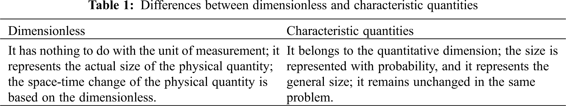
Theoretically, when the dynamic similarity of flow field is judged, the criterion is whether all corresponding points are equal in actual use, which will bring a lot of unnecessary trouble. In most cases, the point does not need to be all similar. Therefore, there is another judgment basis, that is, feature dimensionless number. Dimensionless is to remove a physical quantity with its corresponding characteristic quantity, and then the dimensionless of the physical quantity can be obtained. Tab. 1 shows the differences between dimensionless and characteristic quantities.
In this section, first, the performance of the new type of radial foil bearing at normal constant temperature is analyzed. When the static characteristics of the new type of radial foil bearing is solved, the non-dimensional modified Reynolds equation corresponding to the steady state is as follows:
where L is the bearing length, Cm is the velocity slip coefficient,
Because the above equation is a nonlinear equation, its exact solution cannot be solved. It is solved by the Newton-Raphson iterative method [17] and finite difference method [18]. First, the nonlinear function of
Newton-Raphson iterative method shows that:
After Newton iterative equation is obtained by substituting Eq. (4) into Eq. (6), the nonlinear function of gas film pressure is changed into a linear differential equation about pressure increment μ, which can greatly simplify the solution process. According to the finite difference method, the central difference scheme of the differential terms of pressure increment μ is defined as:
Then, according to Newton iterative equation, Eq. (7) can be rewritten as follows:
a and b represent the node numbers in the circumferential and axial directions. sa,b, da,b, ea,b, la,b, and na,b, represent the coefficient matrix. The expression of each differential term of lubrication film thickness and pressure are the same as those in Eq. (7).
After the initial values of pressure and film thickness are defined, the numerical solutions of pressure and film thickness can be obtained by iterative solution. The over relaxation iterative method is a new algorithm based on GS method, which uses weighted average to improve the convergence speed. When the gas film thickness distribution is updated iteratively, the over relaxation iteration method is used for weighted average. It can be obtained that:
where ψ represents the coefficient of over relaxation iteration and r represents the number of iteration steps. When the bearing lubrication problem is analyzed and solved, if the value range of ψ is [0,1], the convergence can be achieved.
Finally, the grid planning within the scope of calculation. When the bearing rotor asymmetry is not considered, the film thickness and pressure of the new foil bearing are based on the symmetry of the bearing cross-section. Therefore, the length of the half bearing can be taken to complete the analysis and calculation, which can be divided into uβ equal parts along the circumferential direction of bearing and divided into uκ equal parts in the axial direction. If the calculation range of bearing is [0: uβ,0: uκ+1], the corresponding solution range is [1: uβ-1,1: uκ].
(1) Boundary parameters. When the equation is solved, it is necessary to define the pressure boundary parameters of the bearing. For the new foil bearing, the environmental boundary parameters and symmetric boundary parameters are included. The flat foil of the bearing is not connected in a circle, so its fixed end and free end are communicated with the outside world. Moreover, the edge of the bearing is also connected to the outside world. Therefore, when the bearings are stacked along the middle section, the environmental boundary conditions of the new foil bearing are as follows:
According to the calculated values of bearing pressure and film thickness, the static performance such as the bearing capacity and viscous friction torque of the new foil bearing with micro grooves on the surface can be obtained by integrating.
(2) Static numerical solution. After the bearing structure parameters and operation parameters are specified, if the distribution of initial gas film pressure has been known, the pressure control Eq. (9) is substituted for the iterative solution of pressure increment. At the same time, the convergence degree of pressure increment is judged. The gas film pressure and thickness distribution are updated slowly, and the pressure convergence degree is further judged until there is no pressure increment and pressure convergence. Finally, the results of film thickness and pressure distribution are output to obtain the static bearing capacity and viscous friction torque of the new foil bearing.
2.4 Analysis of Solving Program
The proposed over relaxation iteration method and dimensionless equation are used to analyze the pressure distribution, load-carrying capacity and viscous friction torque of the new foil bearing at room temperature, the influence of the micro groove depth on the foil surface and the sliding effect of the friction pair, and the influence of the gas boundary on the static performance of the new foil bearing. Fig. 1 shows the solution framework as follows:
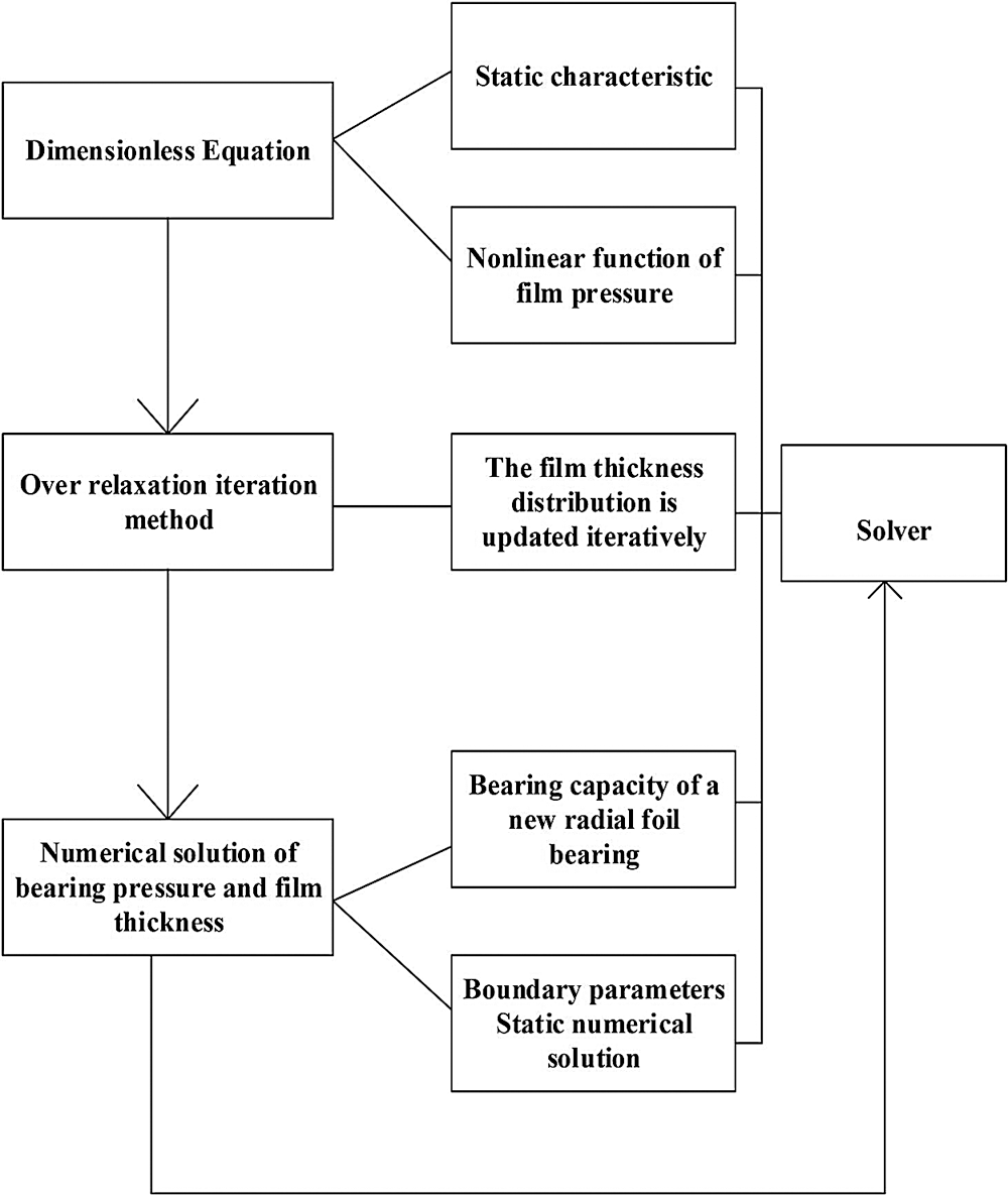
Figure 1: Solution program framework
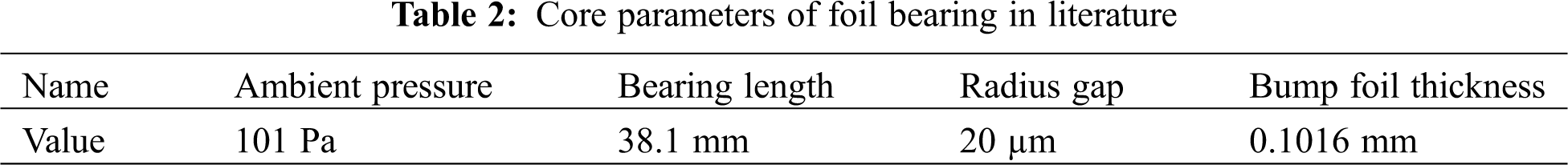
The experimental data in the NASA open literature are compared with the data of this exploration to determine the accuracy of the calculation process. For the foil bearing of bump type in the literature, the local deformation of bump foil will lead to larger contact area between bump foil and flat foil, and improve the stiffness of flat foil [19]. In the literature, the stiffness coefficient along the circumference of the flat foil is introduced to modify it. Among them, the value of the above tempering coefficient is clearly defined, so as to obtain the elastic modulus correction value of the flat foil along the circumferential direction, as shown in Tab. 2 below:
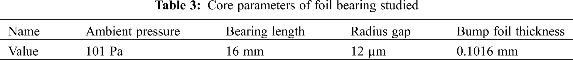
Tab. 3 shows the parameters of the new foil bearing.
According to the Iordanoff stiffness equation [20], the unit area stiffness of bump foil can be obtained, including: the unit area stiffness of bump foil with one end fixed and the other end free, the unit area stiffness of bump foil with two free ends, the tangential momentum coordination coefficient and the corresponding velocity slip coefficient.
However, the real radius clearance of the test bearing is not specified in the literature. In practice, the bearing is in a static state, and the foil structure and the bearing seat are all fitted, that is, there is a small initial clearance, which makes the radius clearance of foil bearing cannot be accurately predicted in general. In the actual operation process, with the increase of rotating speed, the gas dynamic pressure will increase slowly, and then push away the flat foil to make the flat foil fully fit with the bump foil and make the bump foil fully fit with the bearing pedestal. At this time, the clearance between the rotor and the flat foil is the radius clearance.
3.1 Accuracy of Calculation Program
The working speed of the bearing is set at 25000 r/min and 30000 r/min. Figs. 2 and 3 are the curves of the minimum gas film thickness at the middle section and edge of the bearing with the static load of the bearing.
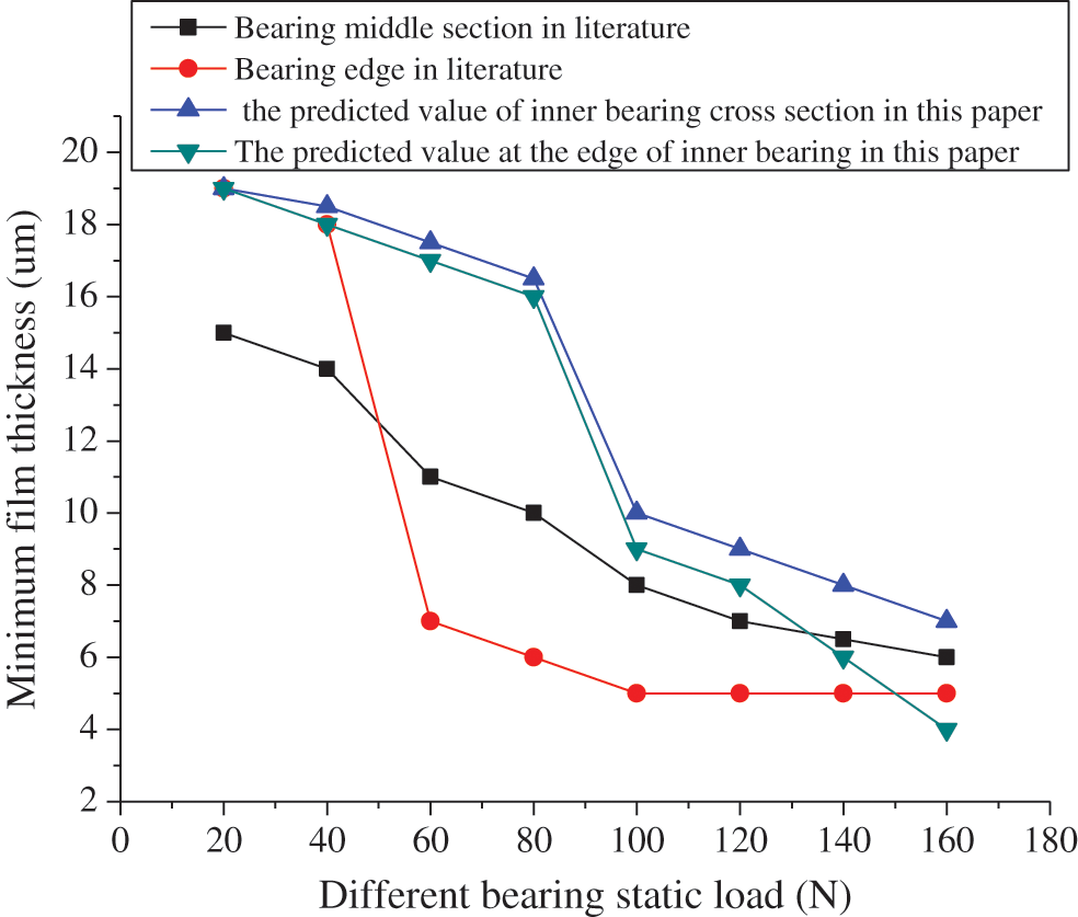
Figure 2: Variation of minimum gas film thickness at bearing middle section and edge with bearing static load (bearing working speed: 25000 r/min)
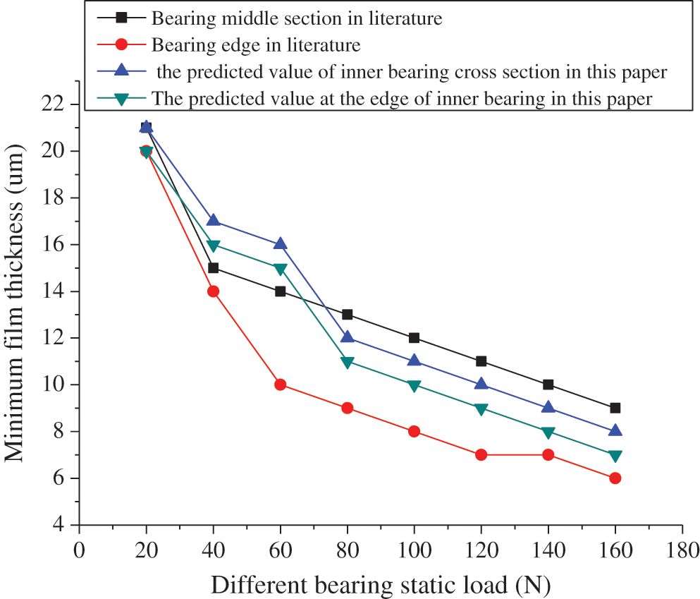
Figure 3: Variation of minimum gas film thickness at bearing middle section and edge with bearing static load (bearing working speed: 30000 r/min)
The simulation results of the rarefied gas model are compared with the experimental results in the literature. It suggests that when the working speed of the bearing is 25000 r/min, the minimum film thickness at the middle section and the edge of the bearing in NASA published literature decreases with the increase of the static load of the bearing. When the static load exceeds 40 N, the reduction rate of the minimum film thickness at the edge increases, which is quite different from the decrease of the middle section in the bearing. The minimum film thickness at the middle section and the edge of the bearing of this study also decreases with the increase of the bearing static load, but the reduction difference between the two is small.
During the operation of foil bearing, because the pressure level at the edge is always lower than that at the middle section, the film thickness at the edge is smaller than that at the middle section. Then, the simulation results of this study are compared with the experimental results of literature. The results suggest that under the same static load, the difference between the calculated minimum film thickness and the experimental results is not obvious. Moreover, with the increase of load, the simulation results are closer to the experimental values, which shows that the accuracy of the proposed calculation program is very high.
3.2 Influence of Gas Sliding Boundary on Bearing Force
The new foil bearing is symmetrical along the middle section of the bearing, so only half of the axial direction of the bearing is used to solve the static characteristics. In addition, the same meshing is used to solve the stiffness and pressure governing equations of the two-dimensional thick foil plate, and the number of elements in circumferential and axial direction is 70 × 16. Then, with the change of micro groove depth on the surface of flat foil, the influence of boundary slip effect on the new foil bearing force is shown in Fig. 4.
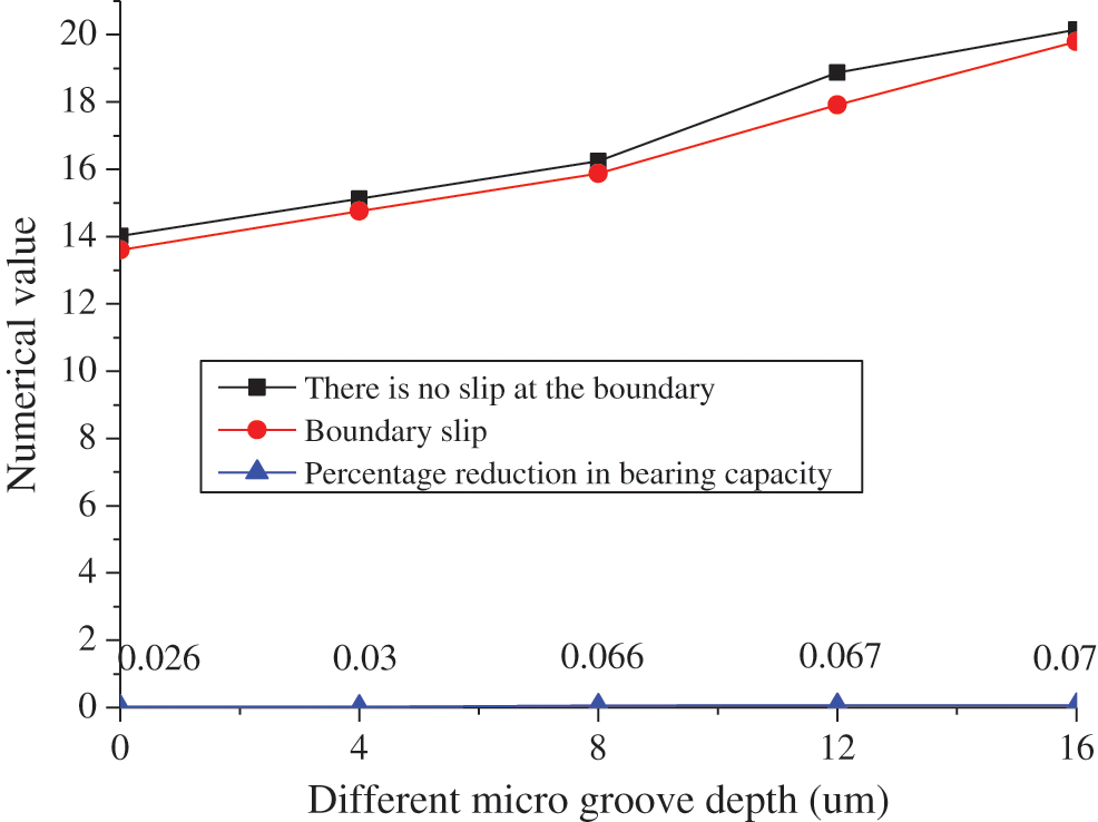
Figure 4: Effect of gas sliding boundary on bearing force (bearing rotor speed: 60000 r/min)
Fig. 4 shows that when the rotor speed of bearing is 60000 r/min, the bearing force will increase slowly with the increase of micro groove depth when there is no boundary slip and there is boundary slip, while the overall bearing force without boundary slip is slightly higher than that with boundary slip. At different micro groove depth, the percentage difference of bearing force reduction is small. It shows that for the new foil bearing with different depth of foil micro groove, the effect of boundary slip will also reduce the bearing capacity of foil bearing. With the increase of micro groove depth on the flat foil surface, the influence of boundary slip effect increases.
3.3 Effect of Gas Slip Boundary on Viscous Friction Torque
With the change of micro groove depth on the surface of flat foil, the influence of boundary slip effect on the viscous friction torque of the new type of radial foil bearing is shown in Fig. 5.
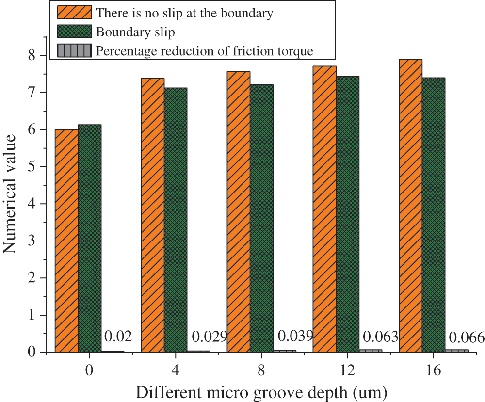
Figure 5: Effect of gas slip boundary on viscous friction torque (bearing rotor speed: 60000 r/min)
Fig. 5 reveals that when the eccentricity of the bearing increases, the thickness of the lubricating film along the eccentric direction decreases, and the convergence wedge effect of the dynamic pressure gas is strengthened, resulting in the increase of the gas pressure and the bearing capacity. The bearing capacity of the new radial foil bearing increases with the increase of the depth of the foil micro groove. Moreover, the larger the eccentricity is, the more significant the effect of bearing capacity increase is. When the eccentricity is 4 µm and the micro groove depth on the flat foil surface is 6 µm, the bearing capacity of the new foil bearing is about 13% higher than that of the traditional radial foil bearing.
3.4 Influence of Micro Groove Depth on Bearing Capacity of Flat Foil
When the working speed of the bearing is 60000 r/min, the variation curve of the bearing capacity of the new foil bearing with the depth of the micro groove on the foil surface under different eccentricities is shown in Fig. 6 below:
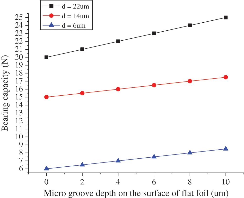
Figure 6: Effect of micro groove depth on bearing capacity of foil
Fig. 6 shows that when the rotor speed of bearing is 60000 r/min, the viscous friction torque increases slowly with the increase of micro groove depth without boundary slip. In the case of boundary slip, with the increase of micro groove depth, the change of viscous friction torque has no regularity. Before the micro groove depth is 4 µm, the viscous friction torque increases obviously, then decreases slightly, and then increases slightly, but the change gap is small. It suggests that for the new foil bearing with different depth of foil micro groove, the effect of boundary slip will also reduce the viscous friction torque of foil bearing. With the increase of micro groove depth on the flat foil surface, the influence of boundary slip effect increases.
3.5 Effect of Micro Groove Depth of the Surface of Flat Foil on Friction Torque of Bearing
When the working speed of the bearing is 60000 r/min, the variation curve of the bearing capacity of the new foil bearing with the micro groove depth on the foil surface under different eccentricities is shown in Fig. 7.
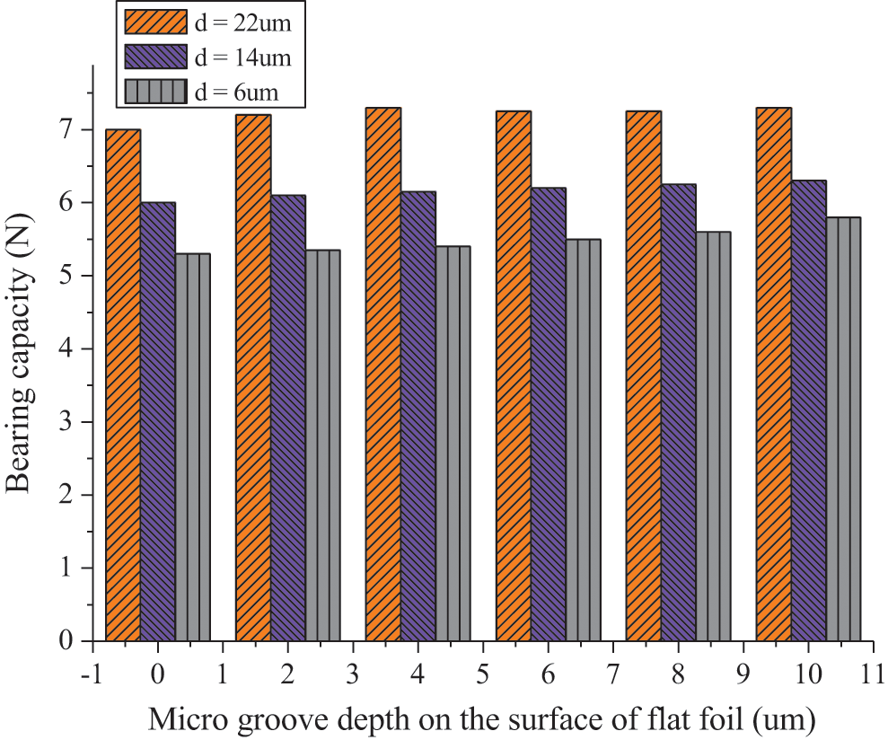
Figure 7: Effect of micro groove depth of the surface of flat foil on viscous friction torque of bearing
The expression of viscous friction torque reveals that its magnitude is not only related to the change rate of pressure along the circumferential direction, but also affected by the thickness of gas film, which leads to the complexity of its variation law. Fig. 6 shows that when the eccentricity is 6 µm and 14 µm, the viscous friction torque of the new foil bearing increases significantly with the increase of the foil groove depth. However, when the eccentricity is 22 µm, the viscous friction torque does not change with the depth of the foil groove. It suggests that with the increase of eccentricity, the influence of micro foil groove depth on the viscous friction torque of the new type of radial foil bearing is weakened. For the new foil bearing with an eccentricity of 14 µm and a micro groove depth of 8 µm, the viscous friction torque increases by about 7% compared with the traditional radial foil bearing.
The above results show that the bearing capacity and viscous friction moment of foil bearings decrease with the boundary slip effect of rarefied gas. The effect of boundary slip on the static performance of the bearing decreases with the increase of rotor speed. However, for the new foil bearing with surface micro grooves, the influence of boundary slip effect is limited by the depth of foil groove. Therefore, it is necessary to consider the influence of boundary slip effect in the follow-up study.
In order to improve the bearing capacity and performance of foil bearing, the new foil bearing with surface microstructure is taken as the experimental object. The middle range of the flat foil includes micro grooves along the circumference, and the depth of the grooves is micron level. In order to solve the problem of gas rarefaction in the new foil bearing, the governing equation of lubrication gas pressure based on boundary velocity slip is established. The pressure distribution, bearing capacity and viscous friction torque of the new foil bearing at room temperature, as well as the influence of the micro groove depth on the surface of the foil and the gas boundary slip effect on the static performance of the new foil bearing are analyzed. It suggests that when the working speed of the bearing is 25000 r/min, the minimum film thickness at the middle section and the edge of the bearing in NASA published literature decreases with the increase of the static load of the bearing. When the static load exceeds 40 N, the reduction rate of the minimum film thickness at the edge increases, which is quite different from the decrease of the middle section in the bearing. The minimum film thickness at the middle section and the edge of the bearing of this study also decreases with the increase of the bearing static load, but the reduction difference between the two is small. When the rotor speed of the bearing is 60000 r/min, the bearing force increases slowly with the increase of the micro groove depth when there is no boundary slip or boundary slip, and the overall bearing force when there is no boundary slip is slightly higher than that when there is boundary slip. When the rotor speed of bearing is 60000 r/min, the viscous friction torque increases slowly with the increase of micro groove depth without boundary slip. In the case of boundary slip, with the increase of micro groove depth, the viscous friction torque increases significantly before the micro groove depth is 4 µm, and there is little change in the later change. In other words, compared with the traditional radial foil bearing, the film thickness in the middle section of the new foil bearing is increased, and the film thickness at both ends is decreased, which greatly reduces the leakage of lubricating gas from the end, promotes the hydrodynamic effect, and finally enhances the bearing capacity. At the same time, the boundary slip effect of rarefied gas will reduce the bearing capacity and viscous friction torque. The influence of gas boundary slip effect increases with the depth of the foil micro groove. Due to time and personal reasons, there are some deficiencies. The influence of micro groove depth of the surface of flat foil and gas boundary slip effect of on the dynamic performance of the new foil bearing is not analyzed, which will affect the preciseness of the research results. This part is also the focus of follow-up research.
Acknowledgement: The authors are grateful to our friends for proofreading this manuscript.
Funding Statement: The authors received no specific funding for this study.
Conflicts of Interest: The authors declare that they have no conflicts of interest to report regarding the present study.
1. Zhao, X., Jia, M. (2019). A new local-global deep neural network and its application in rotating machinery fault diagnosis. Neurocomputing, 366, 215–233. [Google Scholar]
2. Long, K. W., Guang, F. B., Xue, J. L., Ding, Q. L. (2016). Effects of unbalance location on dynamic characteristics of high-speed gasoline engine turbocharger with floating ring bearings. Chinese Journal of Mechanical Engineering, 29(2), 271–280. [Google Scholar]
3. Zhang, X., Gu, X. (2017). Effect of misaligned bearing support performance on natural frequencies of marine propulsion shafting. Journal of Vibroengineering, 19(3), 1854–1866. [Google Scholar]
4. Zhang, J. Y., Zhao, X. R., Chang, H. P., Fang, H. (2018). Effects of sliding boundary on static characteristics of aerodynamic compliant foil bearing. Tuijin Jishu/Journal of Propulsion Technology, 39(2), 388–395. [Google Scholar]
5. Sytin, A., Rodichev, A., Tyurin, V. (2017). Characteristics of dynamic analysis of rotors in foil bearings with the bump foil. Procedia Engineering, 39(2), 134–139. [Google Scholar]
6. Mcvicar, J. J., Lavroff, J., Davis, M. R., Thomas, G. (2015). Effect of slam force duration on the vibratory response of a lightweight high-speed wave-piercing catamaran. Journal of Ship Research, 59(2), 69–84. [Google Scholar]
7. Edrah, M., Lo, K. L., Anaya, L. O. (2015). Impacts of high penetration of DFIG wind turbines on rotor angle stability of power systems. IEEE Transactions on Sustainable Energy, 6(3), 759–766. [Google Scholar]
8. Polyakov, R., Bondarenko, M., Savin, L. (2015). Hybrid bearing with actively adjustable radial gap of gas foil bearing. Procedia Engineering, 6(3), 132–140. [Google Scholar]
9. Wu, Y., Yang, L., Xu, T., Xu, H. (2019). Combined effect of rarefaction and effective viscosity on micro-elasto-aerodynamic lubrication performance of gas microbearings. Micromachines, 6(3), 657. [Google Scholar]
10. Feng, K., Deng, Z., Zhao, X., Li, W., Guo, Z. (2017). Test on static and temperature characteristics of gas foil bearing. Hangkong Dongli Xuebao/Journal of Aerospace Power, 32(6), 1394–1399. [Google Scholar]
11. Sam, S. H. (2017). Renault previews F1’s connected future. Autocar: Frist for New Cars, 292(4), 13. [Google Scholar]
12. Gribinichenko, M. V., Kurenskii, A. V., Kutsenko, N. V. (2016). Hybrid foil bearing with gas lubrication. Russian Engineering Research, 36(3), 198–200. [Google Scholar]
13. Rehab, I., Tian, X., Zhang, R., Gu, F., Ball, A. (2017). A study of the diagnostic amplitude of rolling bearing under increasing radial clearance using modulation signal bispectrum. International Journal of Comadem, 20(3), 39–43. [Google Scholar]
14. Yassin, Y. A., Abbas, M. Q., Alwan, T. H. (2020). Effect of change slot orifice width on flux density and performance for three phase linear induction motor using Ansys Maxwell. Technology Reports of Kansai University, 62(3), 11. [Google Scholar]
15. Żywica, G., Bagiński, P., Breńkacz, Ł., Miąskowski, W., Pietkiewicz, P. et al. (2017). Dynamic state assessment of the high-speed rotor based on a structural-flow model of a foil bearing. Diagnostyka, 18(1), 95–102. [Google Scholar]
16. Brusniak, L., Dolling, D. S. (2015). Engineering estimation of fluctuating loads in shock wave/turbulent boundary-layer interactions. AIAA Journal, 34(12), 2554–2561. [Google Scholar]
17. Jankovic, S., Ivanovic, B. (2015). Application of combined Newton-Raphson method to large load flow models. Electric Power Systems Research, 127(10), 134–140. [Google Scholar]
18. Shabani, B., Lavroff, J., Holloway, D. S., Michael, R. D., Giles, A. T. (2019). Wet-deck slamming loads and pressures acting on wave piercing catamarans. International Shipbuilding Progress, 66(3), 201–231. [Google Scholar]
19. Boudreau, M., Picard, D. M., Dumas, G. (2020). A parametric study and optimization of the fully-passive flapping-foil turbine at high Reynolds number. Renewable Energy, 146(2), 1958–1975. [Google Scholar]
20. Zied, K., Al-Grafi, M. (2015). Design of auxetic sandwich panel faceplates comprising cellular networks with high stiffness and negative Poisson’s ratio. Advanced Composite Materials, 24(1), 175–196. [Google Scholar]
 | This work is licensed under a Creative Commons Attribution 4.0 International License, which permits unrestricted use, distribution, and reproduction in any medium, provided the original work is properly cited. |