| Fluid Dynamics & Materials Processing |
DOI: 10.32604/fdmp.2021.016283
ARTICLE
Experimental and Numerical Analysis of High-Strength Concrete Beams Including Steel Fibers and Large-Particle Recycled Coarse Aggregates
1Department of Civil Engineering, Shandong Jianzhu University, Jinan, 250101, China
2Key Laboratory of Building Structural Retrofitting and Underground Space Engineering, Shandong Jianzhu University, Ministry of Education, Jinan, 250101, China
3Beijing Key Laboratory of Earthquake Engineering and Structural Retrofit, Beijing University of Technology, Beijing, 100124, China
*Corresponding Author: Chunyang Liu. Email: liucy2011@sdjzu.edu.cn
Received: 23 February 2021; Accepted: 29 April 2021
Abstract: In order to study the performances of high-strength concrete beams including steel fibers and large-particle recycled aggregates, four different beams have been designed, tested experimentally and simulated numerically. As varying parameters, the replacement rates of recycled coarse aggregates and CFRP (carbon fiber reinforced polymer) sheets have been considered. The failure mode of these beams, related load deflection curves, stirrup strain and shear capacity have been determined through monotonic loading tests. The simulations have been conducted using the ABAQUS finite element software. The results show that the shear failure mode of recycled concrete beams is similar to that of ordinary concrete beams. The shear carrying capacity of high-strength concrete beams including steel fibers and large-particle recycled coarse aggregates grows with an increase in the replacement rate of recycled coarse aggregates. Reinforcement with CFRP sheets can significantly improve the beam’s shear carrying capacity and overall resistance to deformation.
Keywords: High-strength recycled concrete beam; steel fiber; large-particle recycled aggregates; pre-damage reinforcement; numerical simulation; carrying capacity calculation
Presently, the problems associated with the appropriate utilization of the construction waste and the existing resources should be considered at priority and the rough production model must be changed. The effective use of recycled concrete has been able to minimize the damage caused to the environment caused by the dumping of construction waste, and thus, the pressure on living space has been relieved. To achieve this, a series of experimental studies on recycled concrete mixtures, their basic properties, performances, and modification techniques have been performed [1–9]. Currently research on high-strength recycled concrete is a key concern. Cao et al. [10] experimentally fitted stress-strain curves for high-strength recycled concrete with different recycled coarse aggregate replacement rates. Gonzalez et al. [11] carried out a shear test on recycled concrete beams and found that the ultimate load capacity of recycled concrete beams with more than 50% replacement of recycled coarse aggregates was reduced by about 10%–20%. Luo [12] carried out a four-point stress test on beams of equal height and variable width. The equations for the shear carrying capacity of the diagonal section of recycled concrete beams with different recycled aggregate replacements percentage were mentioned. The results of the study conducted by Wu et al. [13] showed that the shear carrying capacity of recycled concrete beams increased with the increase in the stirrup ratio, and gradually decreased with the increase of the shear span ratio and the replacement percentage of recycled coarse aggregate. Li et al. [14] analyzed theoretically, experimentally and microscopically the intrinsic structure curves of the recycled concrete including iron ore tailings (IOT) before and after carbonation. The study showed that the comprehensive damage parameter of recycled concrete was minimized at 30% IOT content, indicating that IOT had a better optimization effect on the intrinsic constitutive curve of RAC. Long et al. [15] experimentally evaluated the related surplus coefficient (defined as the proportionality factor linking the measured compressive strength value of the cement after 28 days to the “standard” value of cement strength) associated with different sources of P.O42.5 cement. The results shown that the related surplus coefficient of cement strength could be 1.16. This laid the foundation for reducing production costs and improving the performance of commercial concrete.
CFRP cloth (Carbon fiber reinforced polymer sheet) is a material with high strength and high modulus of elasticity material and has been widely used in the field of civil engineering. Mosallam et al. [16] investigated the shear performance of nine concrete beams reinforced with CFRP sheets and concluded that CFRP sheet reinforced concrete beams could effectively improve the ultimate shear load capacity of the beams. In addition, the shear span ratio had a large effect on the ultimate shear load capacity of the reinforced beams. Cheng et al. [17] studied the shear performance of the concrete beams reinforced with CFRP sheet under load condition and established the equation of shear bearing capacity of the inclined section of beams using finite element analysis, which showed that the ultimate shear bearing capacity of the inclined section of beams could be significantly improved by using prestressed CFRP sheet reinforcement.
It has been shown that coarse aggregates of large particle size could play a supporting role as a skeleton inside the concrete, thus increasing the compressive strength of recycled concrete [18]. In the present work, four high-strength concrete beams including steel fibers and large-particle recycled aggregates were designed. The replacement rates of recycled coarse aggregates and CFRP sheets were studied in detail. Monotonic loading tests were used to analyze the failure mode, load-deflection curves, stirrup strain and shear capacity of the beams. Test results were then compared with the by ABAQUS simulation results. The objective of this study was to recommend the application of recycled concrete in structural engineering.
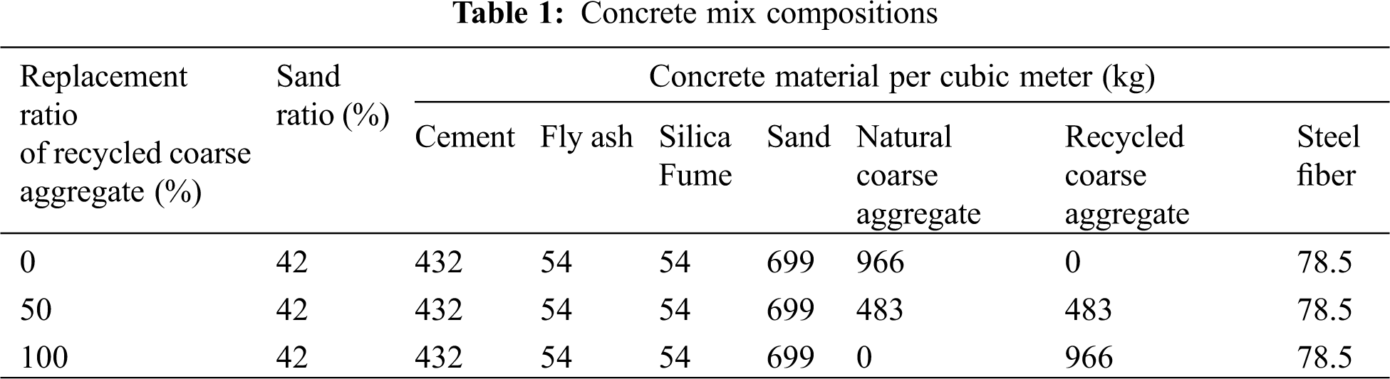
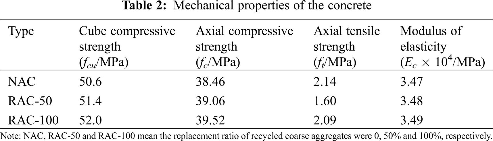
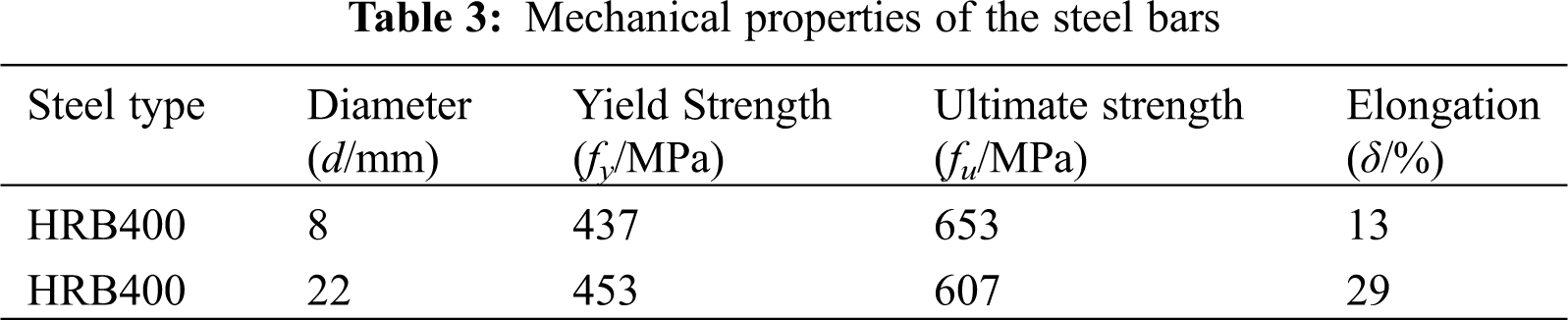
The ordinary Portland cement with a strength grade of 42.5 and natural river sand as a fine aggregate were used for the experiments. Coarse aggregates were natural and ordinary coarse aggregates. Natural coarse aggregate was made of common gravel, with a maximum particle size of 31.5 mm. Recycled coarse aggregate was made from concrete after the demolition of an abandoned building. Impurities such as glass and wood chips were manually removed, and the particle size ranged from 31.5 mm to 60 mm. Fibers of length 13 mm and the length-to-diameter ratio of 65 were made from high-strength steel fibers with a copper-plated surface. Tab. 1 shows the composition of recycled concrete mix. The grade of steel bars used in the specimens was HRB 400. The mechanical properties of the experimentally measured concrete and reinforcement material are shown in Tabs. 2 and 3.
A total of four specimens were designed and manufactured for the present experimental study, including three recycled concrete beams and one reference beam of ordinary concrete. The number and design parameters of the test specimens are shown in Tab. 4. The specimens were 2400 mm long with an effective length of 2100 mm. The width and depth of all test beams were 200 mm and 400 mm, respectively. Also, the thickness of the protective layer was 15 mm. Three 22 mm steel bars were used as the bottom reinforcement of the specimen beams and two 8 mm steel bars were used for the top reinforcement. All steel stirrups were 8 mm in diameter, spaced 200 mm apart, and evenly spaced along the length of the beam. The design details of the specimens are shown in Fig. 1.
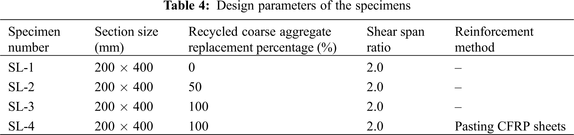
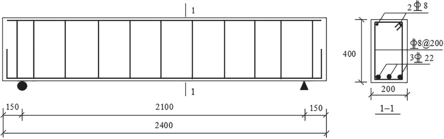
Figure 1: Schematic for specimen design
2.3 Point Arrangement and Reinforcement Scheme Measurement
Four resistance strain gauges were attached to the steel stirrups at different locations to measure the strain and were placed to measure the displacement of the specimens at the loading point, mid-span, and at the two supports. The specific positions of the CFRP sheets as per the requirements of technical specification for strengthening concrete structures with CFRP and the specific conditions of the test site are shown in Fig. 2. The bottom of the specimens were reinforced with CFRP sheet to increase the flexural capacity of the specimens and to ensure that the expected test results are achieved. After the specimen SL-4 was pre-damaged, the CFRP sheet was applied to the shear zones near the loading point for shear reinforcement. The single-layered and 100 mm wide CFRP sheet strip was spaced 200 mm apart. The reinforcement position of CFRP sheets is shown in Fig. 3.
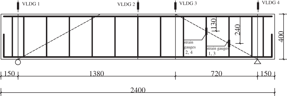
Figure 2: Layout of stirrup strain gauges
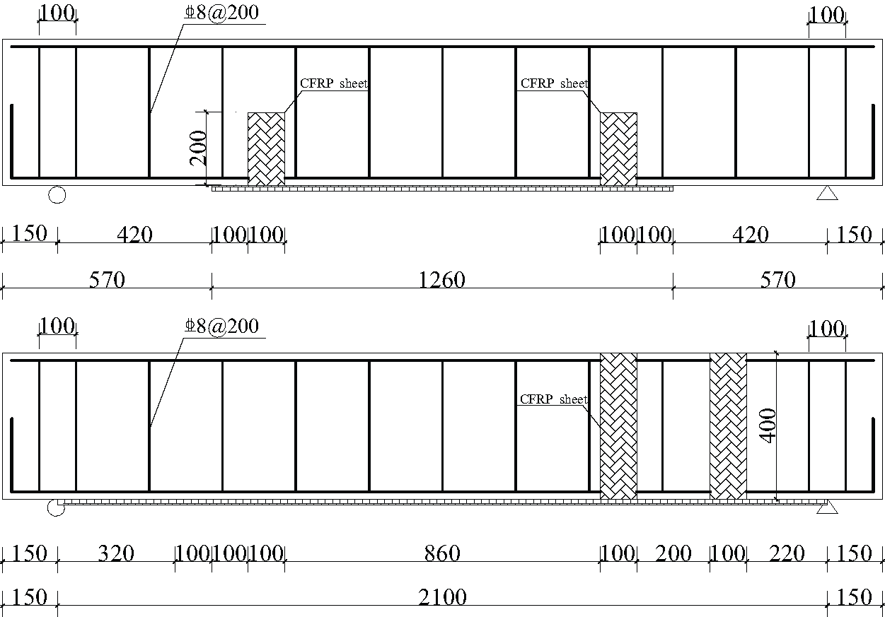
Figure 3: Schematic depicting the CFRP sheets reinforcement position. (a) Layout of CFRP sheets in specimen SL-1~SL-3 (b) Reinforcement position of CFRP sheets in specimen SL-4
2.4 Loading System and Equipment
During the experiments, monotonic and gradual loading processes were carried out by hydraulic jacks. The initial load increments of specimens SL-1 to SL-3 were 20 kN and were changed to 40 kN after the appearance of the first oblique crack. The time interval of each loading was 3 min, which was used to record the data and observe the development of cracks. Specimen SL-4 was loaded to 0.9 times the peak load of specimen L-3 and then the loading was stopped. At this point, the critical diagonal crack width of the specimen was 2 mm and the steel stirrups strain was about 80% of the yield strain. The specimen SL-4 was reinforced by CFRP sheets and loaded again.
The shear failure mode occurred in all the specimens and the corresponding failure modes of the specimens SL-1 to SL-3 are shown in Fig. 4. In the case of specimen SL-1, when a load of 150 kN was applied, small curved vertical cracks began to appear below the loading point. When the applied load was increased to 200 kN, multiple oblique shear cracks appeared in the shear zones of the specimen. The number of diagonal cracks increased and extended towards the loading point during continuous application of the load. At the same time, the vertical cracks developed into bending shear cracks. When a load of 300 kN was applied, the vertical cracks did not develop any longer, and one of the diagonal cracks widened rapidly. On further increasing the load to 460 kN, the diagonal crack penetrated the beam and transformed into a critical crack. Consequently, the concrete below the loading point of the specimen was crushed and the specimen was destroyed. While, in the case of specimen SL-2, the first diagonal crack formed at the application of a load equal to 150 kN. When the applied load was 400 kN, a 2 mm wide diagonal crack developed rapidly. On further increasing to the 500 kN, critical diagonal cracks were formed in the shear zones of the specimen, thereby destroying the specimen. In the case of the specimen SL-3, a diagonal crack appeared in the shear-span zone when a load of 200 kN was applied. Further, the application of an increased load of 350 kN, developed a diagonal crack rapidly upward to the loading point. Also, a critical diagonal crack appeared when the applied load was 500 kN. At this point, the vertical CFRP sheet was peeled off causing permanent damage to the specimen.
The damaged pattern of specimen SL-4 before and after pre-damage reinforcement is shown in Fig. 5. During pre-damage, many vertical cracks were formed below the loading point at the initial loading stage. Diagonal cracks also appeared near the support when a load of 180 kN was applied. When the load further increased to 450 kN, the diagonal crack widened rapidly. Moreover, the maximum width of the oblique crack became 2 mm, and the experiment was stopped. The specimen was reinforced and the load was applied again. The damaged pattern of the specimen is shown in Fig. 5b. At the initial loading stage, the development equal to cracks in SL-4 was not significantly different from other specimens. The application of a load of 350 kN resulted in the formation of longer and wider diagonal cracks, while the vertical CFRP sheet was peeled off from the surface of the specimen. When the applied load was increased to 540 kN, the CFRP sheet intersecting the oblique main crack was fractured, and the one at the bottom of the beam was peeled off, thereby, thereby damaging the specimen.
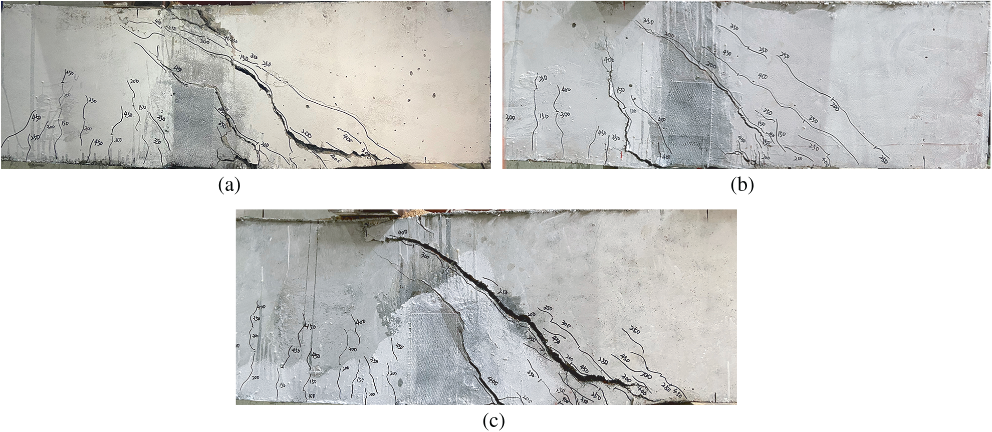
Figure 4: Crack pattern of specimen SL-1~SL-3. (a) SL-1 (b) SL-2 (c) SL-3
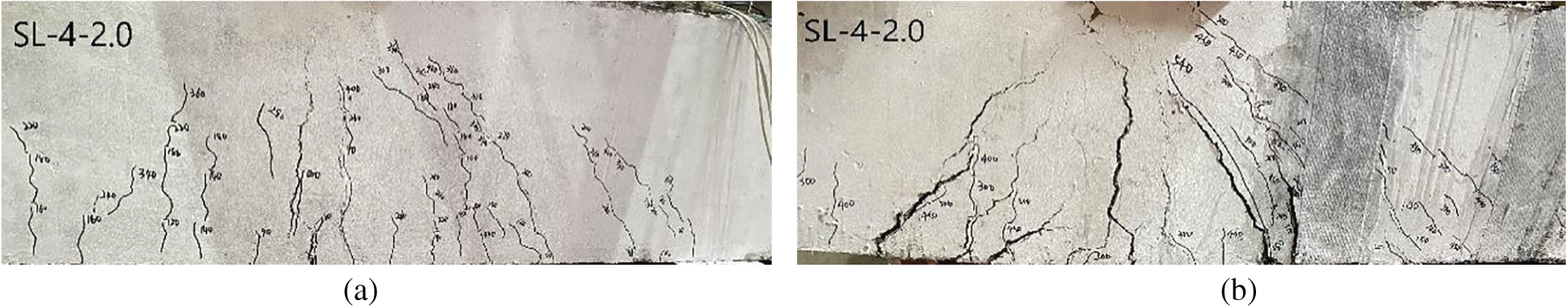
Figure 5: Crack pattern of specimen SL-4 before and after pre-damage reinforcement. (a) Before pre-damage reinforcement (b) After pre-damage reinforcement
The load-deflection curves of SL-1, SL-2, and SL-3 are shown in Fig. 6a. The results showed that the slope of specimen SL-1 was significantly steeper than that of specimens SL-2 and SL-3 at the initial loading stage. This implied that the stiffness of ordinary reinforced concrete beams was higher than that of the recycled concrete beams. However, the slope of the curve of each specimen was approximately the same before the applied load reached the peak value. At this point, the skeleton support role of the large-sized recycled coarse aggregates was advantageous. Therefore, the difference between the stiffness of specimens SL-1, SL-2, and SL-3 was not significant. The peak load of the specimen SL-1 was 466 kN, and the corresponding deflection value was 14.55 mm. In comparison with the specimen SL-1, the peak load of SL-2 and SL-3 was increased by about 2.1% (476 kN) and 4.3% (490 kN), respectively. This indicated that the increase in the replacement rates of recycled coarse aggregate improved the shear carrying capacity of the specimens to some extent. The deflections at peak load of the specimen SL-2 (12.43 mm) and SL-3 (11.50 mm) were relatively close to that of the specimen SL-1, suggesting that the specimens had good resistance to deformation.
Fig. 6b compared the load-deflection curves of specimens SL-3 and SL-4. The stiffness of the specimen SL-4 was lower than that of SL-3 at the initial loading stage. This was ascribed to high the failure degree of specimen SL-4 after pre-damage, thus, reducing the specimen stiffness and poor ductility. The continuous load application made the vertical CFRP sheet resist the tensile force. As a result, the stiffness of the test piece gradually increased, and the overall resistance to deformation was also enhanced. When compared with the specimen SL-3, the peak load of specimen SL-4 was increased by about 8.9% and the peak displacement was reduced by 10.6%. This indicated that CFRP sheet reinforcement could improve the shear carrying capacity of the specimen as well as the resistance to deformation.
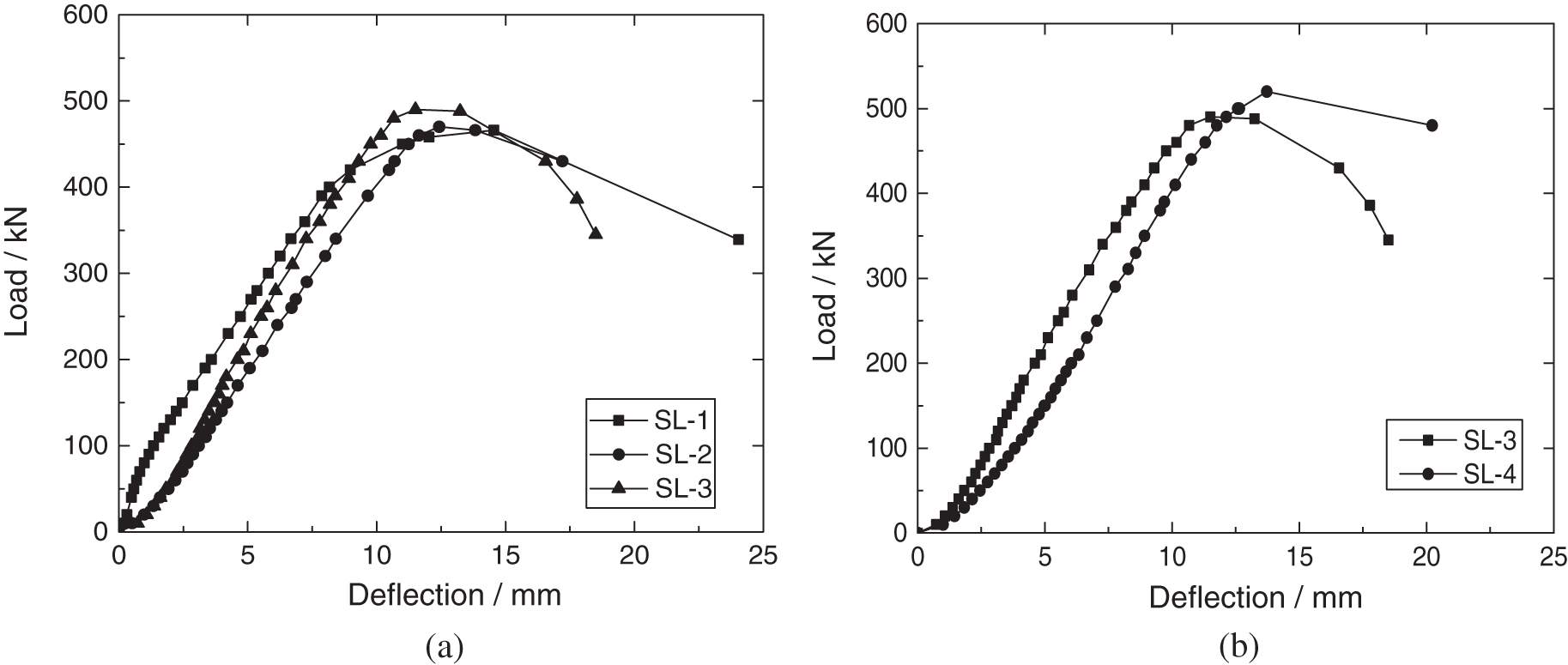
Figure 6: Load–displacement curves of specimens under different conditions. (a) Recycled coarse aggregate replacement percentage (b) Pre-damage reinforcement
3.3 Load-strain Curve of Stirrups
The load-strain curves of the stirrups in the shear zones of each specimen are shown in Fig. 7. At the initial loading stage, the strain of the specimens increased slowly and almost linearly. After the appearance of cracks in the concrete in the shear zone, the stirrups began to bear the stress. At this point, the slope of the curve was smaller, and the strain increased rapidly. The strain of the stirrups near the support of the specimen was significantly smaller than the ones near the loading point. Especially at the peak load, the strain at the loading point of the specimens SL-1 and SL-2 were 3068.4 με and 2234.8 με, respectively, higher than those near the support. This indicated that the stirrups near the loading point bore more tensile stress, and none of the stirrup strains reached the ultimate strain when the specimen SL-4 was damaged. This was because the CFRP sheet bore the shear force instead of the stirrups after the diagonal cracks were generated. As a result, the CFRP sheet spalled off from the concrete surface at the time of the damage, and the stirrups did not form.
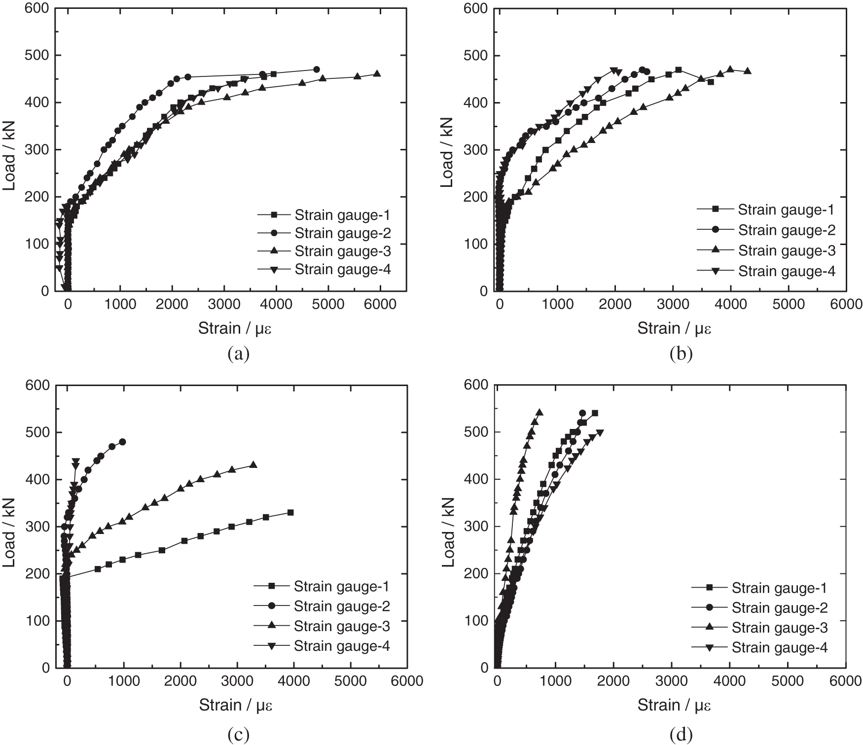
Figure 7: The load-strain curve of the stirrup of specimens. (a) SL-1 (b) SL-2 (c) SL-3 (d) SL-4
In the present work, the concrete damage plastic (CDP) model was used for finite element analysis. The constitutive relation of compressive stress-strain of high strength recycled concrete was based on the formula proposed in the literature [10]. The ideal elastic-plastic model was chosen for the steel bars. The stress-strain relationship of the CFRP sheet had linear elasticity, and was considered damaged when the force exceeded the ultimate tensile strength. While imposing the boundary conditions, the displacement and rotation constraints in the three directions were applied to the right side support of the specimens. Displacement constraints in y and z directions and rotation constraints in three directions were applied to the left end of the specimen. The mesh division of concrete and CFRP sheets of the specimen is shown in Fig. 8.
When the specimen SL-4 was loaded, the CFRP sheet was set to a failure state in the first stage. At this point, the CFRP sheets were not working. Once the applied load reached the target value, the CFRP sheet was set to the active state in the second stage, while the CFRP sheet and concrete beams worked together to bear external forces until the specimens were destroyed.
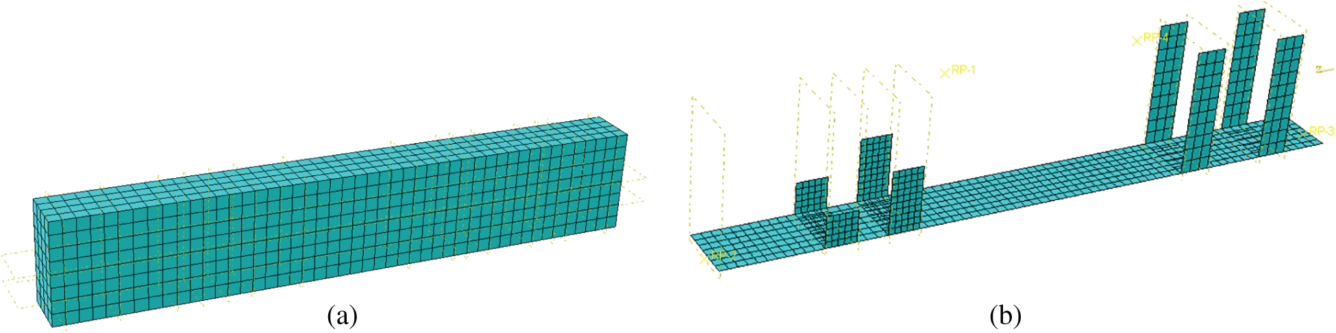
Figure 8: Mesh division of concrete and CFRP sheets. (a) Mesh division of concrete (b) Mesh division of CFRP sheets
The equivalent plastic strain of concrete when the specimen was damaged is shown in Fig. 9. It could be seen that the stress in the region between the loading point and the support was large, which was typical of a shear failure. Also, the results were in good agreement with the finite element simulation results. The simulated values of the deflection compared with the measured values shown in Fig. 10. Indicated that the development trends of the two curves were similar. In the initial loading stage, the slope of the curve was steeper, however, with the continuous application of load, it was reduced along with the stiffness. When the same load was applied, the simulated deflection values were slightly higher than the measured values, and the peak loads were lower than the measured values, about 97.0%, 97.0%, 97.8%, and 93.1% of the measured values, respectively in all the samples. The finite element simulation results and the experimental data, altogether confirmed that the parameter setting was reasonable and the model was effective.
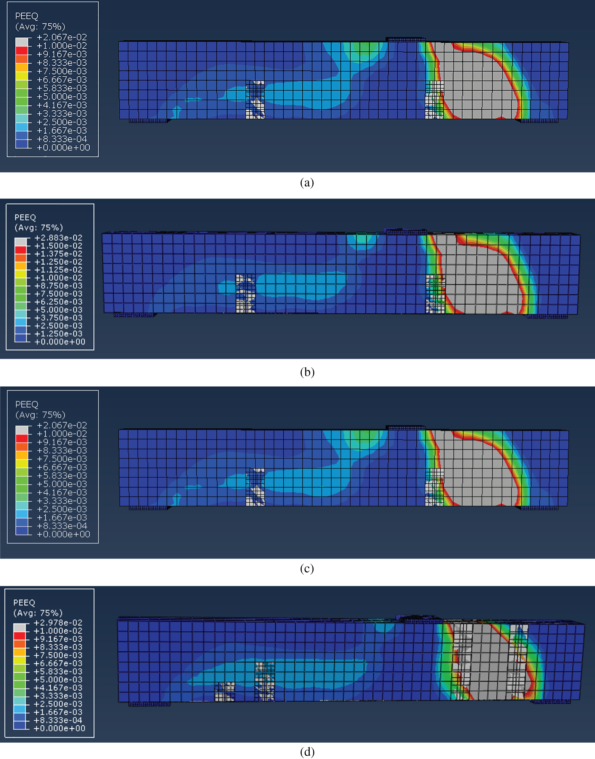
Figure 9: Equivalent plastic strain of the specimens. (a) Equivalent plastic strain of SL-3 concrete (b) Equivalent plastic strain of SL-2 concrete (c) Equivalent plastic strain of SL-3 concrete (d) Equivalent plastic strain of SL-4 concrete
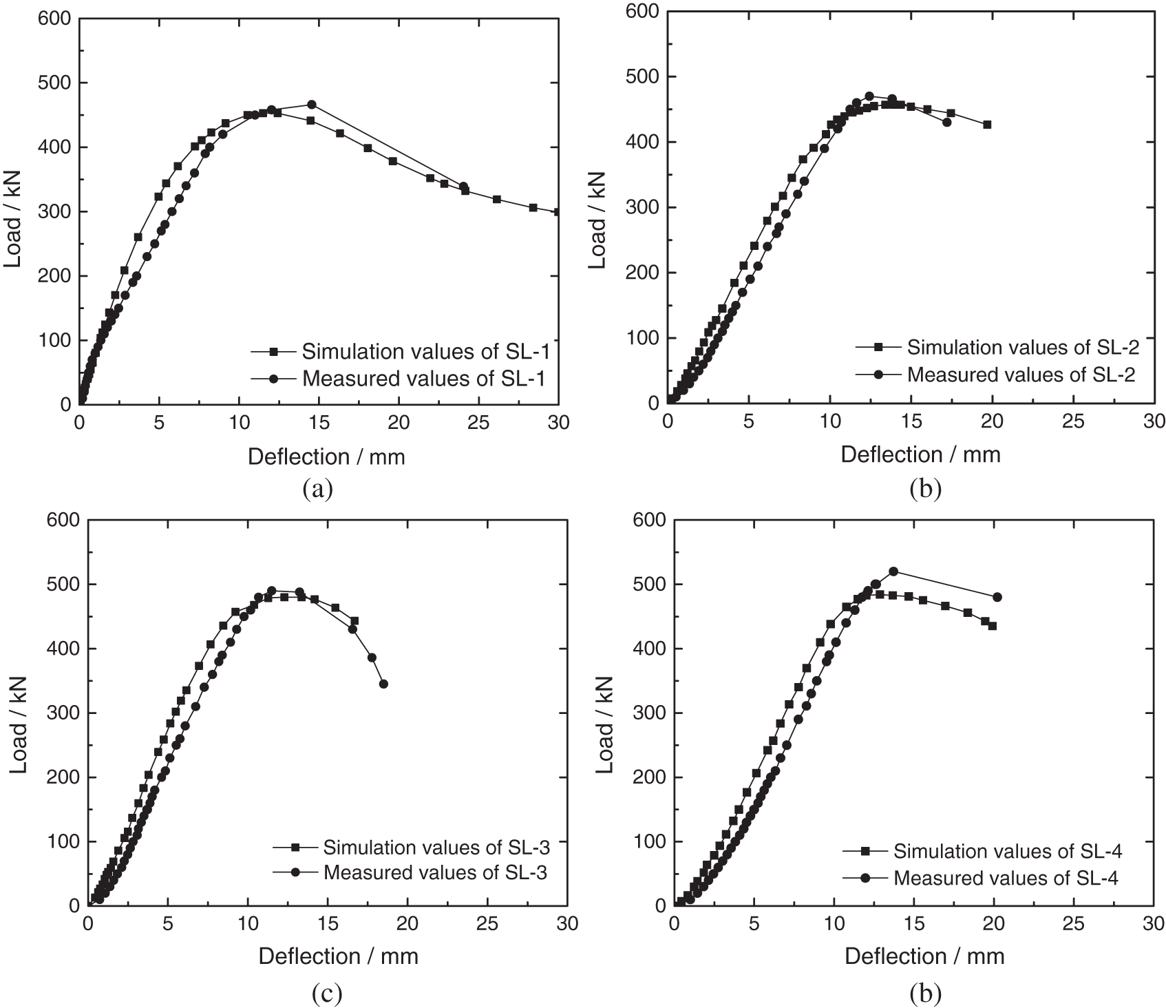
Figure 10: Comparison between the simulated and measured deflections of the specimens. (a) SL-1 (b) SL-2 (c) SL-3 (d) SL-4
5 Calculation of Shear Carrying Capacity
The present study focused on calculating the bearing capacity of ordinary concrete beams proposed in the relevant codes. The analysis was carried out by combining the characteristics of the recycled concrete and relevant experimental data. The equation for calculating the shear carrying capacity of high-strength concrete beams including steel fibers and large-particle recycled aggregates under different recycled coarse aggregate replacement rates was discussed. The force state of the specimens at the peak point was used as a reference to calculate shear carrying capacity.
The shear carrying capacity of ordinary concrete beams under concentrated load could be obtained by Eq. (1).
where Vcs is the shear carrying capacity of the inclined section, λ is the shear span ratio, ft is the designed value of concrete axial tensile strength, b is the specimen section width, s is the spacing of stirrups, Asv is the total cross-sectional area of each leg of the stirrup in the same section, fyv is the designed value of stirrup tensile strength, h0 is the effective height of specimen section.
The shear carrying capacity of recycled concrete beams was higher than that of ordinary concrete beams. Therefore, the shear carrying capacity of recycled concrete beams was modified as Eq. (2).
where r is the replacement rates of recycled coarse aggregate, a is the correction factor. The measured values of recycled concrete beams at different replacement rates were substituted into Eq. (2). According to the regression analysis and the safety of the recycled concrete beams, the value of a was taken as 0.2. The equation for high-strength concrete beams including steel fibers and large-particle recycled aggregates is as follows:
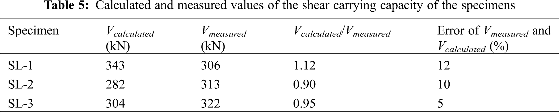
The relevant data obtained from the experimental conducted in this study were substituted into Eq. (3). The calculated values and the measured values obtained from the experimental results are listed in Tab. 5, where Vcalculate is the value calculated by Eq. (3), and Vmeasured is the shear carrying capacity at the loading point calculated according to the test value. It could be seen from Tab. 5 that the calculated values were nearly the same as the experimental results with relatively small errors. Hence, the above equation was suitable for the calculation of the shear carrying capacity of the specimens.
In summary, the shear properties of four high-strength concrete beams including steel fibers and large-particle recycled aggregates were investigated. The results showed that the shear failure mechanism of high-strength recycled concrete beams including steel fibers and large particle size coarse aggregate was similar to that of the ordinary concrete beams. With the increase in the replacement rate of the recycled coarse aggregate, the shear carrying capacity of high-strength recycled concrete beams including steel fibers and large particle size coarse aggregates was also improved, and the deformation resistance was similar to that of the ordinary concrete beams. In comparison to with the specimens without reinforcement, the deflection of the reinforced recycled concrete beams at the loading point was reduced and the peak load capacity was increased. Moreover, the finite element simulation results were consistent with the experimental results, thereby, validating the set parameters used in the study. The difference in the shear behavior of recycled high-strength recycled concrete beams including steel fibers and large particle size coarse aggregates under different factors could be simulated. Our method showed a potential application for the designing of materials for their effective and practical utilization.
Acknowledgement: My gratitude would go to my dear family for their love and support throughout the years. I would also like to express my sincere gratitude to my supervisors and classmates for their help and understanding during the experimental process of my thesis and for helping me to solve my difficulties.
Funding Statement: This work was supported by the Natural Science Foundation of Shandong Province [Grant Nos. ZR2015EQ017, ZR2018MEE044] and the Key Laboratory Open Project of the Ministry of Education of Beijing University of Technology [Grant No. 2020B03].
Conflicts of Interest: The authors declare that they have no conflicts of interest to report regarding the present study.
1. Xu, F. W., Tian, B., Xu, G. (2020). Quantitative analysis of interface transition zone of recycled concrete. Yangtze River, 51(10), 177–181. [Google Scholar]
2. Liu, Q., Xiao, J. Z., Zhi, X., Wang, Z. J. (2020). Damage evolution study of modeled recycled concrete based on orientation of recycled aggregate. Journal of Tongji University (Natural Science), 48(10), 1417–1424. [Google Scholar]
3. Wu, Y. P., Jian, L., Zhang, X., Wang, Y. G. (2020). Research on impact resistance and impermeability of high-volume fly ash recycled aggregate concrete after exposure to high temperature. Journal Building Structures, 1–10. DOI 10.14006/j.jzjgxb.2020.0350. [Google Scholar] [CrossRef]
4. Xiao, J. Z., Zhang, K. J., Cao, W. L., Bai, G. L. (2020). Time-dependent reliability-based design of recycled aggregate concrete structures. Journal of Building Structures, 41(12), 17–27. [Google Scholar]
5. Yan, G. X., Sun, H. X., Zhang, X. L., Zhou, Y. H. (2001). Fitting of the ultimate shear formula of recycled concrete beam. Concrete, 7, 37–40. [Google Scholar]
6. Zhang, Z. J., Sun, R. S., Liu, H. X., Li, Q. W., Wang, X. Z. (2018). Experimental study on shear resistance of BFRP reinforced concrete beams without stirrups. Bulletin of the Chinese Ceramic Society, 37(10), 3097–3102. [Google Scholar]
7. An, X. Z., Niu, W., Zhang, Y. F., Yang, Y. Y. (2018). Study on shear resistance of brick-rich recycled concrete. Journal of Hebei University of Engineering (Natural Science Edition), 35(2), 75–79. [Google Scholar]
8. Wang, Z. S., Wang, Z. S., Tan, X. Q. (2018). Frost resistant and mechanical properties of steel fiber recycled aggregate concrete. Bulletin of the Chinese Ceramic Society, 359(4), 1184–1187. [Google Scholar]
9. Ran, R., Li, D. D., Hui, C., Liu, J. X., Gao, Q. et al. (2018). Experimental study on workability and mechanical performance of liquid high strength recycled concrete. Science Technology and Engineering, 18(19), 256–261. [Google Scholar]
10. Cao, W. L., Zhu, K. R., Jiang, W., Chen, G. L., Lin, D. Z. et al. (2016). Experimental study on stress-strain constitutive relationship of high strength recycled concrete. Journal of Natural Disasters, 25(2), 167–172. [Google Scholar]
11. Gonzalez, B., Martinez, F. (2004). Shear strength of concrete with recycle aggregate. Proceedings of International RILEM Conference on the Use of Recycled Materials in Building and Structures, 24, 619–628. [Google Scholar]
12. Luo, Y. M. (2008). Search on Cutting performance of recycled concrete and shear performance of recycled concrete beam. Guangxi University. [Google Scholar]
13. Wu, J., Ding, D. F., Hang, W. (2010). Experimental study on shear behavior of recycled aggregate concrete beams. Journal of Hohai University (Natural Sciences), 38(1), 83–86. [Google Scholar]
14. Li, T., Wang, S., Xu, F., Li, B., Dang, B. et al. (2021). Study on carbonation damage constitutive curve and microscopic damage mechanism of tailing recycled concrete. Journal of Renewable Materials, 9(8), 1413–1432. [Google Scholar]
15. Long, Y., Wang, J. (2012). A study on the strength surplus coefficient of cement. Fluid Dynamics & Materials Processing, 17(1), 181–187. [Google Scholar]
16. Mosallam, A. S., Banerjee, S. (2007). Shear enhancement of reinforced concrete beams strengthened with CFRP composite laminates. Composites Part B (Engineering), 38, 781–793. [Google Scholar]
17. Cheng, D. H., Yu, Y. Z., Zhang, S. (2015). Shear analysis of concrete beams strengthened with prestressed CFRP sheets. Low Temperature Construction Technology, 37(1), 90–93. [Google Scholar]
18. Zhang, X. (2016). Research of shear behavior of recycled concrete beams reinforced by carbon fiber. Xihua University. [Google Scholar]
 | This work is licensed under a Creative Commons Attribution 4.0 International License, which permits unrestricted use, distribution, and reproduction in any medium, provided the original work is properly cited. |