| Fluid Dynamics & Materials Processing |
DOI: 10.32604/fdmp.2021.015225
ARTICLE
CFD Analysis of the Influence of Ionic Liquids on the Performances of a Refrigeration System
Civil Aviation University of China, Tianjin, 300300, China
*Corresponding Author: Jianghao Niu. Email: fangfang000123@163.com
Received: 02 December 2020; Accepted: 11 February 2021
Abstract: The falling film of an ionic liquid ([EMIM] [DMP] + H2O) and its effect on a refrigeration system are numerically simulated in the framework of a Volume of Fluid (VOF) method (as available in the ANSYS Fluent computational platform). The properties of the liquid film and the wall shear stress (WSS) are compared with those obtained for a potassium bromide solution. Different working conditions are considered. It is noted that the ionic liquid demonstrates a better absorption capability, with a coefficient of performance (COP) of 0.55. It is proved that the [EMIM] [DMP] + H2O ionic liquid working substance is superior to the potassium bromide solution in terms of heat and mass transfer.
Keywords: Ionic liquid; fluent simulation; [EMIM] [DMP] + H2O; absorption refrigeration system
The absorption refrigeration system, as a waste heat recovery system, can transform low-grade heat sources into high-grade ones through certain measures [1]. The core part of the system is absorber [2]. Hence, the research on the absorber has been a focus. The absorption capacity depends on the selection of working substance pairs to some extent. The potassium bromide solution commonly used in industry, whereas it is prone to crystallization and corrosive [3]. Although ionic liquids can solve these problems, they are rarely used as a result of the immature technology.
There is much research on ionic liquids. Some studies adopt the ionic liquid as the absorbent in the absorber to analyze its dissolution characteristics, and finally propose a variety of working substance pairs for absorption refrigeration system [4]. Some scholars take CO2 + [BMIM][PF6] as the research subject to analyze its solubility, vapor pressure, and stability [5]. Research on [EMIM] [DMP] + H2O reveals that its COP is above 0.7 in the refrigeration system, which is inferior to the potassium bromide solution, but it provides a lower temperature than that of the traditional refrigeration system, good for recovering waste heat [6]. There was also research on the specific heat capacity and mixing enthalpy of the ionic liquid and the organic solution, which meet the requirements of the refrigeration system on the working substance pair [7]. These studies provide reference for the use of ionic liquids, but there is no simulation study on falling film flow of ionic liquids in refrigeration systems. The unstructured mesh and self-adaptive mesh technology enable the Fluent to simulate heat transfer and phase transition, rotating machinery, material processing, chemical reactions and combustion, deformed mesh, and hypersonic flow fields, efficiently solving the complex fluid problems in these structures.
Above, the Fluent software is used to simulate the falling film flow of the [EMIM] [DMP] + H2O ionic liquid on the vertical tube, and the wave character of its liquid film is analyzed and compared with that of the potassium bromide solution. Finally, the influence of [EMIM] [DMP] + H2O ionic liquid on the refrigeration system performance is investigated. The study provides reference for waste heat recycling in industry.
2.1 The Preparation of Ionic Liquid and the Establishment of Absorption Refrigeration System
In the study, the ionic liquid [EMIM] [DMP] is used, which is colorless and viscous at room temperature [8]. The characteristic analysis reveals that for ionic liquids, the charge density on the ion surface is positively correlated with the electrostatic interaction between the ions and the solvent molecules, demonstrating that the ionic liquid has good solubility [9]. [EMIM] [DMP] is miscible with methanol, ethanol, water, and other solvents, but will not dissolve in diethyl ether. Therefore, diethyl ether is usually used to extract the impurities in ionic liquid [EMIM] [DMP].
As for the absorption refrigeration system, its refrigeration performance relies on the selection of working pairs. In this study, [EMIM] [DMP] is used as the absorbent of the refrigeration system, and the water was taken as the coolant, that is, [EMIM] [DMP] + H2O is selected as the working substance pair. The pure [EMIM] [DMP] solution is very expensive, but this experiment does not require a high purity of [EMIM] [DMP] [10].
Generally, [EMIM] [DMP] is prepared by mixing N-ethylimidazole and trimethyl phosphate [11]. First, the same molar mass of N-ethylimidazole and trimethyl phosphate is required. Then, trimethyl phosphate is transferred into a three-necked flask for oil bath at 110°C, and N-ethylimidazole is added dropwise. Next, the oil bath temperature is raised to 130°C, and the magnetic stirrer is turned on, followed by cooling backwater. The nitrogen gas is used for isolation. After reaction for 10 h, the diethyl ether is used to extract. This is because there may be residual N-ethylimidazole and trimethyl phosphate, both of which can be dissolved in diethyl ether. Finally, the raffinate is subjected to rotary evaporation to obtain the [EMIM] [DMP] with a purity of more than 98%. The absorption refrigeration system works depending on the gas-liquid balance of the working substance pair, as shown in Fig. 1.
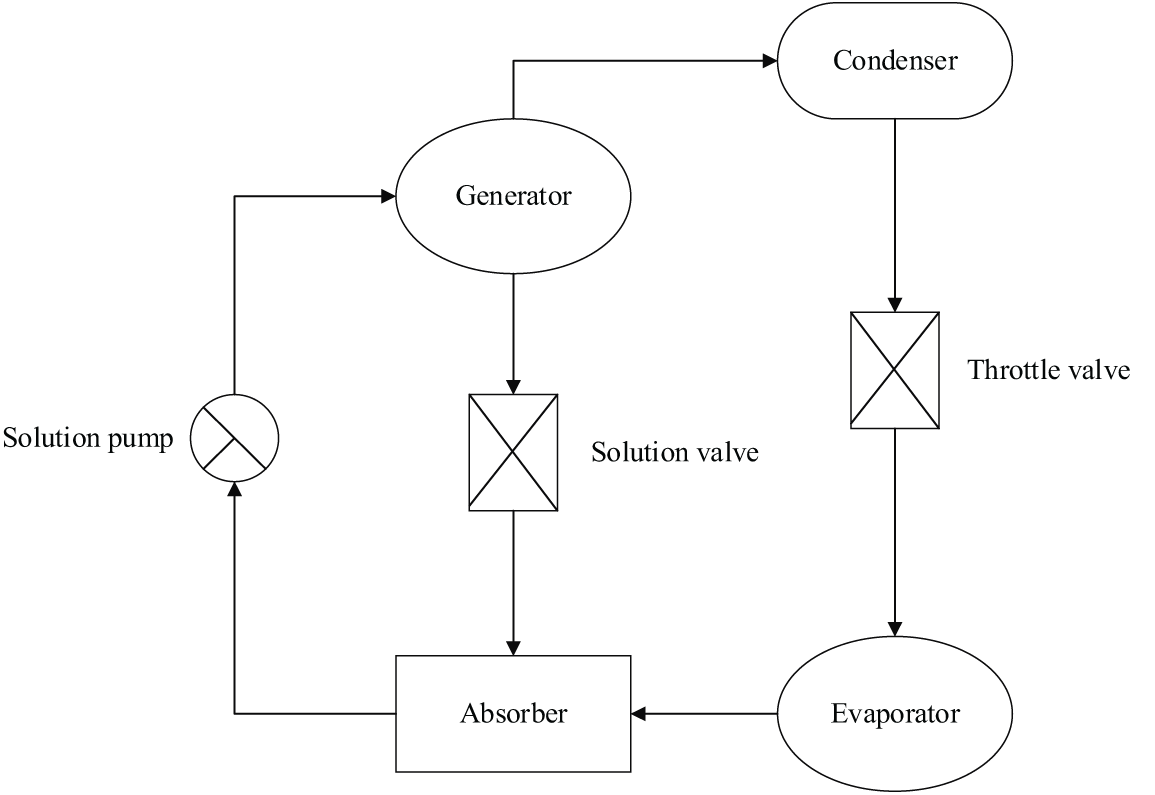
Figure 1: The absorption refrigeration system
Fig. 1 illustrates that an absorption refrigeration system consists of four parts: the absorber, the generator, the condenser, and the evaporator.
The absorber is to absorb the falling film. The ion solution with a high concentration from the generator is diluted by the water vapor, and then the ion solution with a lower concentration re-enters the generator from the absorber.
The generator is to heat the low-concentration ionic solution and evaporate the water vapor, so that the concentration of the ionic solution rises.
The condenser mainly condenses the gas. When the water vapor evaporates from the generator and enters the condenser, the cooler water condenses the steam into liquid water, and the water temperature in the condenser increases.
The evaporator receives the low-temperature liquid water and water vapor from the condenser, heats the liquid water, and then transmits the water vapor to the absorber.
Generally, the falling film flows on the surface of a vertical tube. The heat exchanger is used for heat exchange between the absorber and the generator, that is, the ionic solution with a high temperature and high concentration out of the generator exchanges heat with the ionic solution with a low temperature and a low concentration out of the absorber. Such a setting can reduce the temperature of the ionic solution with a high concentration, while expanding its absorption capacity.
It is a must to check the gas tightness of the system before the experiment. The device used in the experiment is under negative pressure, if the outside gas enters the device, a gas film will form between the falling liquid film and the water vapor to hinder the experiment, thus reducing the absorption effect. In the study, the bubble method is adopted for gas tightness test. Specifically, when the device is under positive pressure, the soap bubble test is carried out at each interface. If bubbles appear continuously, it proves that the outlet is leaking. After the inspection, the device is vacuumed and the absolute pressure is reduced to about 0 kPa. If the device is able to maintain such a steady pressure for 24 h, it indicates good gas tightness of the device.
2.2 Fluent Simulation of the Absorption Refrigeration System
Fluent software can simulate complex flows. Fluent software contains a variety of solvers based on density and pressure, as well as a particularly large number of engineered validated physical models. Its various solving techniques and multi-grid techniques endow it with a relatively fast convergence speed and high precision. Fluent software supports deformed mesh, hyper-mesh, sliding mesh, and mesh with discontinuous interface, etc., and involves three algorithms: coupled implicit algorithm, coupled explicit algorithm, and uncoupled implicit algorithm. Its many advanced turbulence models enable users to simulate turbulence, laminar flow, and non-viscous flow more accurately. In general, Fluent software has a wide range of applications, and it is efficient and time-saving, with high precision and good stability.
To explore the falling film flow of the ionic liquid on the vertical tube wall and investigate its influence on the absorption performance of the refrigeration system, the Fluent is used to simulate the different working conditions to analyze the characteristics of the liquid film. As mentioned before, the high-concentration [EMIM] [DMP] solution enters the absorber from the liquid-phase port, and attaches to the wall of the vertical tube. Then, it flows downwards due to the gravity. The high-temperature water vapor enters the absorber from the gas-phase port and interacts with the ionic solution, thereby affecting the falling film flow.
Because the flow rate in the absorber is not fast, which meets the laminar flow conditions, the falling film flow is assumed as laminar flow for numerical calculation. Generally, the VOF method is used for the numerical calculation of falling film flow, which can simulate the flow of two or more immiscible fluids based on the momentum equation, and can obtain the volume fraction of each part of the fluid [12]. Specifically, for a control body consisted of objects of different phases, the overall volume fraction is 1. If the volume fraction of a certain phase is known, the corresponding interface can be solved to understand the phase change. The phases that make up the unit are known based on the volume fraction of the unit grid.
If there is only a-th phase fluid in the cell grid, the volume fraction λa is 1, and if there is no a-th phase fluid, the volume fraction λa is 0. If there are other phases of fluid besides the third phase, the volume fraction λa is between 0 and 1. The VOF method can solve the problem of falling film flow.
The mass transfer equation is expressed as follows:
where ρ represents the unit density of the mixed-phase grid, calculated as follows:
The momentum equation is shown in Eq. (3).
where v is the flow velocity, τ is the viscosity of the mixed-phase grid, and a is the a-th phase fluid. F represents the set boundary conditions of the inlet, outlet and wall surface of the gas-liquid falling film flow. In the gas-liquid two-phase fluid flow, the gas phase is generally regarded as the main phase, and the liquid phase is the second phase. In a grid, the volume fraction of the two phases add up to 1. The boundary conditions need to be set in Fluent simulation calculation. The gas-liquid two-phase falling film flow needs to set the boundary conditions of the inlet, outlet, and wall surface. The liquid phase inlet of the falling liquid film should be set using speed inlet conditions, as shown in Eq. (5), which can be obtained according to the Reynolds number of the liquid film.
In Eq. (5), the inlet width of the liquid phase is expressed by ωm. It is perpendicular to the border of the inlet and inward. The pressure inlet conditions are applied to the gas phase inlet, which is on the top and right side, respectively. The distance between each vertical tube in the absorber is much larger than the calculation area, and it is more scientific to select the inlet of the gas phase as the right side. The smooth wall is adopted for wall boundary condition, that is, the boundary condition without slip. Initially, the calculation area will be filled with gas, so the initial liquid phase volume fraction is 0, the gas phase volume fraction is 1, and the velocities of the two phases at the inlet of the liquid phase are all zero.
After the calculation area is determined, it is needed to divide the area into grids, and each grid will store the corresponding calculation information [13]. According to the topological relationship, the grid can be divided into two types: structured grid and unstructured grid. Structured grid means that all internal nodes in the grid area have an equal number of adjacent elements, mainly quadrilateral (two-dimensional) and hexahedral (three-dimensional) elements. The structured grid is characterized by fast generation speed, good generation quality, and simple data structure, and it is suitable for calculation of fluid mechanics or surface stress concentration [14]. To generate structured grids, the fork tree method is mainly used. The generated data has good adaptability and high efficiency. Additionally, it has a good data structure, so it is very suitable for finite element grid local repartitioning. It is generated by adding a series of points or lines to divide a complete quadrilateral grid into 9 quadrilateral grids, and the data structure of the old unit is inherited. For a quadrilateral mesh, after each refinement, the 4 vertices in the original quadrilateral mesh will be retained. Two triangulation points on each side of the mesh connect with to those on the opposite side to generate 9 new quadrilateral meshes [15]. The structured grids are used to obtain more accurate results. The grid is divided by the same distance on the ordinate but it is dense. In the direction of the abscissa axis, that is, the direction of the falling film, the uniform division method is used to divide the grid.
The Fluent6.3.26 software is adopted for two-dimensional double precision. The PISO algorithm is used to couple pressure and speed, and the convection term is described in the second-order upwind style during discretion. The time term is given in the implicit discretization format, and the pressure term is performed with the PRESTO! algorithm. The VOF equation is calculated using Geo-Reconstruct numerical algorithm, and a time step is set to 1e–4s.
The thickness of the liquid film is calculated, and the average thickness of the falling film is calculated using Nusselt theory. In addition, the thickness of the liquid film under different Re values is calculated and compared with theoretical data. The comparison results reveal that the two have a high degree of agreement, which verifies the correctness of this model.
2.3 Performance Analysis of the Absorption Refrigeration System
In order to analyze the performance of the absorption refrigeration system, it is necessary to understand the energy conversion in the system. The schematic diagram of the energy exchange is shown in Fig. 2.
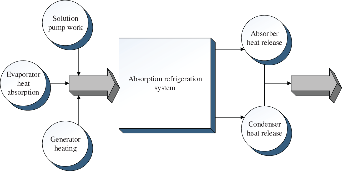
Figure 2: Schematic diagram of energy conversion of absorption refrigeration system
It is evident from Fig. 2 that the refrigeration system exchanges the energy with outside world through the generator, absorber, solution pump, condenser, and evaporator. According to the law of conservation of energy in thermodynamics, Eq. (5) is obtained.
In Eq. (6), the heat entering the system is on the left side of the equation. The increased heat in the generator is represented by Qf. The heat released in the absorber is represented by Qx. The work of the solution pump when the system is running is represented by Wr. The heat released by the condenser is represented by Ql. The heat absorbed by the evaporator is represented by Qz. In the energy system of the refrigeration system, the work done by the solution pump is negligible compared to the heat added to the generator, and the heat absorbed by the evaporator is not an effective heat consumption. Therefore, the calculation method of the coefficient of heat supply of the absorption refrigeration system is shown in Eq. (6).
In which, the coefficient of heat supply is represented by δ.
It is assumed that the absorption refrigeration system cycle is reversible, the temperatures of the four parts are also equal. According to the second law of thermodynamics, the total entropy outside the refrigeration system becomes zero, as shown in Eqs. (7) or (8).
In Eqs. (8) and (9), Tf and ΔSf are the temperature and entropy changes of the generator; Tz and ΔSz are the temperature and entropy change of the evaporator; Tx and ΔSx represent the temperature and entropy change of the condenser; and Tl and ΔSl represent the temperature and entropy change of the absorber.
Based on Eq. (6), the coefficient of heat supply of the absorption refrigeration system can be obtained as shown in Eq. (9).
In Eq. (9), the temperature of the heated medium is represented by Te. The thermal efficiency of the Carnot cycle is represented by η. The coefficient of refrigeration of the reverse cycle of the Carnot cycle is expressed by COP. The correctness and rationality of the experimental design and method adopted in this study have been checked and approved, which can ensure the accuracy of the research data and the integrity of information.
3.1 Comparison Results of the Liquid Film
The Fluent is used to simulate the falling film flow. The falling film characteristics of the [EMIM] [DMP] ionic liquid and the potassium bromide solution are compared, and the results prove that [EMIM] [DMP] ionic liquid is better.
Related physical parameters and operative conditions are given in Tabs. 1 and 2, respectively.
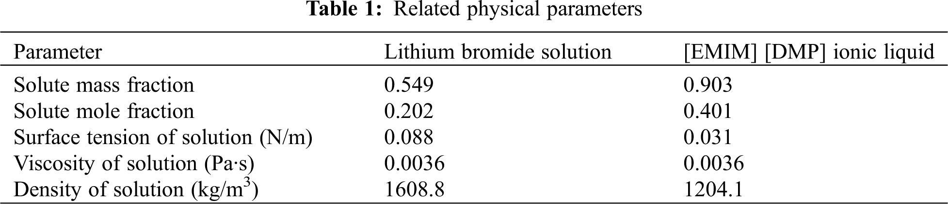
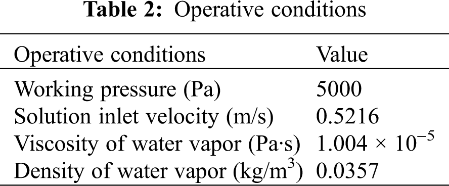
Fig. 3 shows the wave character of liquid film of the two solutions.
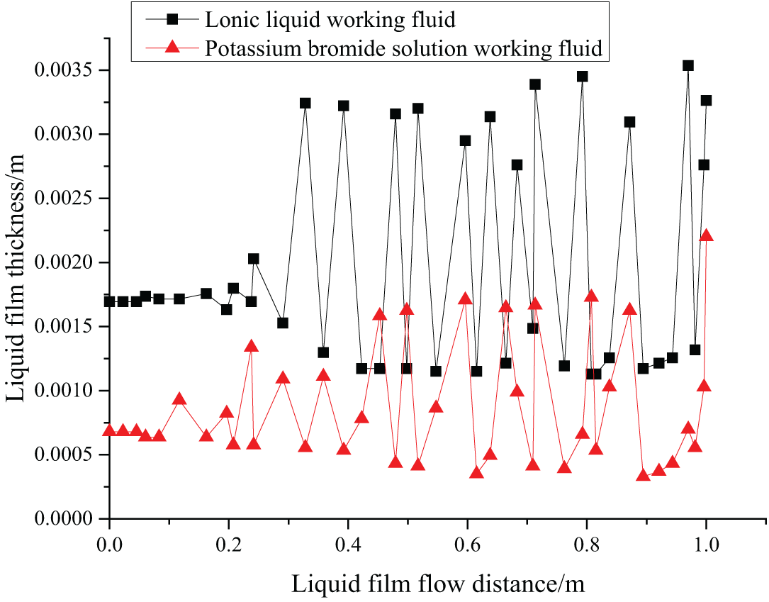
Figure 3: The wave character of the liquid film
The falling film flow of the two fluids is obtained by Fluent simulation, and the wave character diagram is drawn involving the thickness of the liquid film and the flow distance of the liquid film. According to Fig. 3, the thickness of the liquid film does not change with the flow distance, which proves that the falling film flow is stable. When the gas phase gradually interacts with the liquid fluid, the falling film flow has a large fluctuation. There are inertial and capillary waveforms. The inertial wave has relatively low vibration frequency but large amplitude. The capillary wave has a relatively high vibration frequency but small amplitude. Generally, capillary waves appear firstly and then transform into inertial waves. The large amplitude inertial wave vibration enables a large contact area with the gas, and the absorption effect is better.
Fig. 3 indicates that the potassium bromide working fluid converts capillary waves into inertial waves when the flow distance reaches 0.1 m, while [EMIM] [DMP] ionic liquid converts capillary waves into inertial waves only when the flow distance reaches 0.2 m. Compared with potassium bromide working fluid, the inertial wave generated by [EMIM] [DMP] ionic liquids has larger amplitude and longer wavelength, arising from different surface tensions. The interaction between the gas and the liquid phase causes the liquid film of the ionic liquid to generate an inertial wave with larger amplitude, producing better absorption effects.
When the falling film flow is in a stable state, the WSS between [EMIM] [DMP] ionic liquid working fluid and potassium bromide solution to the vertical pipe wall is given as Fig. 4.
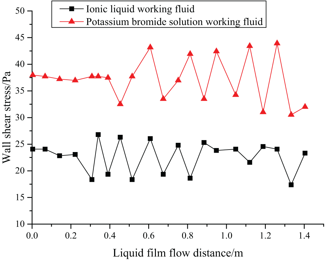
Figure 4: Changes of WSS with the flow distance
Studying the WSS between the liquid film and vertical tube helps to understand the velocity boundary layer state, and it can also further reflect the fluid flow conditions. According to Fig. 4, when the falling film flow of the two fluids is stable, the WSS of the two fluids is relatively stable, but the WSS changes with the thickness of the liquid film, and there is a specific periodicity. The [EMIM] [DMP] ionic liquid has smaller amplitude, longer duration of capillary wave, and thicker liquid film, and thus it has a bigger WSS.
3.2 The Effect of Ionic Liquids on the Performance of Absorption Refrigeration System
The COP and the coefficient of heat supply are calculated to analyze the effect of [EMIM] [DMP] + H2O on the performance of the absorption refrigeration system. As mentioned above, the COP and coefficient of heat supply of the refrigeration system can be affected by the temperature of the generator and the temperature of the heat transfer medium. Therefore, the COP and coefficient of heat supply of [EMIM] [DMP] + H2O ionic liquid refrigeration system are tested under different generator temperatures and circulating water temperatures.
When the generator temperature is 100°C and the circulating water temperature is 25°C, the COP and coefficient of heat supply of the absorption refrigeration system are shown in Fig. 5.
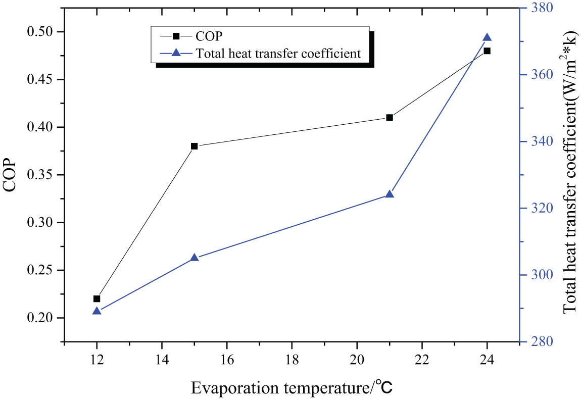
Figure 5: The COP and coefficient of heat supply with 100°C generator temperature and 25°C circulating water temperature
When the generator temperature is 80°C and the circulating water temperature is 25°C, the COP and coefficient of heat supply of the absorption refrigeration system are shown in Fig. 6.
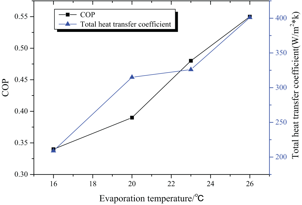
Figure 6: The COP and coefficient of heat supply with 80°C generator temperature and 25°C circulating water temperature
When the generator temperature is 100°C and the circulating water temperature is 30°C, the COP and coefficient of heat supply of the absorption refrigeration system are shown in Fig. 7.
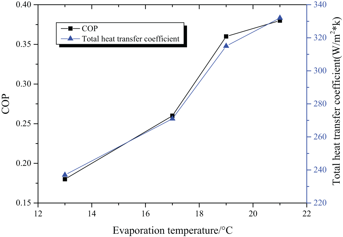
Figure 7: The COP and coefficient of heat supply with 100°C generator temperature and 30°C circulating water temperature
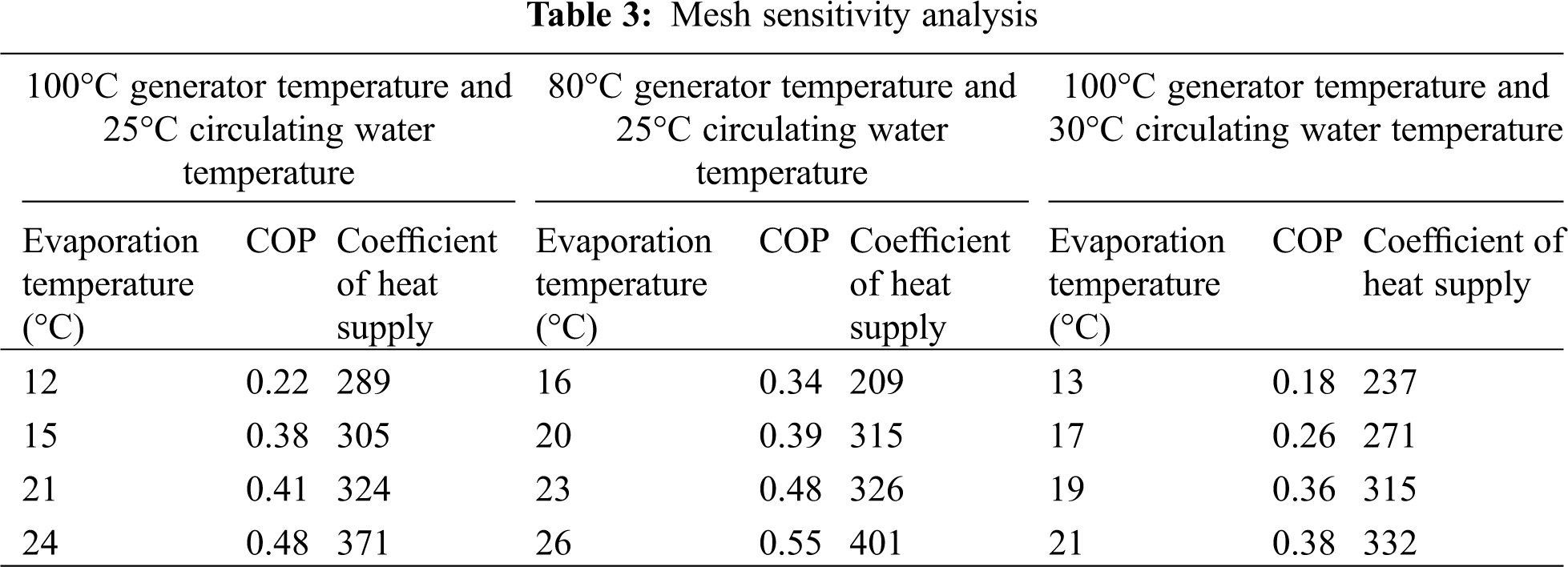
At different generator temperatures and circulating water temperatures, the variation of the COP and heating coefficient of the absorption refrigeration system with the evaporation temperature is shown in Tab. 3.
According to the COP and coefficient of heat supply of the refrigeration system under different operating conditions, it can be deduced that both these two indicators increase with the elevation of the evaporation temperature. Figs. 5 and 6 indicate that a lower generator temperature leads to a bigger COP and a bigger coefficient of heat supply. According to Figs. 5 and 7, it is deduced that the COP and coefficient of heat supply increase with the decrease of the circulating water temperature, with the best COP being 0.55. Therefore, [EMIM] [DMP] + H2O ionic liquid is suggested in the absorption refrigeration system, but setting the temperature of each part of the system should be managed to realize refrigeration effects.
Fig. 8 shows the system simulation results and the test results in the reference. It is noted that, in general, the simulation results are superior to the test results in the reference. Specifically, the condenser differs by 5.78%, and the evaporator and the heat exchanger have the highest coincidence, and only the simulation result of the evaporator is lower than the reference value. Hence, the ionic liquid working fluid-based absorption refrigeration system is worthy of promotion.
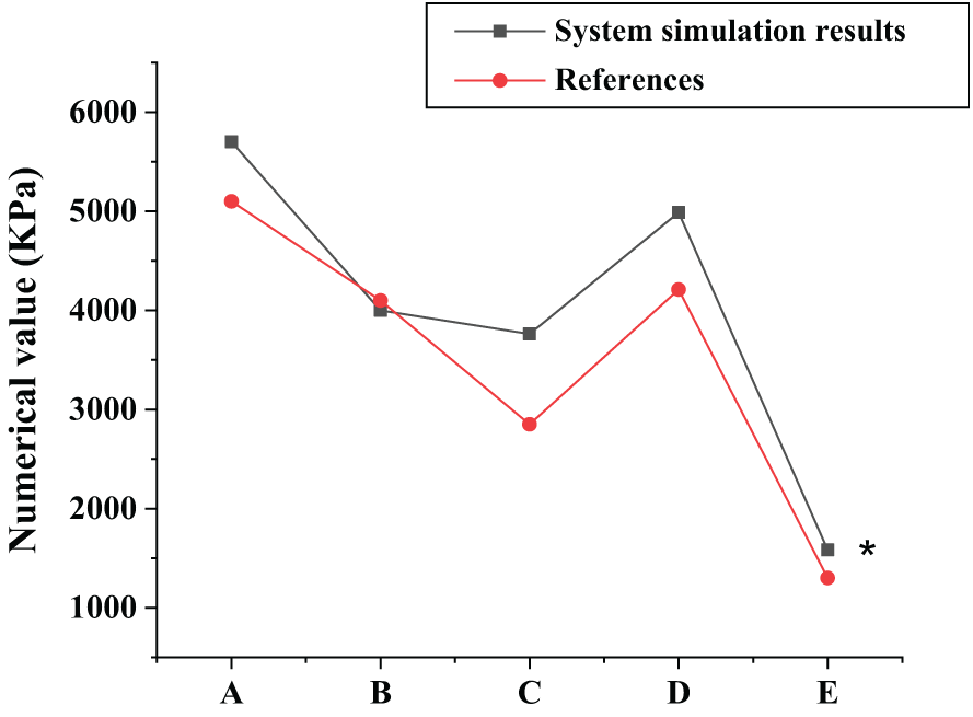
Figure 8: The system simulation results. A: the generator; B: the evaporator; C: the condenser; D: the absorber; E: the heat exchanger
To investigate the effect of ionic liquid working substances on the refrigeration system, the falling film flow of the [EMIM] [DMP] + H2O ionic liquid is stimulated using the Fluent. Then, the wave character of its liquid film and WSS are analyzed and compared with those of potassium bromide solution. The study provides reference for the simulation of ionic liquid flow by Fluent. However, some limitations should be noted. The [EMIM]] [DMP] + H2O ionic liquid proposed in this study is not widely used in practice, and it should be compared with other working substances in a comprehensive manner. Research in this direction can be carried out in the future to strengthen the findings of the study.
Acknowledgement: I gratefully acknowledge the guide of my teacher.
Funding Statement: The authors received no specific funding for this study.
Conflicts of Interest: The authors declare that they have no conflicts of interest to report regarding the present study.
1. Minea, A. A., Murshed, S. M. S. (2018). A review on development of ionic liquid based nanofluids and their heat transfer behavior. Renewable and Sustainable Energy Reviews, 91, 584–599. [Google Scholar]
2. Sözen, A., Gürü, M., Khanlari, A. (2019). Experimental and numerical study on enhancement of heat transfer characteristics of a heat pipe utilizing aqueous clinoptilolite nanofluid. Applied Thermal Engineering, 160, 114001. [Google Scholar]
3. Hari, B., Brouwer, J. P., Dhir, A. (2019). A computational fluid dynamics and finite element analysis design of a microtubular solid oxide fuel cell stack for fixed wing mini unmanned aerial vehicles. International Journal of Hydrogen Energy, 44(16), 8519–8532. [Google Scholar]
4. Chen, S., Peng, X., Bao, N. (2019). A comprehensive analysis and optimization process for an integrated liquid cooling plate for a prismatic lithium-ion battery module. Applied Thermal Engineering, 156, 324–339. [Google Scholar]
5. Akrami, M., Javadi, A. A., Hassanein, M. J. (2020). Study of the effects of vent configuration on mono-span greenhouse ventilation using computational fluid dynamics. Sustainability, 12(3), 986. [Google Scholar]
6. Lv, Z., Xiu, W. (2020). Interaction of edge-cloud computing based on SDN and NFV for next generation IoT. IEEE Internet of Things Journal, 7(7), 5706–5712. [Google Scholar]
7. Wang, X., Xie, Y., Day, R. (2018). Performance analysis of a novel thermal management system with composite phase change material for a lithium-ion battery pack. Energy, 156, 154–168. [Google Scholar]
8. Thakur, P., Sonawane, S. S. (2019). Application of nanofluids in CO2 capture and extraction from waste water. Journal of Indian Association for Environmental Management, 39(1–4), 4–8. [Google Scholar]
9. Yu, Q., Romagnoli, A., Yang, R. (2019). Numerical study on energy and exergy performances of a microencapsulated phase change material slurry based photovoltaic/thermal module. Energy Conversion and Management, 183, 708–720. DOI 10.1016/j.enconman.2019.01.029. [Google Scholar] [CrossRef]
10. Dai, J., Mou, J., Liu, T. (2020). Influence of tip clearance on unsteady flow in automobile engine pump. Fluid Dynamics & Materials Processing, 16(2), 161–179. DOI 10.32604/fdmp.2020.06613. [Google Scholar] [CrossRef]
11. Liebschner, R., Gerlach, G. (2018). 3D-FEM simulation of a MEMS-based electrocaloric Ba (Zr0. 2Ti0. 8) O3 thin-film microfluidic refrigeration device. Energy Technology, 6(8), 1553–1559. DOI 10.1002/ente.201800257. [Google Scholar] [CrossRef]
12. Ansari, M. I., Anwer, S. F. (2018). Numerical analysis of an insect wing in gliding flight: Effect of corrugation on suction side. Fluid Dynamics & Materials Processing, 14(4), 259–279. DOI 10.32604/fdmp.2018.03891. [Google Scholar] [CrossRef]
13. Song, L., Zhang, H., Yang, C. (2019). Thermal analysis of conjugated cooling configurations using phase change material and liquid cooling techniques for a battery module. International Journal of Heat and Mass Transfer, 133(23), 827–841. DOI 10.1016/j.ijheatmasstransfer.2018.12.157. [Google Scholar] [CrossRef]
14. Kumar, K. G., Manjunatha, S., Gireesha, B. J. (2020). Melting heat transfer of prandtl fluid over a stretching surface in the presence of fluid particles suspension. Fluid Dynamics & Materials Processing, 16(2), 131–146. DOI 10.32604/fdmp.2020.0152. [Google Scholar] [CrossRef]
15. Ghaderian, J., Sidik, N. A. C., Kasaeian, A. (2017). Performance of copper oxide/distilled water nanofluid in evacuated tube solar collector (ETSC) water heater with internal coil under thermosyphon system circulations. Applied Thermal Engineering, 121, 520–536. DOI 10.1016/j.applthermaleng.2017.04.117. [Google Scholar] [CrossRef]
 | This work is licensed under a Creative Commons Attribution 4.0 International License, which permits unrestricted use, distribution, and reproduction in any medium, provided the original work is properly cited. |