| Fluid Dynamics & Materials Processing |
DOI: 10.32604/fdmp.2022.016640
ARTICLE
Experimental Study on Heavy Oil Drag Reduction in Horizontal Pipelines by Water Annular Conveying
1State Key Laboratory of Oil and Gas Reservoir Geology and Exploitation, Southwest Petroleum University, Chengdu, 610500, China
2China Petroleum Engineering & Construction Corp North Company, Renqiu, 062552, China
3China National Petroleum Corporation, Beijing, 100000, China
4Institute of Mechanics, Chinese Academy of Science, Beijing, 100190, China
*Corresponding Authors: Jiaqiang Jing. Email: jjq@swpu.edu.cn; Shiying Shi. Email: shishiying@imech.ac.cn
Received: 08 April 2021; Accepted: 12 August 2021
Abstract: Transportation of heavy oil by the so-called water-ring technique is a very promising method by which pressure drop and pollution can be significantly reduced. Dedicated experiments have been carried out by changing the phase’s density, viscosity, velocity and interfacial tension to systematically analyze the characteristics of the water ring. On the basis of such experimental data, a mathematical model for pressure drop prediction has been introduced. This research shows that as long as the density of oil and water remains the same, a concentric water ring can effectively be formed. In such conditions, the oil-water viscosity difference has little effect on the shape of water ring, and it only affects the pressure drop. The greater the viscosity of heavy oil, the smaller the pressure drop of the oil-water ring transportation system. The influence of phases’ interfacial tension on the characteristics and pressure drop of the heavy oil-water ring can be considered negligible. The pressure drop prediction model introduced on the basis of the Buckingham’s principle provides values in good agreement (95%) with the experimental data.
Keywords: Heavy oil; oil-water ring; boundary layer; experiment; pressure drop model
Heavy oil is a non-conventional oil resource with the largest known reserves in the world. Due to its high viscosity that limits its application, various drag reduction technologies have been researched and utilized to improve heavy oil’s fluidity. In recent years, with oil discovery happening in offshore and alpine areas, oilfield development has focused on the drilling and production of heavy oil in these areas. Heavy oil is also predicted to become the future of world crude production [1].
However, heavy oil is much more difficult to transport than ordinary crude. Conventionally, heavy oil is heated or diluted to reduce its viscosity and drag. Advances in the past decades have seen viscosity reduction achieved via chemical modification and emulsification. Heavy oil is characteristically highly dense and viscous, contains less wax and has low condensation points with poor fluidity, leading to high development and operation costs. Therefore, it is important to explore new technologies for heavy oil production and transportation that are safe, economical and consume less energy [2].
Over the past 40 years, developing technology that reduces fluid’s viscosity at the boundary layer to achieve lower flow resistance has become a major research topic. Bensakhria et al. [3] concluded that under laboratory conditions, the use of water ring technology is able to lower heavy oil’s pipe pressure as much as 90%, with the stable oil-water ring achieving a drag reduction of 95%. Using the same technology, Glass et al. [4] further reported that the lowest pipe pressure occurred at water-oil ratio of 30%–40%. The requirements for the formation a stable oil-water ring was reviewed by Antonio et al. [5].
However, since the density of water is slightly higher than that of ordinary heavy oil, transportation of heavy oil using water ring technology poses certain challenges. One key issue is that at certain pressure and temperature, the denser water would sink and thus disrupts the concentric water ring. This would lead to adhesion between heavy oil and the upper wall of the pipe, which adversely affects the drag reduction. In order to overcome this stability issue, researchers mostly focused on three approaches to forming stable water rings: reduce the density difference between water and heavy oil, reduce the emulsification effect of water on heavy oil, and improve the hydrophilicity of the pipe wall. Ho et al. [6] prepared water-in-oil emulsion to increase the density of the central oil flow, and added anionic surfactant to reduce the oil-water emulsification, thus obtaining better stability.
Since the early 1980s, the feasibility of gathering and transporting highly viscous crude at low temperature on field were studied by various scholars [7–10]. After analyzing various issues on water ring transportation, Pan et al. concluded that stable annual flow can be obtained by the use of elastic aqueous solution and gel adsorption layer. Nevertheless, given the limitation of the experimental conditions, the flow characteristics of oil and water in the pipe cannot be observed, and the conditions affecting the water ring stability cannot be systematically studied. The pressure drop formula of the stable heavy oil-water ring transportation was not definitive and required an iterative solution.
We have previously established an experimental water ring transportation device for oil with viscosity exceeding 5,000 mPa·s. In this study, the factors affecting the oil-water two-phase flow pattern in horizontal pipes were systematically researched to obtain the flow pattern and pressure drop formula/relationship of oil-water under different transportation conditions. Based on the dimensional analysis of experimental data using Buckingham π theorem, a pressure drop math model on heavy oil-water ring was established, providing for rapid calculation with a wide range of application. These research results not only have significant academic value, but can also be used as a reference during the study on heavy oil transportation at low temperature.
2 Experimental Materials and Methods
High viscosity silicone oil and aqueous solution are used as experimental media, with the silicone oil dyed black for ease of observation. Previous studies suggested that the stability of water ring is mainly affected by the surface tension defined by the differences in density, viscosity and velocity between oil and water [11]. Therefore, eliminate the impact of these factors on the experimental results, we selected a range of materials for each parameter tested. For example, at 20°C, 5 kinds of silicone oil with the density of 950 kg/m3 and the viscosity of 5,000, 8,000, 11,000, 22,000, and 32,000 mPa·s were prepared to simulate heavy oil. The aqueous solution was prepared with pure water and absolute ethyl alcohol according to the density required. At 20°C, the viscosity of absolute ethyl alcohol is very close to that of water. In this way, the viscosity has little influence during preparation of aqueous solution of different densities.
The experimental device used for heavy oil-water ring transportation was established in our previous study [11] to study the drag reduction characteristics of water ring. The device consists of water tank, heavy oil tank, mixed oil tank, water pump, heavy oil pump, liquid ring generator, differential pressure transmitter, rotameter, and frequency converter (Fig. 1 for the device and Fig. 2 for the liquid ring generator). The test pipe in the test section was a transparent pipe with a diameter of 32 × 3 mm and a length of 1.0 m placed in the pressure monitoring section.
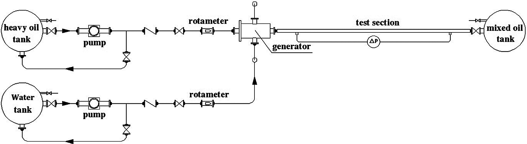
Figure 1: Schematic diagram of test system
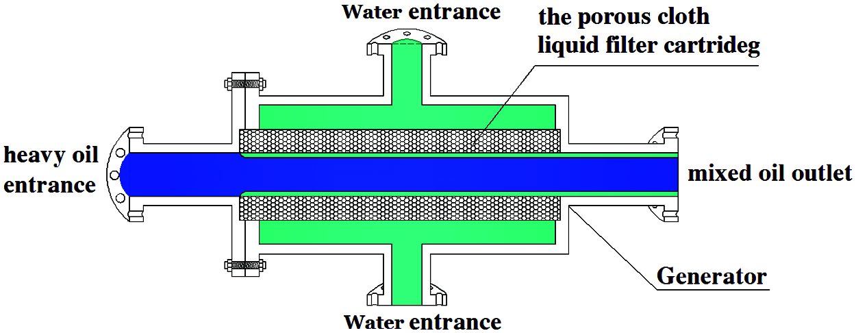
Figure 2: Structure diagram of water-ring generator (top view)
3 Factor Analysis of Water Ring Stability
3.1 Influence of Two-Phase Density Difference
The heavy oil with density of 950 kg/m3 and viscosity of 32,000 mPa·s was used to study the effect of oil-water density difference on the stable heavy oil-water ring transportation. The influence of density difference between the biphasic solution on the stability of water ring was analyzed by manipulating the density of the aqueous phase (940~990 kg/m3, increment gradient of 10 kg/m3). The apparent velocity of oil-water was maintained at 0.5 m/s. Fig. 3 gives the oil-water flow pattern in the pipe under different density differences.
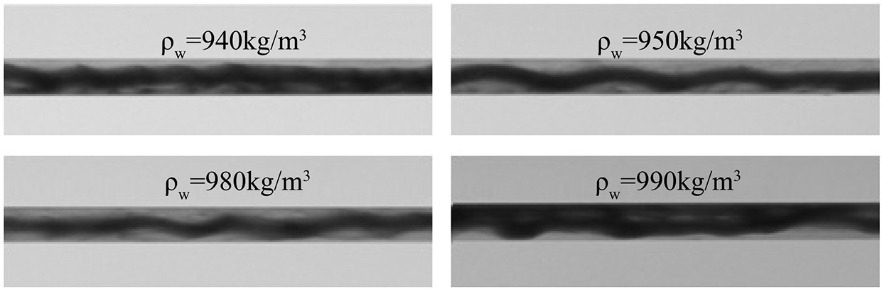
Figure 3: Oil-water flow pattern in pipe under different density differences
Fig. 3 shows that the heavy oil flows in a downward eccentric ring when the aqueous phase has the density lower than that of heavy oil. With the increase in the density of the aqueous phase, the heavy oil core gradually moves up to the center of the pipe, and presented a relatively stable water ring transportation. The fluctuations observed in the heavy oil core were due to the belt-driven gear pump used which has instantaneous changes in flow output. As the density of aqueous solution gradually increases, the heavy oil core continues to move up. When the density of the aqueous solution reached 990 kg/m3, the heavy oil displayed wall sticking property and the water ring loses stability. This indicates that the density difference between the oil and water phases is the sole reason for the formation of eccentric oil-water ring.
The curves of pressure drop gradient per unit pipe length of heavy oil-water ring transportation under different water phase densities were also recorded (Fig. 4). When analyzed in conjuncture with Fig. 3, it can be seen that increase in water density resulted in the rise in the pressure drop per unit pipe length, as the pressure drop per unit pipe length does not increase much prior to the occurrence of heavy oil wall-sticking phenomenon. This suggests that for relatively stable water ring, the pressure drop per unit pipe length is less affected by heavy oil at the core area.

Figure 4: Influence of water phase density on pressure drop per unit pipe length
3.2 Influence of Two-Phase Viscosity Difference
Four samples with the density of heavy oil and aqueous solution at 950 kg/m3, and with heavy oil viscosity of 5,000, 8,000, 22,000, and 32,000 mPa·s were selected to study the influence of oil-water phase viscosity difference on the stable heavy oil-water ring transportation which is shown in Fig. 5. The apparent velocity of oil and water phases were maintained at 0.5 m/s, and the oil-water flow pattern in the pipe under different viscosities were observed.
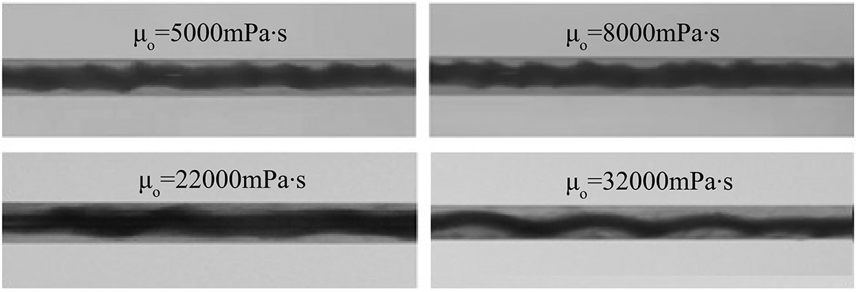
Figure 5: Oil-water flow pattern in pipe under different viscosities
Our data shows that when oil and water were of the equal density, the heavy oil water ring flowed stably under various oil-water densities. When the viscosity of heavy oil was relatively low, the interface between heavy oil and water in the core area flowed in the form of small jagged waves. As the heavy oil’s viscosity increased, this interface gradually became smooth and presented a large wave flow. Hence, it can be surmised that the greater the heavy oil’s viscosity, the bigger the interphase friction between the oil core and the water ring, and the smaller the shear effect of water on the interface between water and heavy oil.
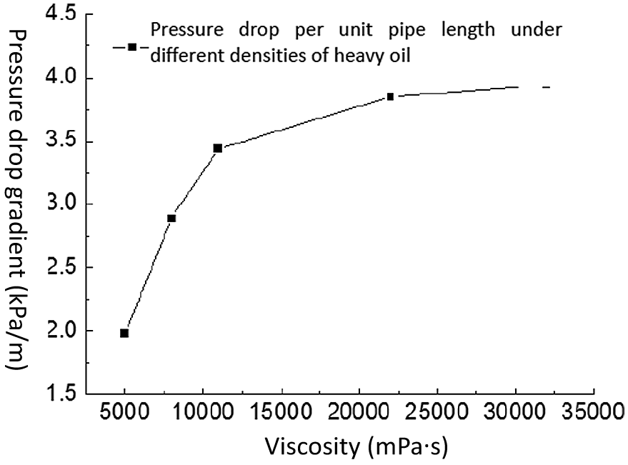
Figure 6: The effect of viscosity on curves of pressure drop gradient per unit pipe length
Fig. 6 gives the curves of pressure drop gradient per unit pipe length of heavy oil-water ring transportation at different viscosities. The curve showed that the pressure drop per unit pipe length increases with the increase of heavy oil viscosity. The heavy oil in the core area presented a continuous phase, and the interlayer friction increases with the increase of viscosity leading to increase in the overall pressure drop. However, the increment rate of pressure drop gradually decreases, indicating that the water ring can reduce the resistance of heavy oil transportation. The greater the viscosity of heavy oil, the better the drag reduction.
3.3 Influence of Two-Phase Velocity Difference
We further studied the influence of oil-water velocity difference on the heavy oil-water ring transportation using heavy oil with viscosity of 32,000 mPa·s with the density of heavy oil and aqueous solution at 950 kg/m3. By fixing the apparent velocity of oil phase at 0.5 m/s, the influence of water ring on the stability of heavy oil in the core area was analyzed by changing the apparent velocity of water phase.
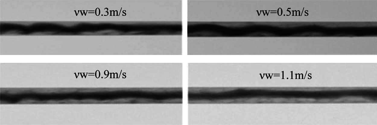
Figure 7: Oil-water flow pattern in pipe under different water velocities
Our results (Fig. 7) showed that with constant oil velocity, the fluctuation of heavy oil core gradually decreases with the increase of water velocity. The reason may be that with the increase of water velocity, the amount of heavy oil in unit time flowing through the pipe section decreases, and the shear on the oil-water interface increases during the flow process of water carrying high viscous oil. This would restrict the flow pattern of heavy oil in the core area and reduce its fluctuation. We further found that although proper increase of water velocity can improve the stability of heavy oil in the core area, the efficiency of heavy oil transportation was reduced. Therefore, an optimal transportation condition needs to be established in the actual design.
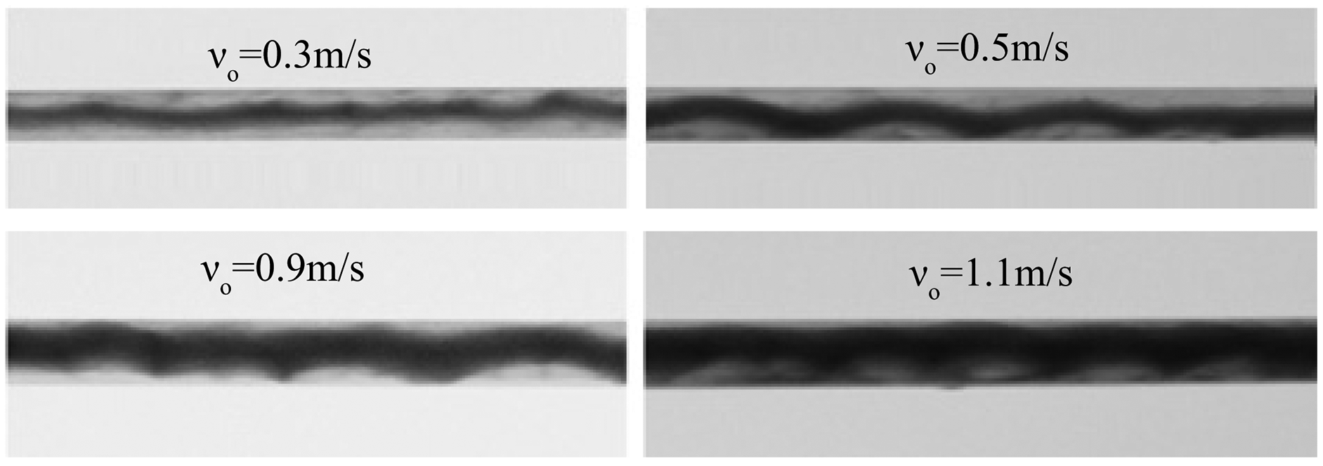
Figure 8: Oil-water flow pattern in pipe under different oil velocities
In contrast, when the water velocity remained unchanged at 0.5 m/s, the periodic fluctuation of heavy oil core gradually increases with the increase of the oil velocity (Fig. 8). This is mainly because with the increase of oil velocity, the rate of heavy oil flowing through the pipeline section increases due to the periodic injection of gear pump.
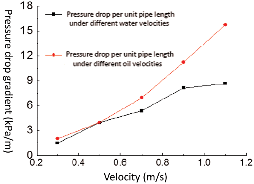
Figure 9: Curves of pressure drop gradient per unit pipe length at different velocities of water and oil
Our data further demonstrated that the pressure drop per unit pipe length increases no matter which phase velocity is increased (Fig. 9). When comparing the two curves, it can be observed that the pressure drop increased more with the increase of water velocity than with the increase of oil velocity. This is due to increase of heavy oil content in the pipe accompanying the increase of oil velocity, causing more internal friction when flowing with water as a result of its high viscosity.
3.4 Influence of Interfacial Tension Difference
The heavy oil with the density of both oil and water at 950 kg/m3, with their respective viscosity at 32,000, and 1.01 mPa·s was selected to study the influence of interfacial tension on the stability of heavy oil-water ring transportation. The oil-water apparent velocity was fixed at 0.5 m/s, and sodium dodecyl sulfate was added as a surfactant to the water to change the oil-water interfacial tension.

Figure 10: Oil-water flow pattern in pipe after adding different contents of sodium dodecyl sulfate
Our data (Fig. 10) showed that with the increase of surfactant in water, the oil-water interfacial tension decreases while the fluctuation frequency of heavy oil in the core area slightly increases.
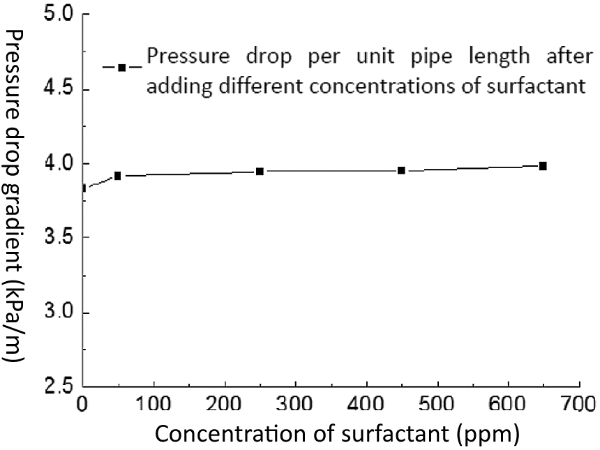
Figure 11: Curves of pressure drop gradient per unit pipe length after adding different concentrations of surfactant
An increase in surfactant concentration in water would slightly increase the pressure drop per unit pipe length (Fig. 11). Due to the decrease of oil-water interfacial tension, the fluctuation frequency of heavy oil would increase slightly, thus increasing the friction resistance. However, in general, changes in interfacial tension has insignificant effect on the pressure drop of heavy oil-water ring transportation.
4 Prediction of Pressure Drop of Stable Heavy Oil-Water Ring Transportation
Flow pattern is one of the most important factors affecting oil-water two-phase pressure drop [12]. At present, homogeneous and separated-flow models are the two relatively established pressure drop models for multi-phase fluid pipe transportation. Homogeneous model applies high velocity and mixture of oil and water, i.e., a two-phase flow [13] of water-in-oil or oil-in-water emulsion; Separated-flow model can be further divided into into two-layer, three-layer, and four-layer models [14–16]. These models apply to the flow of water and oil with interface in the pipe. The pipe pressure drop is then solved iteratively by establishing the fluid mechanics equation for each phase.
For annular flow, with one phase in the core area of the pipe and the other phase near the pipe wall, the pressure drop formula is reported less [17], let alone the non-iterative calculation model to quickly obtain more accurate results.
In the absence of relevant reference, dimensional analysis was used for modelling. Dimensional analysis is an important research method in natural science. It analyzes general rules followed by identifying quantitative relations between affairs according to the forms that all quantities must have. Through dimensional analysis, it can check whether the equations of physical phenomena are correct or not, and even provides clues to find physical phenomena and some laws [18].
From the relationship between dimensionless parameters, it can be seen that mixture density
According to the dimensional analysis theory, we selected
The data analysis shows that, with the increase of water density, Eu increases with the increase of
Since the underlying aim of this study is heavy oil-water ring transportation, and the amount of heavy oil transported in the practical application is known. Therefore, the modeling takes the heavy oil flow as the reference flow, and obtains the pressure drop solution by modifying the friction coefficient. Combined with the experimental data, it is found through calculation that the flowing Re of heavy oil occupying the central cross section is lower than 6.
The oil phase Reynolds number
The mixed magnetic Reynolds number
Therefore, the Stokes low Reynolds number flow pressure drop formula can be used to calculate:
The above formula is consistent with the experimental law, that is, the pressure drop increases with the increase of viscosity and with the increase of oil velocity.
Through a large number of data regression, the pressure drop prediction model for heavy oil-water ring transportation is shown as follows (when
where:

Figure 12: Comparison of model predicted pressure drop and tested pressure drop
We then compared the pressure drop results obtained from the experimental study with those predicted from our model (Fig. 12) and found good correlation between them, going as high as 95%. Our model is applicable to viscosity more than 10,000 mPa·s, and the error is less than 20%, making it suitable as a guide to production of heavy oil.
We systematically studied the effects of interphase density difference, viscosity difference, velocity difference, and interfacial tension on the oil-water flow in pipe using an experimental device for heavy oil-water ring transportation, and established a pressure drop predication model based on the experimental data obtained. Through this study, the following conclusions are drawn for oil viscosity higher than 5000 mPa·s:
1) Water ring transportation can greatly reduce the transportation resistance of heavy oil on the premise that heavy oil is confined to the central area of the pipeline (i.e., non-sticking to the wall).
2) Maintaining the same density of heavy oil and water is the only way to form a stable concentric water ring. When the other parameters are constant, the larger the viscosity of heavy oil, the better the drag reduction.
3) The differences between oil-water two-phase velocity does not impact the optimal velocity to achieve the minimum and stable pressure drop of heavy oil-water ring transportation. Therefore, in the specific application, it is necessary to establish the hydraulic-thermal transportation model through optimization to determine the transportation conditions.
4) The effect of oil-water interfacial tension on the stable transportation of heavy oil-water ring is small and negligible.
5) The pressure drop prediction model established by dimensional analysis method is suitable when the Reynolds number of heavy oil in the core area is less than 6. Under this working condition, the correlation between predicted and experimental data is as high as 95%. Engineering application requirements are met since the viscosity of heavy oil used is greater than 10000 mPa·s, and the error is less than 20%.
As China’s onshore heavy oil fields have entered more advanced stages of development, high water cut has become a common feature of old oilfields. For heavy oil transportation, the heavy oil-water ring transportation through proper facilities is necessary for reducing energy consumption of gathering and transportation systems. In addition, for super heavy oil, utilization of water ring as drag reduction fluid to realize low-temperature transportation is a new heavy oil transportation technology with great development prospects. However, further studies need to be done for heavy oil with Reo larger than 6.
Funding Statement: Foundation Projects: Major National R&D Project (2016ZX05025-004-005).
Conflicts of Interest: The authors declare that they have no conflicts of interest to report regarding the present study.
1. Homayuni, F., Hamidi, A. A., Vatani, A., Shaygani, A. A., Faraji Dana, R. (2011). Viscosity reduction of heavy and extra heavy crude oils by pulsed electric field. Petroleum Science and Technology, 29(19), 2052–2060. DOI 10.1080/10916461003699143. [Google Scholar] [CrossRef]
2. Acevedo, T., Alberto, E. (2017). Viscosity reduction of heavy crude oil through the addition of nanofluids on the non-thermal process. Escuela de Procesos y Energía. [Google Scholar]
3. Bensakhria, A., Peysson, Y., Antonini, G. (2006). Experimental study or the pipeline lubrication for heavy oil transport. Oil & Gas Science and Technology, 59, 523–533. [Google Scholar]
4. Glass, W. (1961). Water addition aids pumping viscous oils. Chemical Engineering Progress, 57, 116–119. [Google Scholar]
5. Antonio, C. (2001). Bann wart mode ling aspects of oil-water core-annular flows. Petroleum Science and Engineering, 32(2–4), 127–143. DOI 10.1016/S0920-4105(01)00155-3. [Google Scholar] [CrossRef]
6. Ho, W. S., Li, N. N. (1994). Core-annular flow of liquid membrane emulsion. AIChE Journal, 40(12), 1961–1968. DOI 10.1002/(ISSN)1547-5905. [Google Scholar] [CrossRef]
7. Bao, M. T., Fan, X. N., Cao, Q. F., Ma, A. Q., Guo, S. X. (2006). Progress in viscosity reducing technologies for recovery of viscous crude oils. Oilfield Chemistry, 23, 284–292. [Google Scholar]
8. Wu, B. F., Yang, Y. M., Shen, B. X., Lu, W. C. (2003). Synthesis and viscosity ruducing ability of SL series tercopolymers of long chain alkyl acrylate for extra-heavy crude oils. Oilfield Chemistry, 20(1), 78–82. DOI 10.1007/BF02974893. [Google Scholar] [CrossRef]
9. Taborda, E. A., Alvarado, V., Cortés, F. B. (2017). Effect of SiO2-based nanofluids in the reduction of naphtha consumption for heavy and extra-heavy oils transport: Economic impacts on the Colombian market. Energy Conversion & Management, 148, 30–42. DOI 10.1016/j.enconman.2017.05.055. [Google Scholar] [CrossRef]
10. Xin, Y. C., Liu, J. H., Xu, D. B., Hou, E. Q. (2007). Study on viscosity reduction of 4 heavy crude oils of venezuela through O/W emulsification. Oilfield Chemistry, 24(1), 24–29. DOI 10.1016/S1872-5813(07)60034-6. [Google Scholar] [CrossRef]
11. Jing, J. Q., Du, M. J., Yin, R. (2020). Numerical study on two-phase flow characteristics of heavy oil-water ring transport boundary layer. Journal of Petroleum Science and Engineering, 191(2), 107173. DOI 10.1016/j.petrol.2020.107173. [Google Scholar] [CrossRef]
12. Armando, M., Enrico, B., Alberto, D. L., Annibale, M. (2001). Process for moving heavy crude oils with water having a high content of salts. https://www.freepatentsonline.com/5934303.html. [Google Scholar]
13. Oglesby, K. D. (1979). An Experimental Study on the Effects of Oil Viscosity, Mixture Velocity and Water Fraction on Horizontal Oil-Water Flow (Master Thesis). University of Tulsa, USA. [Google Scholar]
14. Dehaghani, A., Badizad, M. H. (2016). Experimental study of Iranian heavy crude oil viscosity reduction by diluting with heptane, methanol, toluene, gas condensate and naphtha. Petroleum, 2(4), 415–424. DOI 10.1016/j.petlm.2016.08.012. [Google Scholar] [CrossRef]
15. Vedapuri, D., Bessette, D., Jepson, W. P. (1997). A segregated flow model to predict water layer thickness in oil-water flows in horizontal and slightly inclined pipes. Multiphase, 97(33), 75–105. [Google Scholar]
16. Trallero, J. L., Sarica, C., Brill, J. P. (1996). Oil-water flow patterns in horizontal pipes (Doctoral Dissertation). The University of Tulsa. [Google Scholar]
17. Du, S. L. (2018). Numerical simulation and experimental study on the process of heavy oil transportation by core annular flow (Master Thesis). China University of Petroleum Beijing. [Google Scholar]
18. Gao, M. C., Wu, J., Liu, X. C. (2018). Characteristics of air-water upward intermittent flows with surfactant additive in a pipeline-riser system. Journal of Hydrodynamics, 31(6), 287–295. DOI 10.1007/s42241-018-0034-5. [Google Scholar] [CrossRef]
 | This work is licensed under a Creative Commons Attribution 4.0 International License, which permits unrestricted use, distribution, and reproduction in any medium, provided the original work is properly cited. |