| Fluid Dynamics & Materials Processing |
DOI: 10.32604/fdmp.2022.017947
ARTICLE
Analysis of the Stability and Mechanical Characteristics of the Jointed Surrounding Rock and Lining Structure of a Deeply Buried Hydraulic Tunnel
1College of Water and Architectural Engineering, Shihezi University, Shihezi, 832000, China
2College of Water Resources and Hydropower, Sichuan University, Chengdu, 610065, China
*Corresponding Author: Haibo Jiang. Email: klaud_123@163.com
Received: 18 June 2021; Accepted: 11 September 2021
Abstract: On-site monitoring and numerical simulation have been combined to analyze the stability of the jointed surrounding rock and the stress inside the lining structure of a sample deeply buried hydraulic tunnel. We show that the deformation around the tunnel was mainly concentrated in the range 51.37 mm∼66.73 mm, the tunnel circumference was dominated by shear failure, and the maximum plastic zone was about 3.90 m. When the shotcrete treatment was performed immediately after the excavation, the deformation of the surrounding rock was reduced by 58.94%∼76.31%, and the extension of the plastic zone was relatively limited, thereby leading to improvements in terms of the stability of surrounding rock. When the support was provided at different time points, the stress of the surrounding rock in the shallow part of the tunnel was improved everywhere. In the tunnel section with high ground stress and joint development, when 10 cm steel fiber concrete spray layer and 40 cm C25 concrete secondary lining were used, the maximum tensile stress on the lining structure was 0.89 MPa, i.e., it was less than the tensile strength of concrete, which indicates that the internal force of the lining can meet the overall requirements.
Keywords: Diversion tunnel; high ground stress; lining; mechanical characteristics; numerical simulation
In recent years, deeply buried diversion tunnels have become more common, and the problem of high ground stress has become an urgent problem to be solved. In particular, the stability and safety of the lining structure under complex stress conditions after excavation and after support are in urgent need of in-depth study [1–3]. In the tunnel section with high ground stress and joint fractures, the geological disasters such as rock burst, large deformation, collapse, etc., are extremely likely to occur during the tunnel excavation process due to the influence of high ground stress. Plastic deformation will occur after excavation, and local collapse and plastic failure may occur in the initial support. Considering the complexity of engineering geology and the influence of high ground stress and joint fractures, the stability of the diversion tunnel is an issue that must be considered in the project.
Some scholars [4–11] used three-dimensional finite element software to analyze the mechanical characteristics of the cavern lining, the mechanism of lining cracking, the three-dimensional simulation of the cavern under high water pressure or shallow depth, the seepage flow of the submarine tunnel, the change of water pressure after the lining, and the mechanical characteristics of the secondary lining or the lining of large-diameter tunnels. The analytical formulas for the water consumption and water pressure of the subsea tunnel in the homogeneous surrounding rock were deduced, the lining cracking mechanism was analyzed, the basic factors affecting the lining cracking were investigated, and the changes of external load and internal force of the lining structure over time were summarized. Selahattin et al. [6] used three-dimensional finite element method to simulate the conventional tunnel excavation and lining, and the numerical results showed that the soil properties and excavation methods had an impact on the deformation of the excavation face and the settlement of the foundation. Peter et al. [7] studied the deformation of soft rock tunnel with high in-situ stress without lining through finite element software. Wang [12] studied the stress and structural optimization of the secondary lining of highway tunnels. The results showed that the vault, the waist of the arch, the corner of the secondary lining, the side wall of the inverted arch and the center of the inverted arch were the most unfavorable positions with the stress. Within a certain range, the safety of the secondary lining increased with the increase of the measured pressure coefficient. Gao et al. [13] analyzed the stress and deformation characteristics of the lining structure of Yuanliangshan Tunnel under the condition of high water pressure by using three-dimensional finite element numerical simulation. The study found that high water pressure had a significant impact on the lining structure of the tunnel, and the stress and deformation of the lining structure were large under the action of high water pressure, and the lining structure had a large longitudinal bending moment.
In summary, many scholars [14–16] have studied the mechanical characteristics of the lining under conditions such as high ground temperature tunnels, shallow burial or high water pressure. However, few scholars have focused on the stability of the surrounding rock of the hydraulic tunnel joints and the mechanical characteristics of the lining structure under the conditions of deeply buried tunnel with high ground stress and relatively developed joints and cracks. Finite element or finite difference in numerical simulation can only simulate a small number of large-scale joint faults. When considering a large number of joints, the numerical model of discrete element will become extremely difficult, and it cannot consider the anisotropic deformation and anisotropic failure caused by the joints and cracks. In this paper, discrete element software was used to perform numerical simulations. Due to its powerful pre-processing and discrete fracture network, discrete element software has great advantages in the simulation of jointed rock masses.
2 On-Site Monitoring and Stress Analysis of Hydraulic Tunnel Lining with High Ground Stress
According to engineering examples at home and abroad and literature [17], are the major factors result in the crack of the lining sidewall of high ground stress, the stress of surrounding rock, construction quality, etc., due to tunnel excavation energy concentrated, easy to cause the tunnel hole weeks after joint rock mass under high geostress, the savings in energy released within the surrounding rock, makes rock mass shear failure occurs, It leads to the increase of the loose circle around the diversion tunnel, and the sudden increase of the relaxation load after lining leads to the cracking and deformation of the initial support.
A deeply buried high ground stress hydraulic tunnel in Xinjiang is located in the Kezi Autonomous Prefecture, with a maximum buried depth of about 1700 m. The geology is complex. Due to the impact of high ground stress, a certain degree of rock burst may occur. The geological structure in the high ground stress section is mainly controlled by the development of joints and fractures. The faulted structures and stratigraphic joints along the cave line are relatively developed. The main occurrences are observed at 50°∼70°NW∠60°∼65°, 270°∼325°NE, and SW ∠75°∼85°. According to engineering geological data, the rock mass near the cavern is dominated by Type III surrounding rocks.
In order to understand the stress conditions around the tunnel and the lining structure, the stress characteristics of the surrounding rock support structure were further observed. By observing the stress of the surrounding rock support structure, it can provide a scientific basis for the construction and design of the high ground stress tunnel. Meanwhile, the stress characteristics in the field test can provide the model verification of subsequent numerical experiments and the comparison and verification of subsequent theories and numerical analysis results. In addition, it also accumulates relevant numerical experience for the expansion of the project. Through systematic analysis of the monitoring data, the characteristics and mechanism of the force change of the supporting structure can be obtained, which can provide reference for the design of the supporting structure, and finally determines the supporting scheme suitable for the excavation and operation period of the main tunnel.
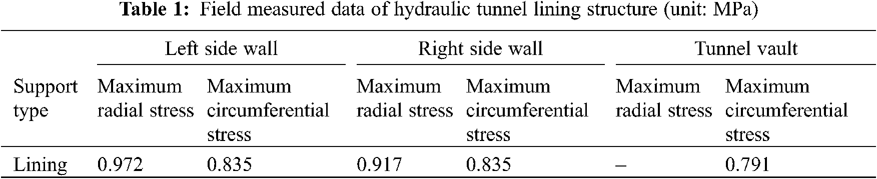
The high ground stress tunnel section is mainly concentrated between pile numbers 10 + 200 m∼15 + 642 m. The test tunnel was located at 110 m downstream of the 4# branch tunnel. This section had prominent high ground stress. The test tunnel was perpendicular to the excavated main tunnel and excavated towards the mountain. The test tunnel was a city gate cavern type, with a diameter of 4.6 m, a height of 5.3 m, and a length of 17 m. The first 5 m was the burrow section (the sprayed concrete treatment was actually carried out in the later period using the C25 concrete with the thickness of 50 cm). The last 12 m was the lining tunnel section, which was lined with ordinary lining consisting of 10 cm steel fiber concrete spray layer and 40 cm thick C25 concrete lining. The lining stress gauge was prefabricated inside the lining, mainly to test the internal stress behavior of the lining. The stress gauge was mainly used to monitor the stress of the lining structure. A total of 5 concrete stress gauges were arranged in the test tunnel section, located in the middle of the left and right walls, the left and right arches, and the vault positions. The stress gauge contained radial and circumferential directions. The radial stress mainly referred to the contact force between the surrounding rock and the lining, and the circumferential stress referred to the internal stress of the lining. The site layout is shown in Fig. 1.

Figure 1: Site layout
2.4 On-Site Monitoring Results and Force Analysis
The site investigation revealed that the cracks after excavation were mainly distributed near the vault and side walls. Due to the effect of high ground stress and joint cracks, the tensile stress value further increased after the excavation, opening and closing cracks appeared at the vault position, and cracks appeared in the wall. In order to avoid damage to the lining structure during the operation period, the excavated tunnel was secondly lined. After the lining, the stress observation instrument was installed to monitor the lining force. The lining stress gauge was prefabricated inside the lining to test the internal force of the lining. The radial and circumferential stresses in the lining of the sidewalls, arch waist and arch vault were monitored. The field monitoring data of the circumferential maximum stress and radial maximum stress for the side wall and vault of the hydraulic tunnel lining structure are shown in Table 1. The maximum circumferential stress and the radial stress appeared in left side wall. The maximum circumferential stress was 0.835 MPa, and the maximum radial stress was 0.972 MPa, which was much smaller than its tensile strength. Thus, the stability of the rock mass and lining structure around the tunnel in the lining section can be ensured.
3 Analysis of Mechanical Properties and Plastic Zone of Surrounding Rock Supporting Structure in High Ground Stress Area
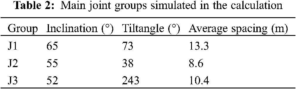
The model was established through discrete element software. Considering the boundary effect, the model size was 60 m × 60 m × 60 m. The section at the maximum buried depth of Type III surrounding rock was selected as a typical section for analysis. In the Mohr-Coulomb constitutive model, the MC yield criterion was used to analyze the stability of surrounding rock after excavation and support. The front, back, left, right, upper, and lower boundaries were all displacement constraints. The upper boundary was set as the self-weight stress boundary, and a vertical pressure of 45.9 MPa was applied. From the lateral pressure coefficient, 68.85 MPa was applied to the horizontal boundary. The stability of the surrounding rock in this section was mainly controlled by the development of joints. There were mainly three groups of joint groups, i.e., J1, J2 and J3, spreading over the entire model. The parameters of the three joint groups are shown in Table 2. The numerical calculation model is shown in Fig. 2.

Figure 2: Numerical model of tunnel jointed rock mass (a) three-dimensional diagram of ordinary lining (b) section view of ordinary lining (c) three-dimensional diagram of secondary support (d) section view of secondary support
Three models have been established in this paper. Model 1: no support measures are taken after excavation (for reference); Model 2: Shotcrete is carried out after excavation (simulation of the gross tunnel section in the field working conditions); Model 3: After excavation, ordinary support is carried out, that is, composed of 10 cm spray layer and 40 cm secondary lining (the lining section in the field working condition is simulated). Three-dimensional numerical simulation of extreme support time was carried out for model two and model three. The simulation of the gross tunnel section is to compare whether the supporting scheme proposed in this paper has better effect than the simple shotcrete. The comparison between Model 3 and the field monitoring data is to verify whether the simulation results are reasonable.
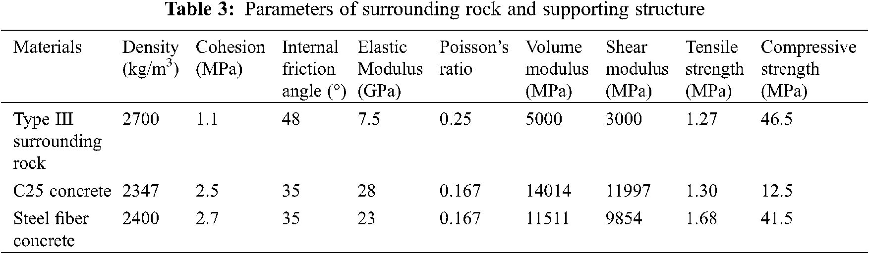
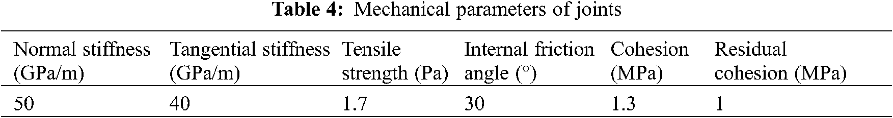
According to the values of mechanical parameters of the surrounding rock of similar projects and the actual engineering geological conditions, the relevant mechanical parameters were selected. The parameters of surrounding rock and supporting structure are shown in Table 3. The mechanical parameters of joints are shown in Table 4.
3.3 Simulation Results and Analysis
The maximum deformation of the displacement field after excavation was about 66.73 mm. After excavation, the maximum horizontal displacement appeared near the side wall, and the maximum value was about 66.23 mm. The maximum vertical displacement was near the arch bottom, and the maximum value was about 51.37 mm. When the ordinary lining was performed after the deformation was stabilized, compared with the excavation, the maximum deformation was reduced by 51.67%, the maximum horizontal displacement was reduced by 46.87%, and the maximum vertical displacement was reduced by 41.02%. When the ordinary lining was performed immediately after the excavation, compared with the deformation in the case of performing support after stabilized excavation, the maximum deformation was reduced by 58.94%, the maximum horizontal displacement was reduced by 62.74%, and the maximum vertical displacement was reduced by 76.31% is shown in Fig. 3. From the perspective of the displacement field, the immediate support after excavation was more conductive to the stability of the surrounding rock of the diversion tunnel.

Figure 3: Displacement cloud map of jointed rock mass near the diversion tunnel before and after support (unit: m) (a) displacement after excavation (b) displacement with support after deformation is stabilized (c) displacement with immediate support after excavation (d) horizontal displacement after excavation (e) horizontal displacement with support after deformation is stabilized (f) horizontal displacement with immediate support after excavation (g) vertical displacement after excavation (h) vertical displacement with support after the deformation is stabilized (i) vertical displacement with immediate support after excavation
The stress distribution cloud diagram is shown in Fig. 4. According to the law of stress change, the stress is redistributed after the excavation of the diversion tunnel due to the influence of high ground stress and the development of joints. After excavation, the stress was released in the area of 1 to 2.67 m around the tunnel, and the stress was 1.0 MPa around the tunnel. The left and right tensile stress was close to the tensile strength of the surrounding rock, which was not conducive to the stability of the rock mass. With the development of joint fractures, the surrounding rocks were very vulnerable to damage and cracks can be produced. Under the conditions of deep burial and high ground stress, stress concentration occurred near the side wall in the range of 3.45 to 5.51 m, and the maximum compressive stress was 53.69 MPa, which exceeded the compressive strength of the surrounding rock. It can be inferred that the high ground stress concentration caused rock mass instability around the tunnel. After excavation, ordinary lining was performed at different timings. After the support, the stress around the tunnel was improved, and the range of stress was smaller. There was no tensile stress around the diversion tunnel, and the surrounding rocks were compressed. The local maximum compressive stress was 43.52∼44.88 MPa, which was smaller than the compressive strength of the surrounding rock mass, thus the surrounding rock mass was in a stable state. The increase in stress in the shallow part of the tunnel with the support immediately after excavation was greater than that with the support after the stabilization of deformation. Therefore, compared to performing the support to the surrounding rock after the excavation was stabilized, the immediate support was more conducive to the stability of the surrounding rock.

Figure 4: Cloud map of stress distribution around the tunnel with and without support (unit: MPa) (a) maximum principal stress after excavation (b) maximum principal stress with support after the stabilization of deformation (c) maximum principal stress with immediate support after excavation (d) minimum principal stress after excavation (e) minimum principal stress with support after the stabilization of deformation (f) minimum principal stress with immediate support after excavation
The stress distribution of circular elastoplastic tunnels can be used to analyze the deformation and failure mechanism of deeply buried high ground stress diversion tunnels. Due to the development of high ground stress and joint fissures, with the excavation of the tunnel, the surrounding rock mass was easily damaged and had relatively poor stability. The plastic zone distribution of surrounding rock is shown in Fig. 5. The plastic zone was generated when the developed stress reached a certain value and satisfied a certain condition. The displacement increment and stress disturbance caused by the excavation caused the plastic yield zone around the excavation section to a large extent. The yield mode was shear yielding. Due to the development of joints, the plastic zone around the tunnel had a large distribution range and was mainly in shear failure. It can be seen from the figure that the shear failure on the arch waist, side walls, and arch bottom varies to different degrees. The plastic zone of the arch waist was about 1.31 m, and the maximum plastic zone was observed at the arch bottom, which was about 3.88 m. When the support was performed after the deformed surrounding rock was stabilized after excavation, the plastic zone was not expanded. When the support was carried out immediately after excavation, the scope of the plastic zone was limited around the diversion tunnel. Therefore, the immediate support after excavation was more conducive to the stability of surrounding rock.

Figure 5: Cloud map of the plastic zone of the diversion tunnel (a) plastic zone after excavation (b) plastic zone with support after deformation is stabilized (c) plastic zone with immediate support after excavation
3.3.4 Force Analysis of Lining Structure
By comparing the stress cloud maps of the lining structure with the support applied at two extreme times, we can conclude that only spray coating treatment should be performed after excavation, while the concrete structure is damaged due to excessive compressive stress. The simulation results of the tunnel showed that regardless of the timing of the support, although the stability of the jointed rock mass around the tunnel can be temporarily ensured to varying degrees, different types of damage would eventually occur to the lining structure. Therefore, the supporting effect of the lining section in this paper is particularly important. In order to provide a safety margin in the later stage, the lining tunnel section was simulated when the support was performed at the unfavorable supporting timing. After the secondary lining, the lining structure is shown in Fig. 6c. By comparing the lining structure of the lining tunnel section, the application of the secondary lining can not only ensure the stability of the jointed rock mass around the tunnel, but also lead to a smaller tensile stress generated on the supporting structure. The maximum tensile stress was only 0.89 MPa, which was smaller than the tensile strength of concrete. Therefore, the internal force of the lining can meet the overall requirements, which ensures the safety of the supporting structure during operation.

Figure 6: Stress cloud map of lining before and after support of hydraulic tunnel (unit: MPa) (a) lining structure when support is performed after the deformation is stabilized (b) lining structure with immediate support after the excavation (c) lining structure after the secondary support
No matter how the supporting time is, although the stability of the jointed rock mass around the tunnel can be guaranteed temporarily to different degrees, the lining structure will eventually suffer different types of damage. Therefore, the supporting effect of lining section is particularly important in this paper. Hole section of lining is simulated, adopt adverse supporting time, the purpose is to provide space for the security of its late, lining hole after secondary lining of segment lining structure as shown in Fig. 6c, through the hole and lining segment lining structure stress distribution were compared, to 10 cm shotcrete layer and 40 cm, secondary lining not only guarantee the stability of the joint rock hole week, The tensile stress generated on the supporting structure is also small, and the stress in the lining meets the requirements as a whole, so the safety of the supporting structure can be ensured during operation.
According to the on-site monitoring data, the maximum tensile stress generated by the lining structure was 0.90 MPa, which was slightly different from the maximum tensile stress from the simulation (0.89 MPa). Considering that the actual project may be affected by factors such as climate change and overly complex geological conditions, the actual geological environment cannot be restored 100% in the model. Thus, the error between the on-site monitoring data and the simulation results can be considered to be within the normal range, and the simulation results are relatively consistent with the on-site monitoring.
1) In deep high geostress, joint fissure development situation, through the hole section under different support time MAO’s displacement, stress, strain and plastic zone are analyzed, and the changes of supporting the more holes in the earlier weeks of joint rock mass stability, no matter under what kind of supporting time, cave surrounding rock stability can be guaranteed, but this may be a temporary stability, although the effect is different under different supporting time, the lining structure will be damaged even under the most favorable supporting time, so the long-term stability of the cavern cannot be guaranteed. The simulation results of the lining section showed that the maximum tensile stress generated by the lining structure was about 0.89 MPa, which was relatively consistent with the on-site monitoring results.
2) According to the analysis of the displacement field, the maximum deformation of the displacement field after excavation is 66.73 mm, the maximum horizontal displacement appears near the side wall with a value of 66.23 mm, and the maximum vertical displacement is at the vault with a value of 51.37 mm. In the simulation, the deformation and failure occurred mainly in the vault and the side wall, which was consistent with that in the field survey, the failure occurred near the vault and the side wall. Shotcrete support was carried out after the deformation was stabilized: the maximum deformation was reduced by 51.67%, the maximum horizontal displacement was reduced by 46.87%, and the maximum vertical displacement was reduced by 41.02%.
3) According to the analysis of stress field, there is about 1.0 MPa tensile stress around the tunnel after excavation. With the development of joints and fractures, the tunnel is easy to be damaged. The tunnel is a stress release zone, with the maximum stress of 33.25 MPa, and the stress concentration in local locations, the maximum compressive stress of 53.69 MPa, which exceeds the compressive strength of surrounding rock. After the secondary lining, the stress around the tunnel is improved, the tensile stress does not appear, and the tensile stress is transformed into compressive stress, and the local maximum compressive stress is 43.52 MPa, which is less than the compressive strength of the surrounding rock, which can ensure the stability of the surrounding rock after the lining.
4) From the analysis of the plastic zone, the displacement increment and stress disturbance caused by excavation cause the plastic yield zone around the excavation section to a large extent. After excavation, the plastic zone around the tunnel is distributed in a large range, the maximum is about 3.88 m, and the shear failure is the main part of the tunnel. Shotcrete treatment is carried out immediately after excavation, and the surrounding rock pressure is jointly borne by the surrounding rock and the lining, which will limit the range of rock plastic zone around the cave, and is beneficial to the stability of surrounding rock.
Acknowledgement: First and foremost, I would like to show my deepest gratitude to my supervisor, Dr. Shi Kebin, a respectable, responsible and resourceful scholar.
Funding Statement: This work was financially supported by the National Natural Science Foundation of China (Grant No. 51769031), Regional Innovation Guidance Plan Project of the XPCC (Grant No. 2021BB004).
Conflicts of Interest: The authors declare that they have no conflicts of interest to report regarding the present study.
1. Moritz, B. (2011). Yielding elements-requirements, overview and comparison. Geomechanics and Tunnelling, 4(3), 221–236. DOI 10.1002/geot.201100014. [Google Scholar] [CrossRef]
2. Barla, G., Bonini, M., Semeraro, M. (2011). Analysis of the behaviour of a yield-control support system in squeezing rock. Tunnelling & Underground Space Technology, 26(1), 146–154. DOI 10.1016/j.tust.2010.08.001. [Google Scholar] [CrossRef]
3. Li, C. C. (2012). Performance of D–bolts under static loading. Rock Mechanics and Rock Engineering, 45(2), 183–192. DOI 10.1007/s00603-011-0198-6. [Google Scholar] [CrossRef]
4. Galli, G., Grimaldi, A., Leonardi, A. (2004). Three-dimensional modelling of tunnel excavation and lining. Computers & Geotechnics, 31(3), 171–183. DOI 10.1016/j.compgeo.2004.02.003. [Google Scholar] [CrossRef]
5. Abdel-Meguid, M., Rowe, R. K., Lo, K. Y. (2003). Three-dimensional analysis of unlined tunnels in rock subjected to high horizontal stress. Canadian Geotechnical Journal, 40(6), 1208–1224. DOI 10.1139/t03-057. [Google Scholar] [CrossRef]
6. Selahattin, A., Murat, K., Abbas, T., Nguyen, G., Manchao, H. (2018). Effects of thermal damage on strain burst mechanism for brittle rocks under truetriaxial loading conditions. Rock Mechanics and Rock Engineering, 51(6), 1657–1682. DOI 10.1007/s00603-018-1415-3. [Google Scholar] [CrossRef]
7. Peter, P. K., Cai, M. (2012). Design of rock support system under rockburst condition. International Journal of Rock Mechanics and Mining Sciences, 4(3), 215–227. DOI 10.3724/SP.J.1235.2012.00215. [Google Scholar] [CrossRef]
8. Ortlepp, W. D., Stacey, T. R. (1994). Rockburst mechanisms in tunnels and shafts. Tunneling and Underground Space Technology, 9(1), 59–65. DOI 10.1016/0886-7798(94)90010-8. [Google Scholar] [CrossRef]
9. Li, F. M., Xiao, Y., Hua, X. M. (2018). Mechanism and treatment measures of secondary lining crack of pingtian shallow buried bias tunnel. Railway Engineering, 58(3), 43–45. DOI 10.3969/j.issn.1003-1995.2018.03.11. [Google Scholar] [CrossRef]
10. Xuan, M. H. (2016). Research on the thickness of shotcrete layer in the initial support of the shallow buried section of the yan kou mountain tunnel. Value Engineering, 32(27), 79–82. DOI 10.7666/d.y1955958. [Google Scholar] [CrossRef]
11. Luo, Y. (2011). Study on the mechanism of crack generation and control methods of tunnel lining. Southwest Jiaotong University Press. [Google Scholar]
12. Wang, C. H. (2012). Study on stress and optimization design of secondary linings in highway tunnel. Xi’an, China: Chang’an University. [Google Scholar]
13. Gao, X. Q., Qiu, W. G., Gao, Y. (2005). 3D numerical simulation of the lining structure under high water pressure in mountain tunnel. China Railway Science, China Railway Science Press. [Google Scholar]
14. Lai, H. P., Xie, Y. L., Liu, M., Xu, H. B. (2011). Mechanical characteristics for linings of shallow excavation metro tunnel in loess region. Chinese Journal of Geotechnical Engineering, 33(8), 1167–1172. DOI 10.1007/s12583-011-0163-z. [Google Scholar] [CrossRef]
15. Zhao, J., Wang, G. (2010). Unloading and reverse yielding of a finite cavity in a bounded cohesive-frictional medium. Computers and Geotechnics, 37, 239–245. DOI 10.1016/j.compgeo.2009.08.002. [Google Scholar] [CrossRef]
16. El Jiraria, S., Wonga, H., Deleruyelleb, F., Branquea, D., Berthozc, N. (2020). Analytical modelling of a tunnel accounting for elastoplastic unloading and reloading with reverse yielding and plastic flow. Computers and Geotechnics, 121, 1–12. DOI 10.1016/j.compgeo.2020.103441. [Google Scholar] [CrossRef]
17. Li, X. H., Li, D. X., Jin, X. G. (2005). Discussion on influence of initial support to stability and deformation of surrounding rock mass in soft rock tunnel. Chinese Journal of Rock and Soil Mechanics, 26(8), 1207–1210. DOI 10.1007/s11769-005-0030-x. [Google Scholar] [CrossRef]
 | This work is licensed under a Creative Commons Attribution 4.0 International License, which permits unrestricted use, distribution, and reproduction in any medium, provided the original work is properly cited. |