| Fluid Dynamics & Materials Processing |
DOI: 10.32604/fdmp.2022.017989
ARTICLE
A Study on the Relationship between Anodic Oxidation and the Thermal Load on the Aluminum Alloy Piston of a Gasoline Engine
School of Automotive Engineering, Guilin University of Aerospace Technology, Guilin, 541004, China
*Corresponding Author: Huali Guo. Email: guohuali@guat.edu.cn
Received: 21 June 2021; Accepted: 16 August 2021
Abstract: In order to analyze the influence of the anodizing process on the thermal load of an aluminum alloy piston, dedicated temperature tests have been carried out using the Hardness Plug method and the results for the anodized piston have been compared with those obtained separately for an original aluminum piston. In addition, numerical simulations have been conducted to analyze the temperature field and thermal stress distribution. Simulations and experiments show that the maximum temperature of the anodized piston is 16.36% and 5.4% smaller than that of the original piston under the condition of maximum torque and maximum power, respectively. The thermal stress of the temperature field of both pistons is within 50 Mpa, which meets the strength requirements of the material at high temperature. However, the area with significant thermal stress of the anodized piston is significantly smaller than that of the original piston. Combined with the fatigue analysis data, it can be seen that the safety factor of the anodized piston greater than 1.8 is 99.13%. Therefore, adopting the anodizing process not only reduces the piston thermal load, but also helps to extend its life and improve its reliability.
Keywords: Alloy piston; thermal load; anodic oxidation; hardness plug
The internal combustion engine is a machine which can convert thermal energy into mechanical energy [1], and the piston is the main heated part in the internal combustion engine. The thermal load is one of the factors that cause the piston to work abnormally, and the degree of influence of this effect increases with the increase of the strengthening index in the internal combustion engine [2]. Many scholars have used the finite element method to study the temperature field and thermal stress of the piston. However, none of the current studies involved the influence of the piston’s anodic oxide layer on the thermal load of the piston. The anodizing technology has been widely used in the surface treatment of alloy aluminum to improve its surface mechanical properties and corrosion resistance. The anodized film itself has high temperature resistance. For comprehensive consideration of the temperature and strength of the piston under different working conditions and analysis of its impact on knocking and lubrication wear, the premise is to analyze the piston temperature field. In this paper, the temperature field of the piston of the gasoline engine was studied by means of the hardness plug temperature test and numerical simulation method. Through the comparison of CAE simulation and experimental test, the thermal load of the anodized piston of the engine was studied to comprehensively evaluate whether the improved piston could meet the requirements of engineering applications.
2 Piston Temperature Field Test and Data Processing
2.1 Data Processing of the Tempering Curve of the Hardness Plug
The piston temperature is usually measured by a hardness plug. The principle is to use a special alloy to produce a permanent hardness change plug after quenching. The surface hardness varies with tempering temperatures. The measurement is done in combination with a hardness tester and other equipment [3]. For the material of the hardness plug, the tempering temperature and hardness change are preferably linear to linear. The material used in this experiment was GCr15 ball bearing steel, and the experimental instrument was a digital micro Vickers hardness tester. For the instrument to work properly, the measuring range was set to 5 HV to 3000 HV, the minimum detection unit was 0.025 μm, the applied load was 300 N, and the load holding time was 10 s [4]. After quenching, 10 hardness plugs are taken for hardness measurement, and 3 measurement points were taken on each hardness plug. The measured data was shown in Table 1 and Fig. 1.
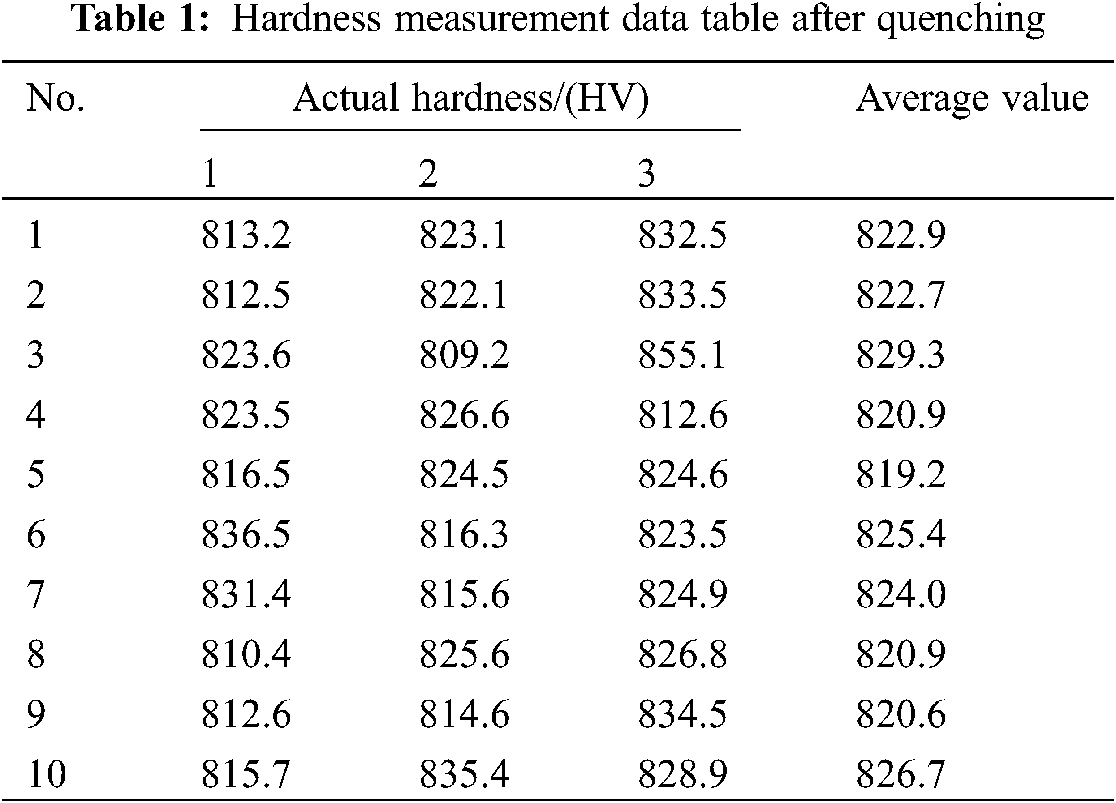
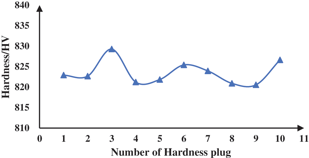
Figure 1: Measured value of hardness plug after quenching
From the preceding data, it can be found that the hardness plug after quenching had very uniform hardness values, with a deviation within ±10 HV, and the hardness of the experimental material met the requirements of HV ≥ 800.
The tempering test were carried out in the hardness plug tempering test in a constant temperature box, and the temperature was kept at 150°C to 450°C every 50°C for 2 h (the engine piston temperature was between 250°C and 300°C, and the measurement point was increased by 275°C within this range), with air-cooled in the furnace. The measured data was shown in Table 2.
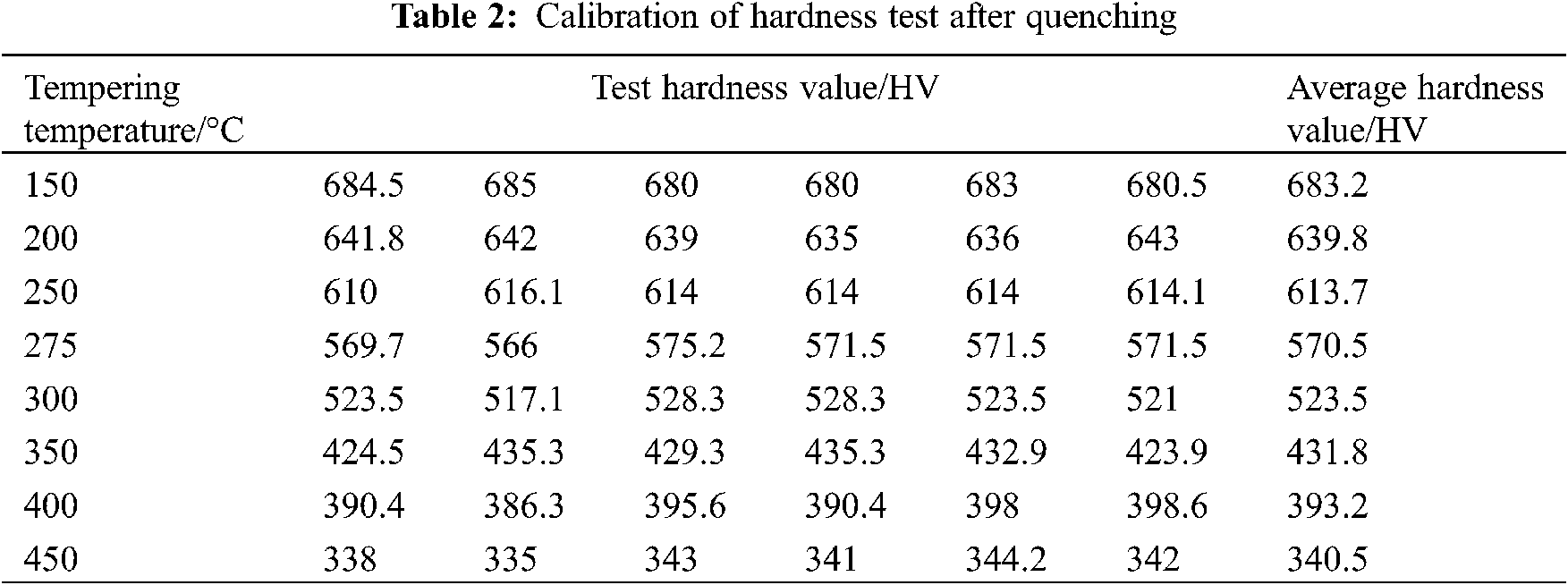
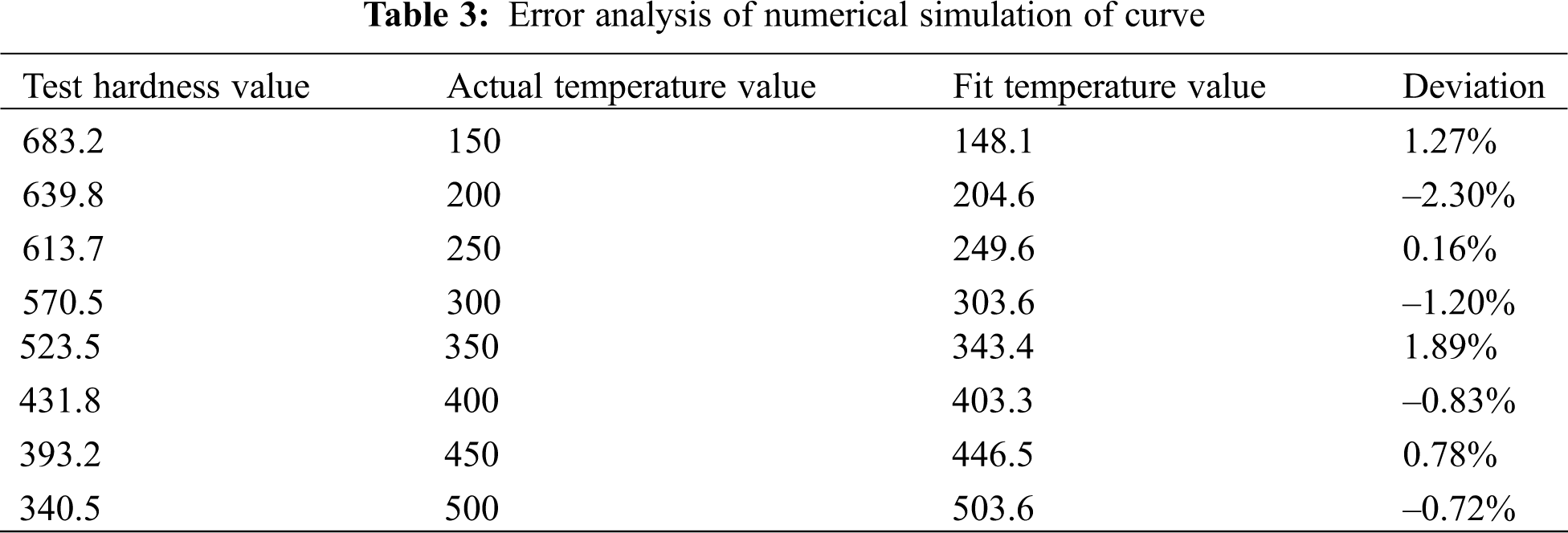
According to the data in Table 2, a characteristic curve of hardness-tempering temperature was drawn, as shown in Fig. 2. It can be seen from Fig. 2 and Table 3 that the change basically met the requirements of a linear change and the characteristic was relatively good.
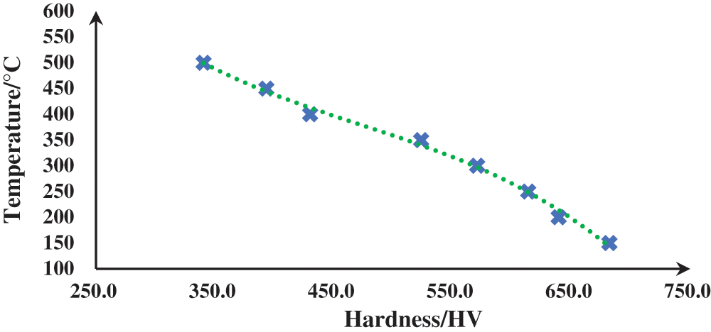
Figure 2: Numerical simulation of hardness-tempering temperature characteristic curve
2.2 Position of Piston Temperature Test and Engine Experiment
The main parameters of the piston were shown in Table 4. In order to ensure the accuracy of the experimental measurement, 20 measurement points were selected, and the hardness plug was installed according to the piston solution structure, shown in Fig. 3.
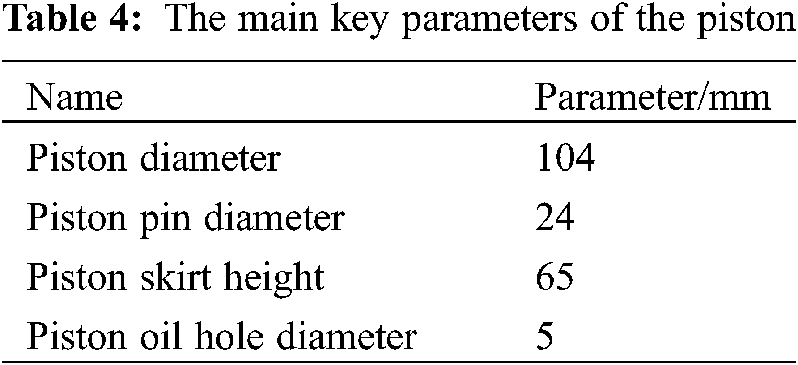
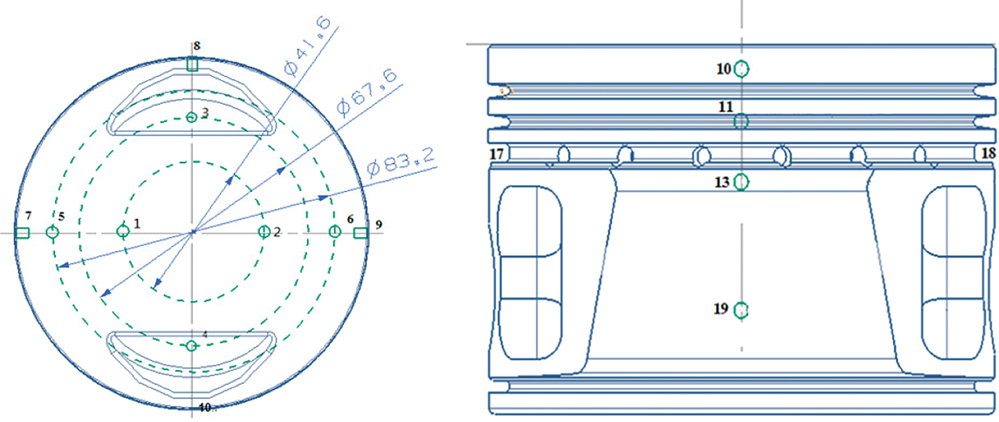
Figure 3: The location point of hardness plug on the side of the piston
The engine experiment of the piston temperature test was accomplished under certain conditions. The main parameters of the test conditions were shown in Table 5.
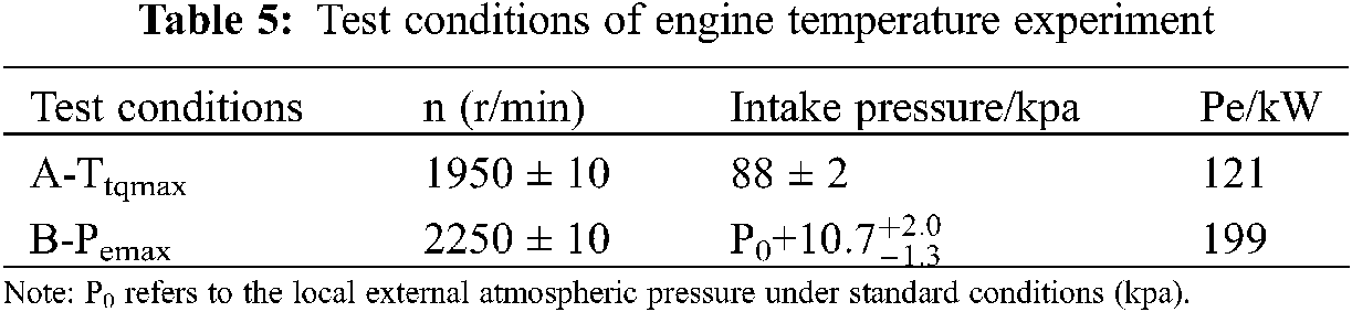
The temperature data under different working conditions between original piston and anodized piston was shown in the Figs. 4 and 5. It can be seen from the that under the conditions of maximum operating torque (as short for Ttpmax) and maximum operating power (as short for Pemax), most of the temperature values of the anodized piston were lower than those of the original piston, which indicated that the above process improvement had the effect of reducing the thermal load of the actual work of the piston.
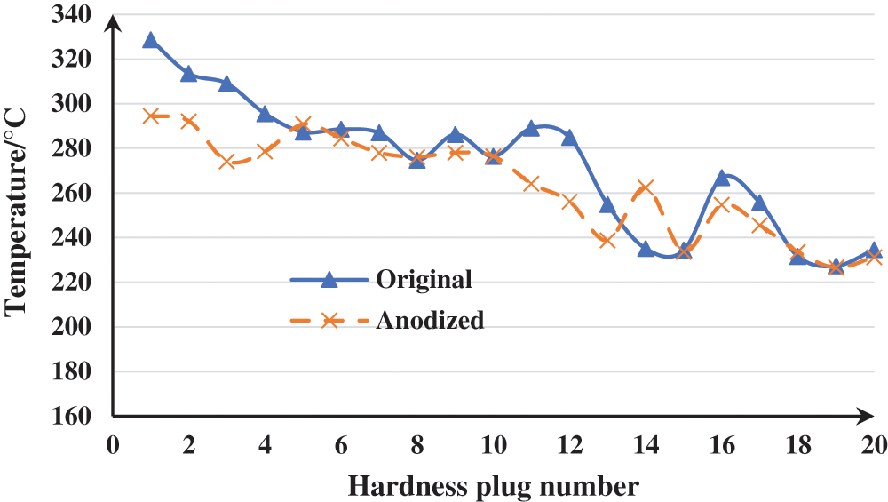
Figure 4: Temperature variation curves between Original piston and Anodized piston under Ttqmax
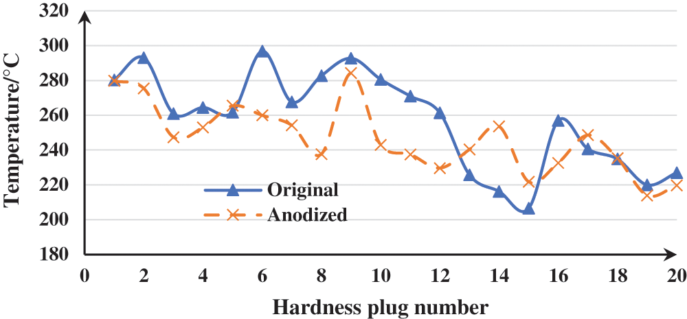
Figure 5: Temperature variation curves between Original piston and Anodized piston under Pemax
3 Finite Element Model of Piston and Boundary Conditions of Simulation Analysis
3.1 Piston Material and Finite Element Model
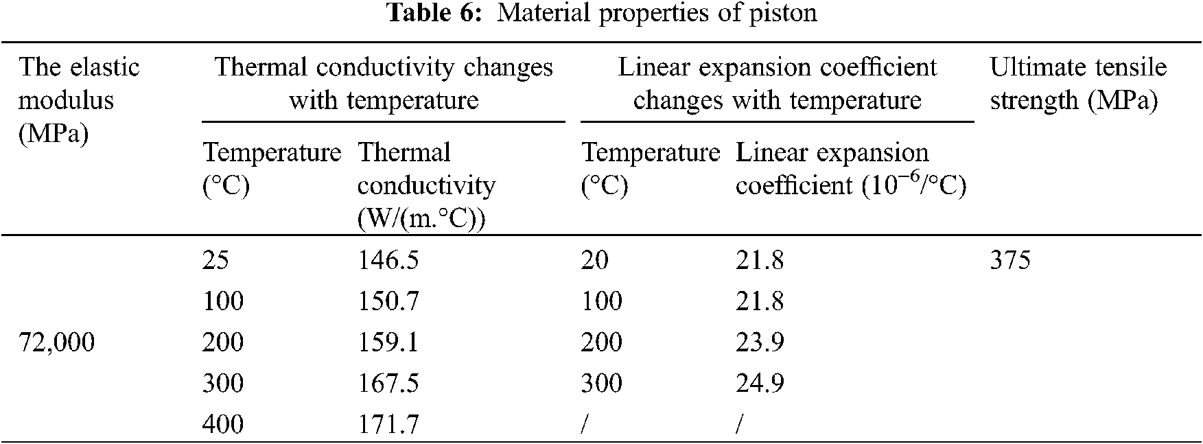
The piston material was forged aluminum 2A80, the density was 2.77 * 10^3 kg/m3, the elastic modulus of its material properties was 72 Gpa, the Poisson’s ratio was 0.33, and the tensile strength was 375 Mpa. The thermal conductivity and linear expansion coefficient were shown in Table 6.
The finite element analysis software of this time was ABAQUS, which was mainly considered to be a set of powerful engineering simulation finite element software, which can solve problems of not only relatively simple linear analysis but also many complex nonlinear problems [5]. The finite element mesh model of the piston was shown in Fig. 6. The piston model used in this calculation was a second-order tetrahedral mesh cell in compliance with the requirements of finite element analysis. The finite element parameter information contained 91517 nodes and 53440 elements.

Figure 6: Finite element mesh model of anodized piston
3.2 Boundary Conditions of Simulation Analysis
3.2.1 Boundary Conditions of the Top of the Piston and Internal Heat Transfer
According to the theory of periodic transient temperature fluctuations [6], the temperature of the top of the piston decreased rapidly along the normal direction of the top of the piston. Temperature fluctuation occurred only on the 1~2 mm surface of the piston top. Under the general specific working conditions, the temperature field on the top of the piston was defined as the stable Temperature field. According to the gas pressure of the engine acting on the piston crown and the volume of the cylinder [7], the instantaneous temperature of the cylinder was calculated using Eq. (1).
The relationship between the gas pressure in the cylinder and the crank angle was shown in Fig. 7.
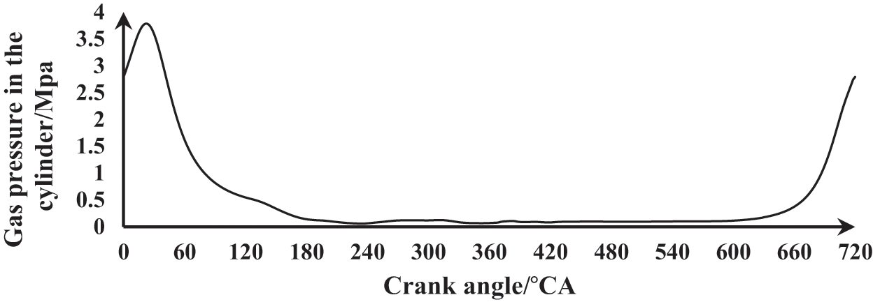
Figure 7: Variation curve of gas pressure in cylinder along with crank angle
The instantaneous heat release coefficient was calculated using the Eickelberg formula [8], scilicet
In the formula:
The internal heat transfer coefficient of the piston was affected by the temperature at the top of the piston and the airflow movement of the crankcase [9], which was generally expressed by Eq. (3)
In the formula:
3.2.2 Boundary Conditions of Heat Transfer between the Piston and Cylinder Wall
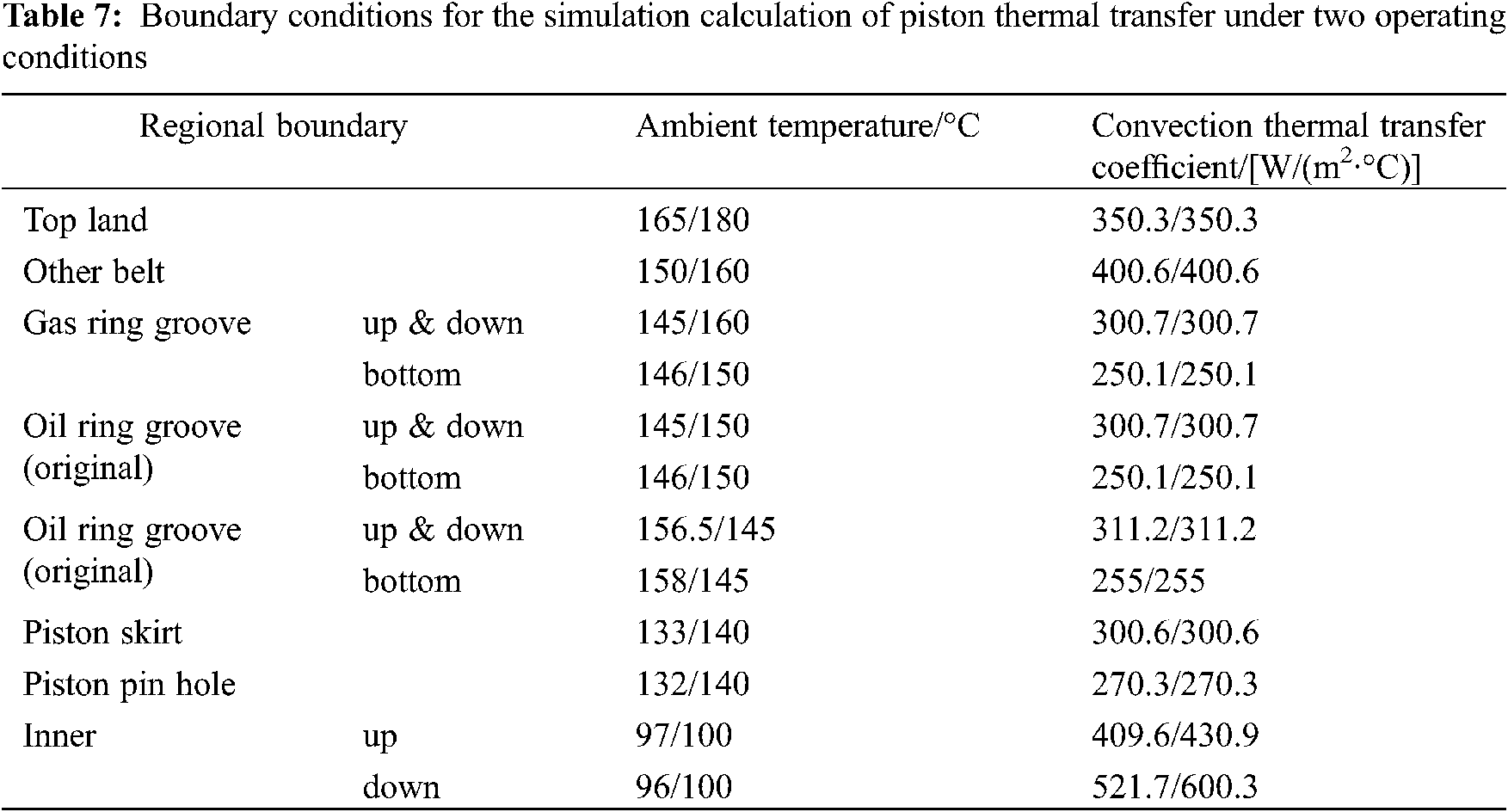
The heat transfer coefficients of the piston fire bank, piston ring groove and piston group were difficult to determine accurately [10]. Generally, empirical formulas were used to resolve the problem. Fig. 8 illustrated the heat transfer model. The heat transfer coefficient was affected by factors such as oil layer, piston ring, gas layer, and cylinder jacket thickness. The heat transfer coefficient can be shown in Table 7.

Figure 8: Thermal transfer model of piston and cylinder wall
The boundary conditions for the simulation calculation of piston heat transfer under various operating conditions were shown in Table 7.
4 Comparative Study of Computer Simulation and Experiment
4.1 Piston Thermal Load Calculation and Experiment
Figs. 9 and 12 illustrated the comparison curves between computer simulation and experiment under different working conditions. It can be seen from Figs. 9 to 12 that computer simulation was in highly agreement with the experimental data, and the error rate was less than 5%, which effectively validated the conclusion that the least squares method and the computer simulation have certain reliability and meet the requirements of engineering applications. It is quite normal for the difference between experiment and simulation. The possible reasons for the difference included the unstable test conditions, inaccurate experimental data, differences in boundary conditions measurement error and so on. However, from Fig. 11, it can be inferred that the change trend of experiment and simulation had a high degree of consistency, which reflected from the other side that the simulation had a certain credibility.
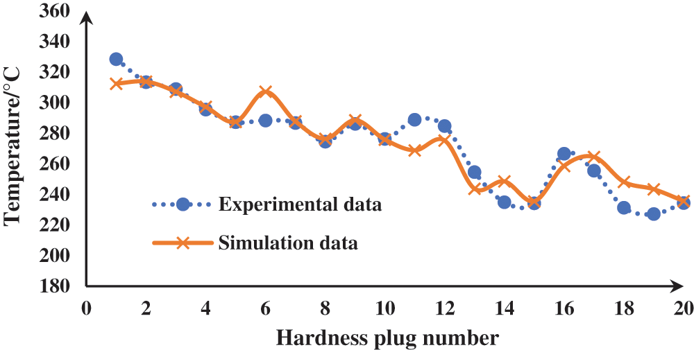
Figure 9: Comparison of experiment and simulation under Ttqmax condition of the original piston
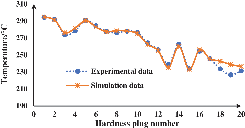
Figure 10: Comparison of experiment and simulation under Ttqmax condition of the anodized piston
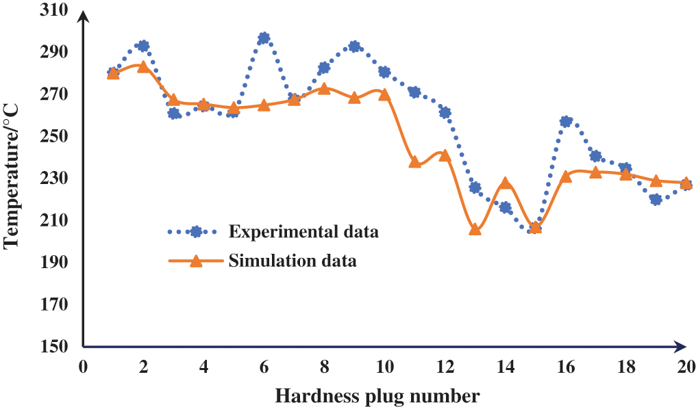
Figure 11: Comparison of experiment and simulation under Pemax of the original piston
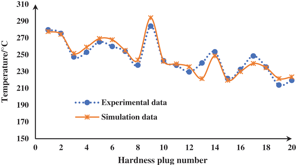
Figure 12: Comparison of experiment and simulation under Pemax condition of the anodized piston

Figure 13: Cloud diagram of the simulated temperature field under Ttqmax of the original piston
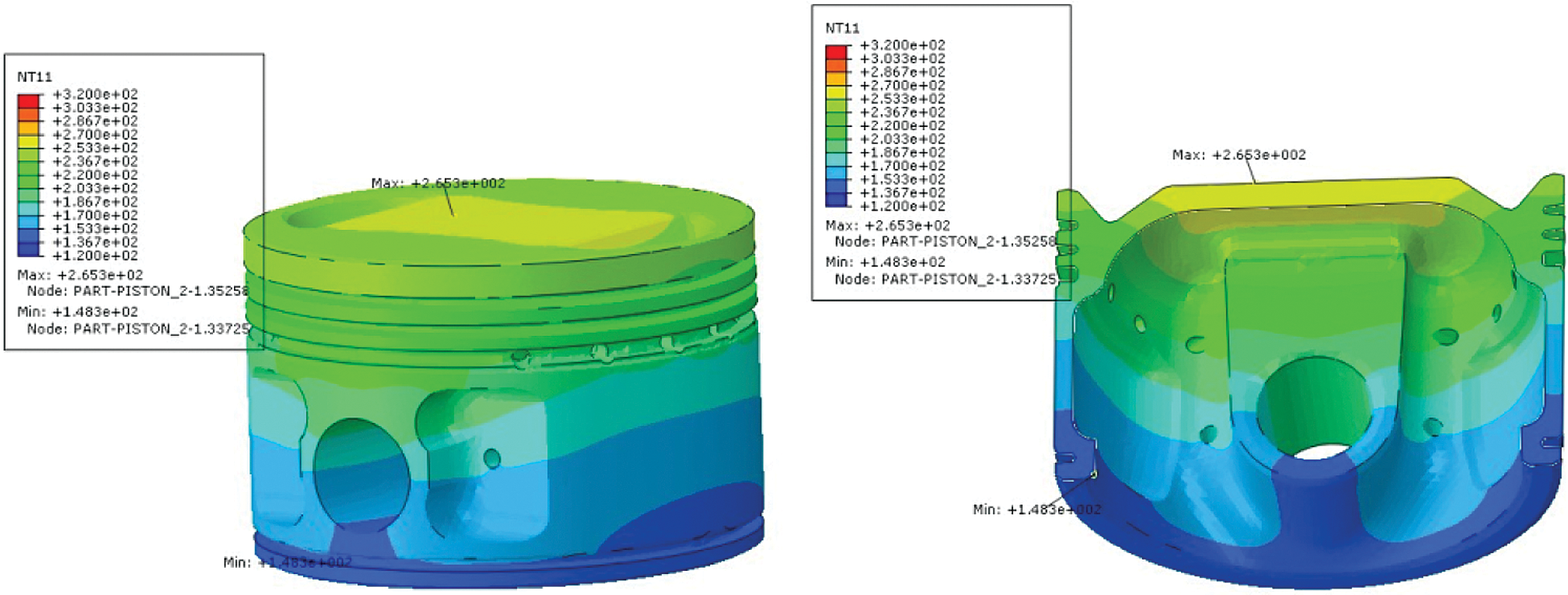
Figure 14: Cloud diagram of simulated temperature field under Ttqmax of the anodized piston
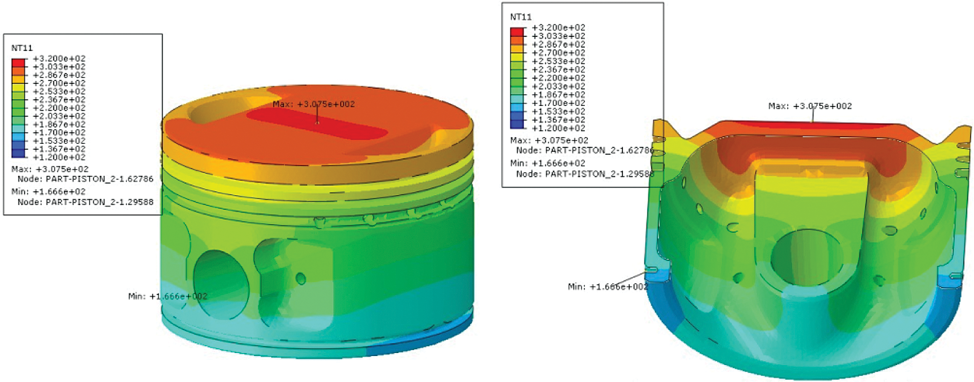
Figure 15: Cloud diagram of the simulated temperature field under Pemax of the original piston
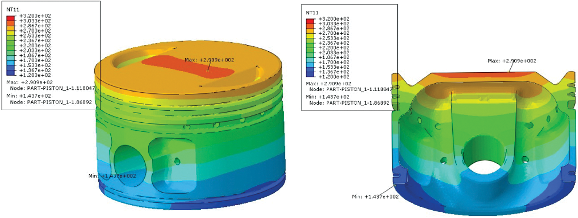
Figure 16: Cloud diagram of the simulated temperature field under Pemax of the anodized piston
Through computer simulation analysis of the piston temperature field data, as shown in Figs. 13–16 above, it can be seen that under the maximum torque condition, the temperature after optimization was 265.3°C, which was 51.9°C lower than the temperature before optimization (317.2°C), and the decrease rate was 16.36%. Under the maximum power condition, the temperature after optimization is 290.9°C, which was 16.6°C lower than the temperature before optimization (307.5°C), and the decrease rate was 5.4%. From the above simulation, it can be seen that by using the anodizing process, the maximum temperature of the piston can be reduced effectively no matter it is the maximum torque condition or the maximum power condition.
4.2 Analysis of Piston Thermal Stress
To meet the strength requirements of the material at high temperature, the thermal stress of the piston temperature field before and after optimization should be within 50 Mpa [11]. Figs. 17 to 20 had be shown the thermal stress analysis result between the original piston and the anodized piston under two different conditions. It can be seen from the cloud diagram that under either the Ttqmax condition or the pemax condition, the large thermal stress of the region after optimization was significantly reduced compared with before optimization, especially at the top inside the piston.

Figure 17: Thermal stress cloud under Ttqmax of the original piston

Figure 18: Thermal stress cloud under Ttqmax of the anodized piston

Figure 19: Thermal stress cloud under Pemax of the original piston
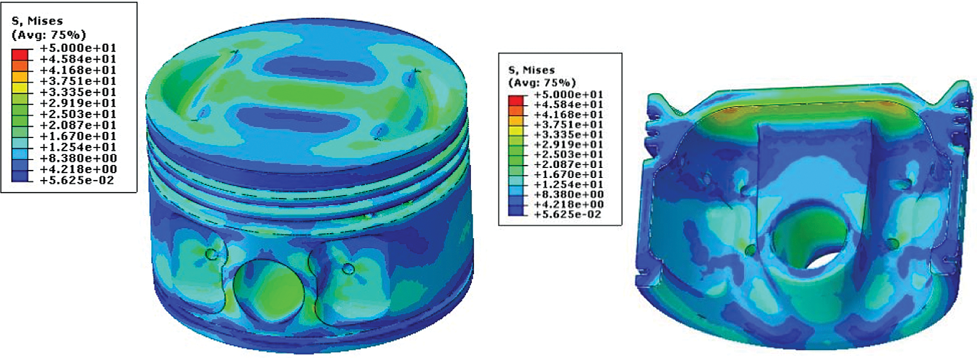
Figure 20: Thermal stress cloud under Pemax of the anodized piston
5 Calculation and Analysis of Fatigue under Typical Working Conditions
The piston with aluminum alloy material had highly dispersed strength. Generally, the conservative Goodman line was used, and the Haigh diagram is used to solve the fatigue strength [12]. According to the calculation results of the piston strength, the pistons of the master cylinder original and modified in the maximum continuous condition were selected for fatigue safety factor evaluation.

Figure 21: The distribution of safety factors of the inner cavity of the original piston of the master cylinder under the maximum continuous
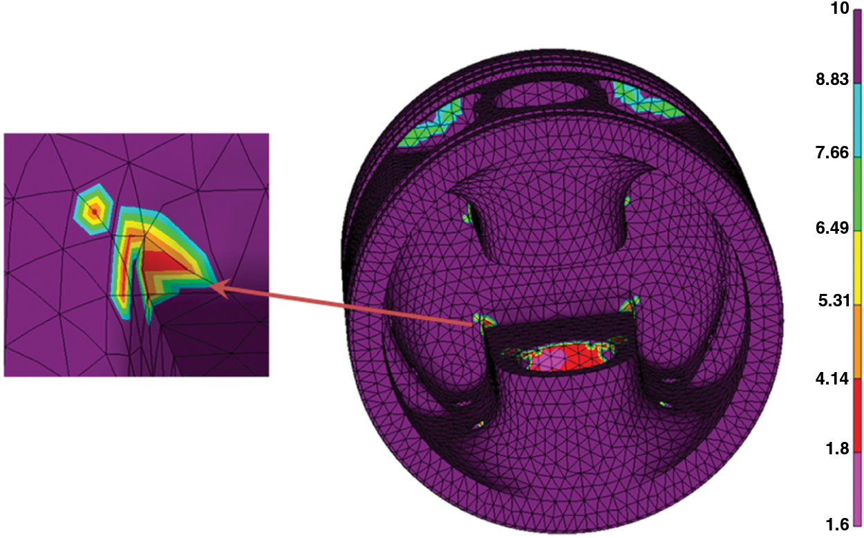
Figure 22: The distribution of safety factors of the inner cavity of the anodized piston of the master cylinder under the maximum continuous
The safety factor of the original piston above 1.8 was 98.61%, and the safety factor of modified piston above 1.8 was 99.13%. It can be seen that the safety factor was improved, but the results are not obvious. It can be seen from Figs. 21 and 22, the lower safety factor is mainly distributed at the edge of the oil return hole, the root of the piston cavity pin seat and the contact surface on the piston pin hole for original, as shown in Fig. 21. The lower safety factor is mainly distributed in the area where the root of the piston pin seat of the inner cavity intersects the weight reduction hole for modified piston, as shown in Fig. 22. The safety factor of the piston both original and modified can meet the requirements of material fatigue strength.
In this paper, the temperature field of the anodized piston is studied by means of hardness plug temperature test and numerical fitting method. Through a comparison between the CAE simulation and experimental test, combined with the heat transfer boundary conditions of the piston, and under the condition that the calculation error is less than 5%, the temperature field distribution of the original piston and the anodized piston under the maximum torque and the maximum power conditions is obtained.
The comparison between simulation and experiment shows that the maximum temperature of the anodized piston is 16.36% and 5.4% lower than the original piston under the maximum torque condition and the maximum power. The thermal stress of the temperature field of both pistons is within 50 Mpa, which meets the strength requirements of the material at high temperature. However, the area of thermal stress of the anodized piston is significantly lower than that of the original piston, especially at the top of the piston. Combined with the fatigue analysis data, it can be seen that the safety factor of the anodized piston greater than 1.8 is 99.13%. The anodizing process improves the surface mechanical properties to a certain extent and has a certain thermal insulation effect, which plays a positive role in reducing the piston temperature and thermal stress as well as in improving the reliability and life of the piston.
Acknowledgement: My gratitude would go to my dear family for their love and support throughout the years. I would also like to express my sincere gratitude to colleagues for their help and understanding during the experimental process of my thesis and for helping me to solve my difficulties.
Funding Statement: The authors received no specific funding for this study.
Conflicts of Interest: The authors declare that they have no conflicts of interest to report regarding the present study.
1. Caputo, S., Millo, F., Boccardo, G., Piano, A., Cifali, G. et al. (2019). Numerical and experimental investigation of a piston thermal barrier coating for an automotive diesel engine application. Applied Thermal Engineering, 162, 114–233. [Google Scholar]
2. Jalali, H., Abbassi, H. (2020). Analysis of the influence of viscosity and thermal conductivity on heat transfer by Al2O3-water nanofluid. Fluid Dynamics & Materials Processing, 16(2), 181–198. [Google Scholar]
3. Lu, Y., Zhang, X., Xiang, P., Dong, D. (2017). Analysis of thermal temperature fields and thermal stress under steady temperature field of diesel engine piston. Applied Thermal Engineering, 113, 796–812. [Google Scholar]
4. Zya, B., Kh, A., Rong, L. B. (2019). Enhanced high-temperature thermal fatigue property of aluminum alloy piston with Nano PYSZ thermal barrier coatings. Journal of Alloys and Compounds, 790, 466–479. [Google Scholar]
5. Kriraa, M., Souhar, K., Achemlal, D. (2020). Fluid flow and convective heat transfer in a water chemical condenser. Fluid Dynamics & Materials Processing, 16(2), 199–209. [Google Scholar]
6. Kim, G., Kang, Y. C., Woo, J., Kim, J. H., Yeon Cho, J. (2020). Efficient prediction of the temperature history of a hypersonic vehicle throughout the mission trajectory with an aerodynamic thermal load element. International Journal of Aeronautical and Space Sciences, 21(2), 363–379. [Google Scholar]
7. Wang, M., Pang, J. C., Zhang, M. X., Liu, H. Q., Li, S. X. et al. (2018). Thermo-mechanical fatigue behavior and life prediction of the Al-Si piston alloy. Materials Science & Engineering: A, 715, 62–72. [Google Scholar]
8. Selvam, R., Prakash, S., Gokulnath, R., Lillymercy, J. (2019). Experimental investigation of castor oil and methanol powered DI-CI engine with thermal barrier coated piston. International Journal of Vehicle Structures & Systems, 11, 466–470. [Google Scholar]
9. Shu, X., Ren, M. (2020). On the design and optimization of a clean and efficient combustion mode for internal combustion engines through a computer NSGA-II algorithm. Fluid Dynamics & Materials Processing, 16(5), 1019–1029. [Google Scholar]
10. Triveni, M., Panua, R. (2018). Numerical study of natural convection in a right triangular enclosure with sinusoidal hot wall and different configurations of cold walls. Fluid Dynamics & Materials Processing, 14(1), 1–21. [Google Scholar]
11. Hoche, F. X., Naze, L., Remy, L., Kster, A. et al. (2021). Effect of thermomechanical fatigue on precipitation microstructure in two precipitation-hardened cast aluminum alloys. Metallurgical and Materials Transactions A, 52, 3232–3246. [Google Scholar]
12. Totaro, P., Khusid, B. (2021). Multistep anodization of 7075–T6 aluminum alloy. Surface and Coatings Technology, 421(2), 127407. [Google Scholar]
 | This work is licensed under a Creative Commons Attribution 4.0 International License, which permits unrestricted use, distribution, and reproduction in any medium, provided the original work is properly cited. |