| Fluid Dynamics & Materials Processing |
DOI: 10.32604/fdmp.2022.016242
ARTICLE
Optimization of the Internal Circulating Fluidized Bed Using Computational Fluid Dynamics Technology
1School of Mechanical Engineering, Xi’an Jiaotong University, Xi’an, 710049, China
2Shenzhen Cellauto Automation Co., Ltd., Shenzhen, China
*Corresponding Author: Xiangxi Du. Email: rocket4@gmail.com
Received: 19 February 2021; Accepted: 09 June 2021
Abstract: The computational fluid dynamics (CFD) technology is analyzed and calculated utilizing the turbulence model and multiphase flow model to explore the performance of internal circulating fluidized beds (ICFB) based on CFD. The three-dimensional simulation method can study the hydrodynamic properties of the ICFB, and the performance of the fluidized bed is optimized. The fluidization performance of the ICFB is improved through the experimental study of the cross-shaped baffle. Then, through the cross-shaped baffle and funnel-shaped baffle placement, the fluidized bed reaches a coupled optimization. The results show that CFD simulation technology can effectively improve the mass transfer efficiency and performance of sewage treatment. The base gap cross-shaped baffle can improve the hydraulic conditions of the fluidized bed and reduce the system energy consumption. The cross-shaped baffle and funnel-shaped baffle can perfect the performance of the reactor and effectively strengthen the treatment in the intense aerobic process of industrial sewage.
Keywords: Internal circulating fluidized bed; computational fluid dynamics; optimization design; internal
Today, as water shortage and pollution get severe day by day, sewage treatment has become crucial in improving the earth’s environment and promoting the sustainable development of human beings. Research on sewage treatment has been deepening around the world for over 20 years, and the three-phase fluidized bed is the main part of sewage treatment. Based on the conventional sewage treatment methods, internal circulation fluidized bed (ICFB) integrated the biofilm process within and is applied in chemical fluidization technology, thus forming a piece of new biological treatment equipment [1]. This equipment performs superiorly in fluid mechanics, and also maintains mass transfer quality. Since this new type of equipment is still in the research stage, some data and design cannot be verified with the actual data but only compared with empirical data. The change of some factors like flow structure in the three-phase fluidized bed can be extremely complex with different internals and sizes. There is still no mature application of numerical analysis and quantitative expression of structure, and the theoretical design is very limited. The limitation is reflected in practical engineering.
In the 1990s, computational fluid dynamics (CFD) technology emerged. At that time, under the artificial solution background, computer calculation appeared as a shortcut. With the in-depth study of CFD, it can be used in more and more fields in daily life, such as automobile, aircraft, engine, and industrial manufacturing. An increasing number of domestic scholars are investigating CFD technology. CFD also plays an important role in which two or three-dimensional mass transfers are involved. Here, the CFD technology is used in environmental engineering, sewage treatment, to solve the limitations of conventional theory and provide a strong theoretical base for its further development. Based on the turbulence model and multiphase flow model, a fluidized bed’s flow performance can be more accurate, improving its efficiency and saving the time and cost for designing the ICFB.
Here, a cross-shaped base-gap internal component is designed and placed in the three-dimensional model of a quadrilateral fluidized bed utilizing CFD technology. The performance and potential of the ICFB are analyzed through a multiphase flow model, improving the traditional sewage treatment system. An improved scheme can be formed through the changes in simulation modeling data. Afterward, two kinds of internal components, cross-shaped and funnel-shaped, are designed to enhance the performance of a quadrilateral fluidized bed. Through the modeling analysis such as the turbulence model, an effective theoretical basis is provided for the industrial sewage treatment [2]. Obviously, CFD has many advantages, such as low cost, simple and straightforward experiments, and multiple simulation methods in getting about the fluid information. Today, the complexity and portability of experimental devices have been compensated and solved with the development of CFD and the popularization of computers. Three innovations are introduced here. (1) CFD simulation technology is applied to improve the ICFB and is used in the three-dimensional simulation, providing a further optimization space for the design of the ICFB. (2) To improve the performance of the traditional sewage treatment system, the cross-shaped baffle is designed in the base gap area using the CFD method, thus, proving the CFD’s optimization effect on the quadrangle ICFB. (3) New cross-shaped baffles and funnel-shaped baffles are established and placed in a quadrilateral ICFB for coupling optimization. This innovative design improves and optimizes the performance of industrial sewage treatment.
2.1 Structure and Experimental Study of ICFB
It has always been difficult to treat high concentration and toxic organic wastewater, and a three-phase fluidized bed is very advantageous in this area. As a new structure, the research of ICFB will promote the improvement and innovation of traditional technology. In a fluidized bed reactor, different circulating fluidized beds are divided according to different ways of fluid circulation. Its circulation model is conducive to the interphase mass transfer and reaction process, which is greatly different from the traditional reactor. Fig. 1 shows the operation diagram of the ICFB. Apparently, the fluid circulates in the reactor.
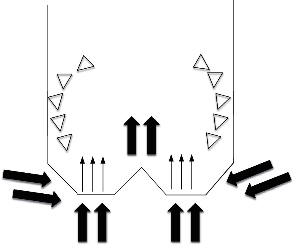
Figure 1: Operation diagram of ICFB
The ICFB has been recognized and studied for nearly 20 years. Under manual computation, the ICFB shows great complexity in operation and a fixed flow. Without systematic theoretical guidance, people can only rely on the experiences of those designers. Thus, experiments and research on ICFB become an urgent need put on the shoulders of researchers all around the world. In recent years, researchers have collected effective data through plenty of experiments and obtained many conditions in favor of the application of ICFB in real life.
CFD has broken through from two-dimensional flow to three-dimensional flow with the development of computer technology. Abiding by the three laws of physics: the law of conservation of mass, the law of conservation of momentum, and the law of conservation of energy, the mathematical relationship in the three laws of physics is expressed in discrete algebraic form based on the advantages of CFD in three-dimensional flow. Under the control equations of the three laws, the flow of simulated fluid is studied utilizing CFD through the computer. The system is modeled through numerical simulation after some information about a specific fluid is obtained.
After the mass difference value between the inflow control body and outflow, and the control body is calculated, the value is then compared with the increased mass value of the related fluid, and the mass conservation law is obeyed if these two values are the same. The momentum conservation law is obeyed if all the external forces acting on a body are equal to momentum’s rate-of-change in time in the fluid system. Likewise, the energy conservation law is obeyed, if the amount of increased and decreased energy in the whole process is the same.
At present, CFD software, such as STAR-CD, Fluent, and CFX are widely used in various fields. CFD is developing comprehensively, no longer just for calculation [3]. The grid generation, algorithm structure, and other content show that CFD-related research has become a multidisciplinary integrated science, and has achieved good results in many fields, such as environmental engineering, chemical engineering, and aerospace.
The basic CFD models involved hereon include the turbulence model and multiphase flow model.
To distinguish from the viscous fluid, the Reynolds number (Re) is used as the criterion. If Re is less than 2,000, it is judged as laminar flow; if Re is larger than 2,000, it is judged as turbulent flow.
The above is the equation of Reynolds number, where Re represents Reynolds number, ρ represents density, V represents volume, D represents diameter, and μ represents viscosity.
Compared with the ordered state of laminar flow, turbulent flow shows a disordered chaotic state. In practical engineering, the Reynolds averaged N-S (RANS) method is adopted [4], because the other two methods, large eddy simulation (LES) and direct numerical simulation (DNS), cannot be used in practical engineering. With underdeveloped computer technology, the direct numerical simulation of turbulence based on the NS equation is used, arising so many disadvantages. RANS method can be utilized to simulate the contribution of pulsating motion to translational motion, which becomes an effective and feasible method to solve engineering problems.
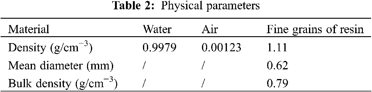
Different flows correspond to different accuracy requirements and time costs. Therefore, how to choose a suitable turbulence model is crucial. The definition and usage of each turbulence model are explained in detail in Table 1, from which the most suitable model can be selected.
Engineering calculations tend to use the Reynolds average N-S equation method (RANS) to decompose the transient turbulent flow into average motion and pulsating motion, and express the latter through the Reynolds stress term. Based on the requirements of accuracy and the performance of the computer, the Standard κ-ε turbulence model, which is recognized as the most widely used eddy viscosity model. This model consists of the turbulent kinetic energy equation and the diffusion equation κ, which are
In Eqs. (2) and (3), Gk: the production term of turbulent kinetic energy k due to gradient change of average velocity; Gb: the generation term of turbulent kinetic energy k caused by buoyancy change; Ym: the effect of pulsation expansion in compressible turbulence; Qk: the Prandtl number corresponding to turbulent momentum k; Qe: the Prandtl number corresponding to turbulent momentum ε. C1ε, C2ε and C3ε are constants. When the direction of the mainstream is parallel to that of gravity.
In the flow field, the same kind of material with the same boundary conditions and dynamic characteristics becomes the phase. The phase of matter is generally divided into the gas phase, liquid phase, and solid phase. At present, the single-phase turbulence model is only used in the calculation of the basic phase turbulence model. When mixing occurs, more phases need to coexist in a fluid motion to establish a turbulence model, such as the mixing of gas and liquid phase, liquid and solid phase, and gas and solid phase [5]. Generally, the mixture of two phases is more common. The common multiphase flow models include the VOF model, mixture model, and Euler model. The most suitable flow model should be selected according to experience, in response to different fluid flow. Thus, more related phase flow problems will be solved in practical application.
Different models are applied in different scopes. The most common way to distinguish these three models is: ① VOF model is selected when the stratified flow, free-surface flow, and large bubble flow in liquid are to be predicted. ② Mixture model should be selected for simulation analysis of bubble flow, settlement, and cyclone separator. ③ The Eulerian model is needed for the simulation of a bubble column, particle suspension, and floating.
The medium flowing in the biological fluidized bed reactor is wastewater. The purpose of this study is to obtain the internal flow status of the reactor. Therefore, the sewage is simplified to a single phase. The phase mixing of the flow in the fluidized bed is intense. Flow resistance can be utilized. Therefore, the Eulerian-Eulerian multiphase flow model is selected to solve the momentum and continuity equations of gas and liquid phases. The pressure term is coupled with the interface exchange coefficients. This model established a set of n momentum equations and continuity equations, and solved each phase. The control equation is as follows:
The used basic phase and subordinate phase are water and air in standard condition respectively.
2.3.3 Operating Conditions and Boundary Conditions
The operating atmospheric pressure is 101325 Pa, the gravity acceleration is 9.81 m/s2, and the direction is downward along the z axis.
The entire bottom inlet is set as a speed inlet. Air phase content is 1. Assuming that the bubble diameter is uniform 3 mm. To treat typical biological wastewater anaerobically as aerobic, 0.5 cm/s, 1 cm/s, 2 cm/s, 3 cm/s are selected as four groups of inlet velocity (on rising section). The top outlet of the reactor is pressure outlet. Subordinate phase content of 1 is used as reflux condition. Neumann boundary condition is applied to the symmetric surface of the model.
The initial height of the liquid level is set at 900 mm. Above the liquid level is air.
2.3.4 Solution Parameter Setting
SIMPLE algorithm is used to solve the velocity-pressure coupling equation. The first-order upwind scheme is used as a discrete scheme for momentum, turbulent kinetic energy and turbulent dissipation rate. QUICK scheme is used as the discrete scheme of volume fraction. Meanwhile, the default relaxation factor of Fluent is used. The unsteady process is simulated. The time step is 0.003s, and each time is iterated 50 times. The convergence standard residual of all variables is set to 1 × 10⁻³. The criterion for judging steady state is computational convergence. When the inlet and outlet flow and the liquid circulation velocity and gas holdup of the monitoring surface fluctuate within 5%, the iterative calculation can be stopped.
All calculations are paralleled on Intel Core i7 3.5 GHz four-core CPU, 16 GB memory computers. The calculation time of each data is about 150 h.
3.1 Establishment of CFD Simulation Method
In the two-dimensional numerical simulation, the Euler model is used to simulate the gas-liquid-solid three-phase ICFB. First, the platform of the ICFB is established through CFD software. Second, after the corresponding CFD simulation method is established, the grid size factor is added and then analyzed and studied as a whole to see if it interferes with the accuracy of CFD simulation results. Third, the ventilation volume is observed, and whether the gas holdup and liquid circulation speed are interfered with is analyzed. Accordingly, the suitable conditions are selected for mass transfer and flow in the ICFB. Accurate experimental data can verify the suitable CFD simulation method. The physical parameters of the research objects are listed in Table 2.
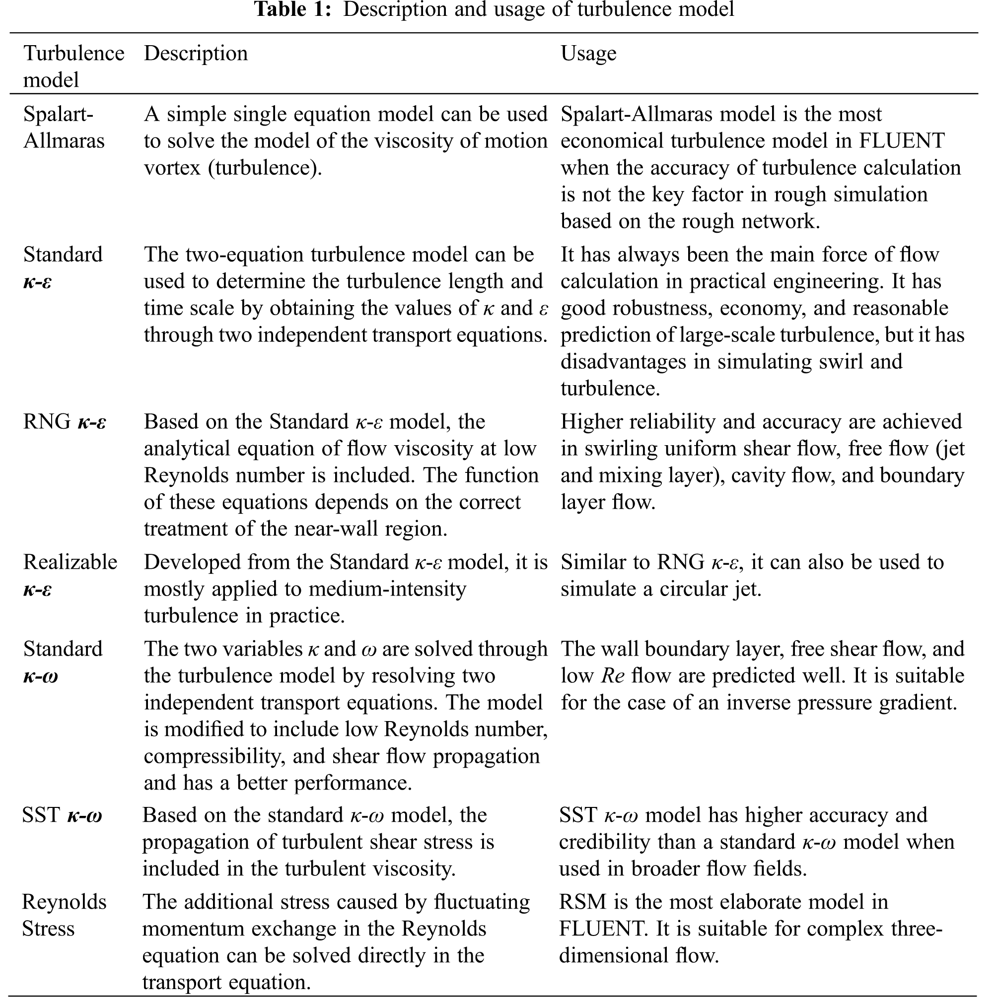
First, the physical model of the research object is established through Gambit processing software. This step requires preparation for CFD simulation [6]. Then, Fig. 2 is the fluidized bed reactor model after meshing.
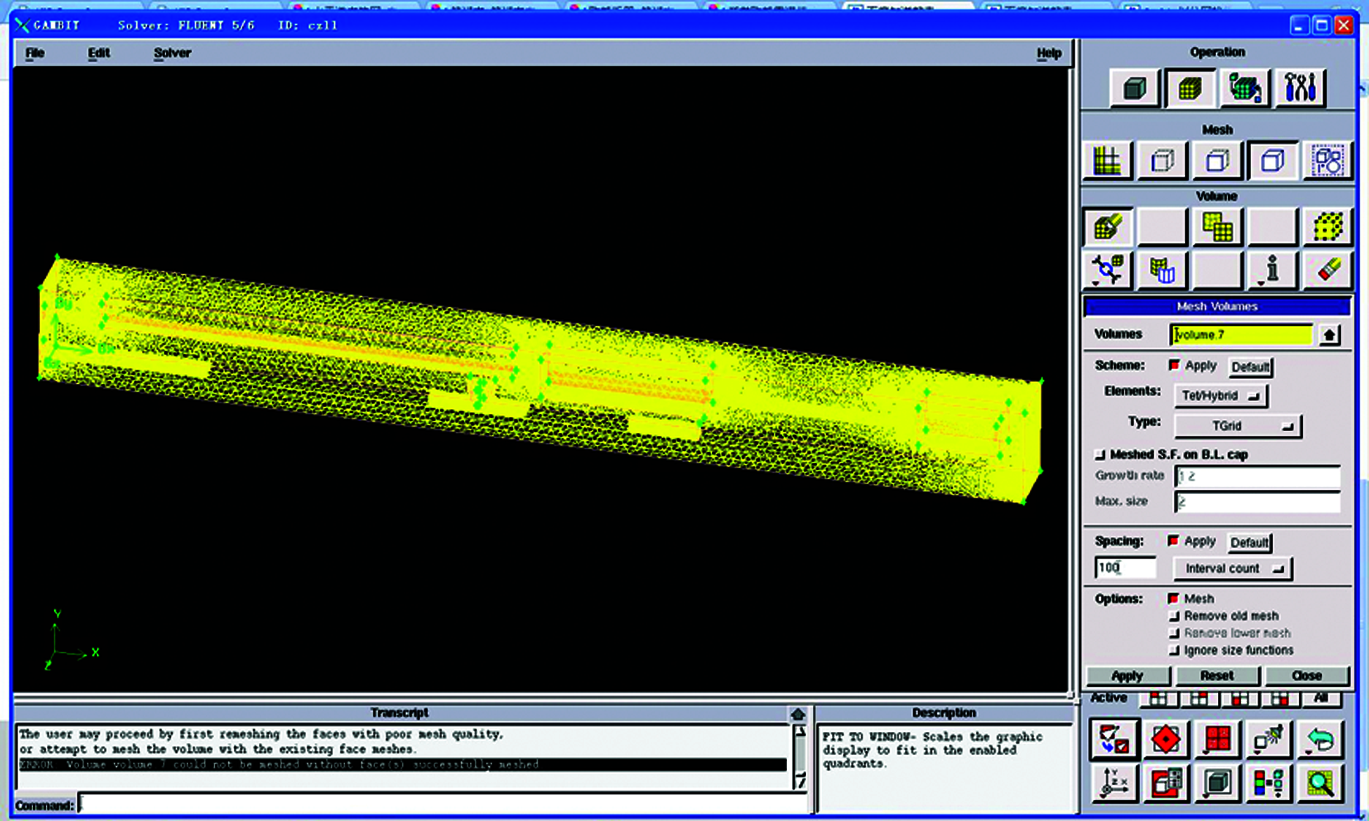
Figure 2: Model of fluidized bed reactor after meshing
In the numerical simulation, Fluent 6.3.26 is used to import the grid file created by Gambit. First, the separation solver and calculation model are selected; then, the operating environment, boundary conditions, and initial conditions are set; finally, the parameter setting is solved.
3.2 Analysis of Network Independence
In the above experiments, the importance of grid division should be verified. The experimental analysis on its independence is needed to determine whether the simulation results change according to the grid accuracy. Six sizes of 0.5, 1, 2, 3, 4, and 5 are designed in the experiment. The gas holdup and liquid circulation rate are compared in the ascending and descending regions [7]. The experimental results can analyze the different results of CFD simulation changes under different grid accuracy. Fig. 3 shows the effect of grid size on gas content, and Fig. 4 shows the effect of grid size on liquid circulation rate.
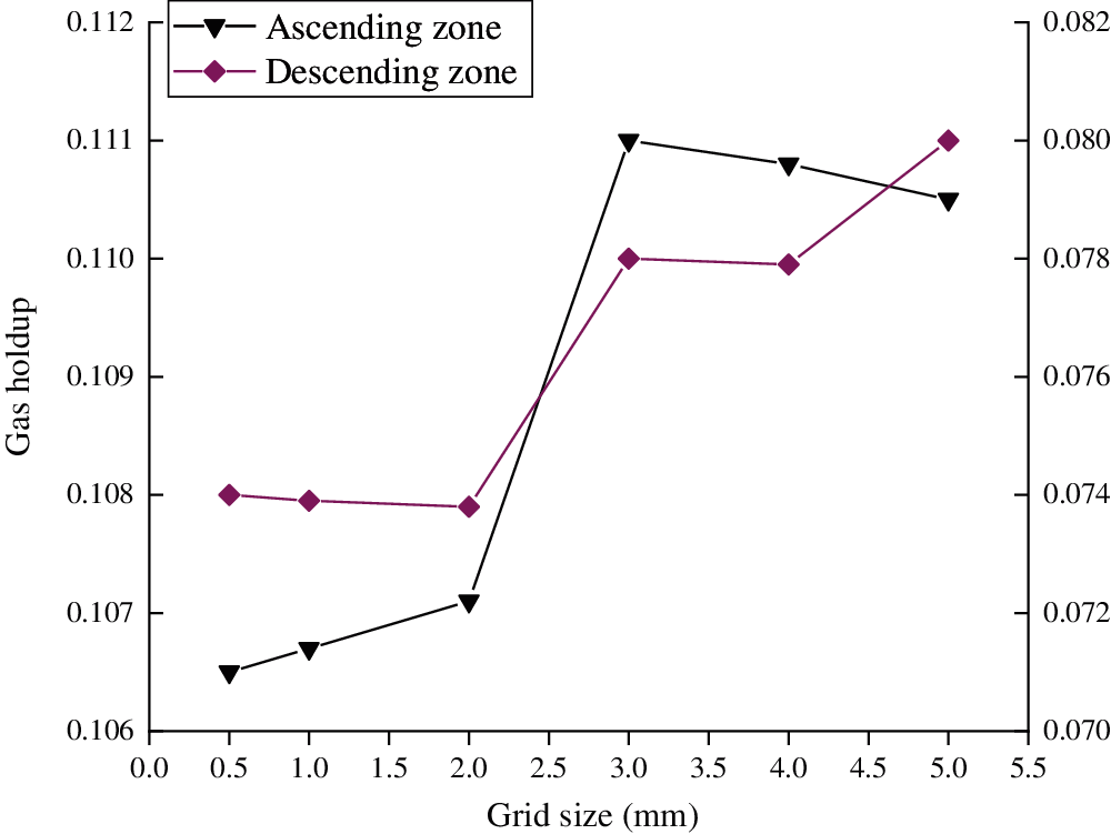
Figure 3: Influence of grid size on gas content
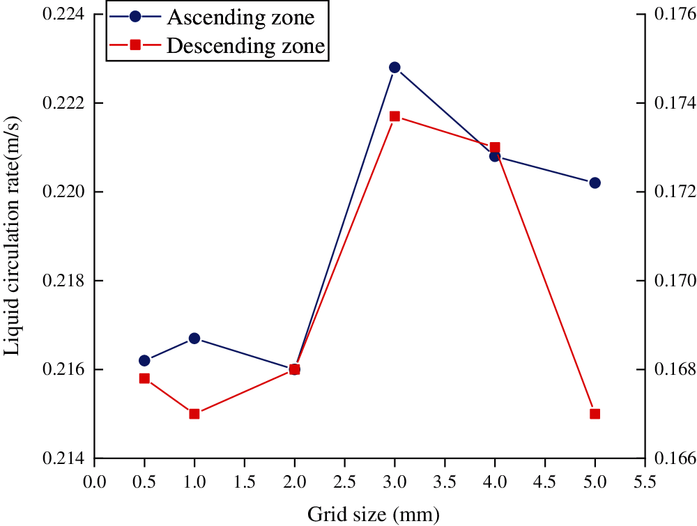
Figure 4: Effect of grid size on liquid circulation rate
Cleary, with the decrease of grid size, other numerical values change. To be specific, the smaller the size is, the larger the number of grids is, and the more memory and time are consumed. Concurrently, the most economical computing resource and time are simulated in a 2 mm grid.
3.3 Research on the Improved ICFB with Cross-Shaped Internals in the Base Gap
The innovative cross-shaped baffle [8] internals in the base gap can be used in the three-dimensional model of the fluidized bed to solve the high cost and large error of physical experiments. On this basis, it is verified whether the hydrodynamic performance of the reactor can be improved. The Eulerian-Eulerian two-fluid model is adopted to simulate by analyzing the corresponding characteristics of different CFD models and including the gas-liquid combination mode in the experiments. Thus, the change of hydraulic characteristics before and after placing the baffle is studied.
Apparently, under isothermal conditions, the circulating velocity in the fluidized bed increases by about 16% with the interaction of the two fluids, so the hydrodynamic performance of the fluidized bed can be greatly improved by placing the cross-shaped baffle in the base gap. These improved performances can solve the problem of short sludge retention time in sewage treatment, and strengthen the sludge load of the fluidized bed. Concurrently, under different hydraulic conditions in the fluidized bed, the base gap cross-shaped baffle can reduce the energy consumption of the system and improve the performance of sewage treatment.
3.4 Research on Improved ICFB with Cross-Shaped and Funnel-Shaped Internals
The innovated cross-shaped and funnel-shaped internals are placed in the base gap to analyze the improved performance of the ICFB [9]. The turbulence model and multiphase flow model are selected as the evaluation model. Gas holdup and gas-liquid mass transfer can be obtained from the operation of wastewater treatment reactor, and these are the two critical factors in reducing energy consumption and improving efficiency [10]. The key research purpose of this experiment lies in whether the non-degradable substances in industrial sewage can be decomposed after the insertion of cross-shaped and funnel-shaped internals.
The funnel-shaped baffle and cross-shaped baffle show good performance in the experiment to improve the mass transfer and fluidization quality of the gas-liquid phase. The fluidization quality of the improved ICFB is enhanced after the coupled optimization. The retention time in the gas phase is also extended [11]. Consequently, some tough issues, such as intense aerobic processes and low energy consumption requirements, can be solved and improved in the process of industrial sewage treatment.
Here, an improved experimental model suitable for the ICFB is obtained through the research and analysis of the CFD model from the two-dimensional model to the three-dimensional model. Compared with the traditional ICFB for sewage treatment, multiple internal placement experiments are added to make the treatment of industrial sewage more efficient. The CFD method can be used for numerical simulation analysis. The results show that the CFD simulation method can improve the performance of sewage treatment from many aspects and can further guide its industrial application. Through the experimental data, the improved effect of the fluidized bed is analyzed by placing a cross-shaped baffle in the base gap. Consequently, both hydraulic conditions and system energy consumption of fluidized beds are greatly improved. The experiments of the cross-shaped baffle and funnel-shaped baffle show that the coupling can optimize the mass transfer and fluidization quality of gas-liquid two-phase. Obviously, the CFD can accurately simulate the changes of the ICFB under different conditions including physical law like gas-liquid two-phase fluid movement and mass transfer. It also plays an active role in the structure optimization of ICFB.
Due to the urgency for sewage treatment, a new type of biological treatment equipment is desperately needed globally. The conventional activated sludge process and biofilm process of ICFB are improved utilizing the CFD simulation technology. Still, there is considerable room for improvement, and there are also some limitations and deficiencies in this research process that can be further discussed in future studies. (1) More accuracy is needed in a more complex practical situation for an ICFB, which involves a lift model and virtual mass force model. (2) Only the two-phase flow model is involved here. The space-time distribution of the influence of multiphase structure can be solved if the gas-liquid-solid three-phase flow model can be added in future research.
Funding Statement: The authors received no specific funding for this study.
Conflicts of Interest: The authors declare that they have no conflicts of interest to report regarding the present study.
1. Dubinin, A. M., Mavrin, S. P. (2016). Optimum parameters of the air gasification of coals in a circulating fluidized-bed gas generator with a stagnant layer. Solid Fuel Chemistry, 50(3), 177–183. DOI 10.2112/si93-120.1. [Google Scholar] [CrossRef]
2. Atimtay, A. T., Kayahan, U., Unlu, A., Engin, B., Varol, M. et al. (2017). Co-firing of pine chips with turkish lignites in 750 kwth circulating fluidized bed combustion system. Bioresource Technology, 224,601–610. DOI 10.1016/j.biortech.2016.10.065. [Google Scholar] [CrossRef]
3. Upadhyay, M., Park, H. C., Hwang, J. G., Choi, H. S., Jang, H. N. et al. (2017). Computational particle-fluid dynamics simulation of gas-solid flow in a circulating fluidized bed with air or O2/CO2 as fluidizing gas. Powder Technology, 318, 350–362. DOI 10.1016/j.powtec.2017.06.021. [Google Scholar] [CrossRef]
4. Palkar, R. R., Patnaikuni, V. S., Shilapuram, V. (2018). Step by step methodology of designing a liquid–solid circulating fluidized bed using computational fluid dynamic approach. Chemical Engineering Research and Design, 138, 260–279. DOI 10.1016/j.cherd.2018.08.031. [Google Scholar] [CrossRef]
5. Wüstenhagen, C., Pfensig, S., Siewert, S., Kaule, S., Grabow, N. et al. (2018). Optimization of stent designs regarding the thrombosis risk using computational fluid dynamics. Current Directions in Biomedical Engineering, 4(1), 93–96. DOI 10.1515/cdbme-2018-0024. [Google Scholar] [CrossRef]
6. Serra, N, Semiao, V. (2021). ESIMPLE, a new pressure–velocity coupling algorithm for built-environment CFD simulations. Building and Environment, 204(1), 108170. [Google Scholar]
7. Zhang, Y. W., Lei, F. L., Xiao, Y. H. (2019). Influence of solids circulation flux on coal gasification process in a pressurized high-density circulating fluidized bed. Journal of Thermal Science, 28(1), 99–107. DOI 10.1007/s11630-018-1059-3. [Google Scholar] [CrossRef]
8. Cloete, J. H., Khan, M. N., Cloete, S., Amini, S. (2019). Simulation-based design and economic evaluation of a novel internally circulating fluidized bed reactor for power production with integrated CO2 capture. Processes, 7(10), 723. DOI 10.3390/pr7100723. [Google Scholar] [CrossRef]
9. Zhang, H., Lu, Y. (2020). A computational particle fluid-dynamics simulation of hydrodynamics in a three-dimensional full-loop circulating fluidized bed: Effects of particle-size distribution. Particuology, 49, 134–145. DOI 10.1016/j.partic.2019.02.004. [Google Scholar] [CrossRef]
10. Khongprom, P., Ratchasombat, S., W. N. Han, W., Bumphenkiattikul, P., Limtrakul, S. (2020). Scaling of a catalytic cracking fluidized bed downer reactor based on computational fluid dynamics simulations. RSC Advances, 10(5), 2897–2914. DOI 10.1039/c9ra10080f. [Google Scholar] [CrossRef]
11. Mallick, D., Mahanta, P., Moholkar, V. S. (2020). Co-gasification of biomass blends: Performance evaluation in circulating fluidized bed gasifier. Energy, 192, 116682.1–116682.10. DOI 10.1016/j.energy.2019.116682. [Google Scholar] [CrossRef]
12. Su, X., Wang, C., Lan, X., Pei, H., Mao, X. et al. (2020). Flow of high solids density suspensions in an 18 m high circulating fluidized bed. Industrial and Engineering Chemistry Research, 59(3), 1336–1349. DOI 10.1021/acs.iecr.9b05893. [Google Scholar] [CrossRef]
 | This work is licensed under a Creative Commons Attribution 4.0 International License, which permits unrestricted use, distribution, and reproduction in any medium, provided the original work is properly cited. |