| Fluid Dynamics & Materials Processing |
DOI: 10.32604/fdmp.2022.019605
ARTICLE
A Mixed Radiative-Convective Technique for the Calibration of Heat Flux Sensors in Hypersonic Flow
1Department of Industrial Engineering, University of Naples, Naples, 80125, Italy
2Department of Mechanical and Aerospace Engineering, University of Strathclyde, Glasgow, G1 1XJ, UK
3Cheminox srl, San Vito dei Normanni (BR), 72019, Italy
*Corresponding Author: Marcello Lappa. Email: marcello.lappa@strath.ac.uk
Received: 01 October 2021; Accepted: 29 October 2021
Abstract: The ability to measure the very high heat fluxes that typically occur during the hypersonic re-entry phase of space vehicles is generally considered a subject of great importance in the aerospace field. Most of the sensors used for these measurements need to be checked periodically and re-calibrated accordingly. Another bottleneck relates to the need to procure thermal sources that are able to generate reliable reference heat fluxes in the range between 100 and 1000 kW/m2 (as order of magnitude). In the present study, a method is presented by which, starting from a calibration system with a capacity of approximately 500 kW/m2 only, heat fluxes in the range of interest for hypersonic applications are generated. The related procedure takes advantage of established standards for the characterization of a radiative heat flux. It also builds on the hybrid radiative-convective nature of typical hypersonic heat fluxes and the yet poorly explored possibility to use convective sources of heat to produce high-intensity fluxes. The reliability of such a strategy has been tested using a high enthalpy supersonic flow facility relying on an electric arc-heater and pure Nitrogen as work gas. Stagnation-point heat fluxes have been successfully measured (with reasonable accuracy) in the range between 600 and 1500 kW/m2 for values of the centerline enthalpy spanning the interval from to 6 to 24 MJ/kg.
Keywords: Photometry; heat flux sensor; calibration facility; radiative source; convective source
Hypersonic re-entry is (by definition) the last stage of any space mission in which a spacecraft finally undergoes a controlled entry into the atmosphere of a planet (Earth or other planets of the Solar System) at very high speed. This phase should be regarded as one of the most demanding stages of the entire mission for a series of concurrent factors. Among them it is worth mentioning the ‘mechanical load’ the vehicle is subjected to (Zare-Behtash et al. [1] and references therein). The vehicle structure obviously undergoes strong inertial stresses due to the significant deceleration produced by its interaction with the atmosphere, which behaves as an ‘aerobrake’. Not least, frictional effects are responsible for substantial aerodynamic heating (Wang et al. [2] and references therein). More specifically, a significant amount of the initial kinetic energy possessed by the spacecraft is directly converted in internal energy with a remarkable ensuing increase in the temperature of the gas surrounding the vehicle (thermal load). The formation of shock waves also contributes to this process resulting in a significant increase of the gas temperature before it reaches the surface of the vehicle (see, e.g., Zhou et al. [3]).
All these factors play a role in making the design of a relevant and suitable Thermal Protection System (TPS) an aspect of great importance in this field.
Although, recent progress in theoretical and mathematical aspects (models for gas-dynamics where the chemical reactions enabled by the high temperatures of the hypersonic regime are explicitly taken into account), and available computational resources (parallel and massively parallel computers) have made Computational Fluid Dynamics (CFD) techniques increasingly cost effective in comparison to experiment-based methods of analysis, most of the research conducted in this area still relies heavily on dedicated ‘tests’ conducted using wind tunnels and related facilities.
A simple rationale for such a widespread practice can obviously be found in the (still unresolved) difficulties met by researchers when the complex behavior of the gas and of the protective (solid) materials have to be modeled (numerically simulated) at the same time and in a reasonably ‘coupled’ way. Chemical reactions occurring in the fluid and solid phases, ‘catalytic behaviors’ taking place at the surface separating these phases, excitation of additional microscopic degrees of freedom in the fluid and erosion, void formation and/or crack propagation in the solid are just examples of the many factors which can hinder the mathematical/numerical treatment of these problems.
Experimental analysis, however, is not free of bottlenecks. These activities can produce useful information and insights into the considered dynamics only if the tests can be conducted in ‘well-controlled’ conditions and the quantities of interest can be measured with a reasonable level of accuracy (the heat flux at the surface of the considered body first of all). The latter aspect, in turn, can be put in relation with another well-known problem, that is, the need to calibrate adequately the used sensors. Heat flux measurement should indeed be regarded as a complex task requiring “careful design and implementation of both sensors and calibration systems” (Pullins et al. [4]). Well-measured heat flux data, in turn, are essential to the areas of design, development and qualifications of thermal protection systems or subsystems (Vadivel et al. [5]).
The amount of literature produced for this specific aspect is still relatively limited if one considers the number of investigations appearing for other aspects relating to the hypersonic regime. However, the available studies rely on a common interesting pre-requisite or concept, which we take as the starting point for the present analysis as well, that is many sensors are unable to distinguish between radiation and convection. Although, this may be regarded as a limitation, advantages can be drawn from this fact by simply taking into account that, in principle, sensors can be calibrated with any heat source of known intensity, either convective or ‘radiative’. As the various hypersonic effects illustrated before make it extremely difficult to establish a convective heat flux of known intensity transferred to a transducer, historically methods where calibration has been achieved by coating a sensor with a material with known absorptivity and exposing the instrument to a radiant heat flux of known intensity have enjoyed a widespread use (Barber [6]; Diller [7]; Hager et al. [8]).
Some relevant information along these lines (not necessarily connected with the hypersonic regime) has been collected by NIST (National Institute of Standards and Technology) for years (Murthy et al. [9]). Available methods to characterize heat flux sensors can roughly be grouped into two main classes, namely, ‘transfer’ and ‘absolute’. A common modus operandi is represented by the radiant source used to provide the required level of irradiance at the sensor location.
More specifically, the transfer method (Hunter et al. [10]) is generally articulated into two steps with the calibration traceable to a radiometric standard. In practice, with this method, measured temperatures are not used to determine the heat flux calculations; rather a direct relationship is established between the measured signal output of the sensor and the heat flux measured by a transfer standard radiometer. As an example, a high temperature graphite tube blackbody can be used as a transfer source for broadband calibration of the sensor with reference to a transfer standard radiometer. With this approach, a departure of the transfer source from the blackbody behavior is expected to have a negligible influence on the calibration because calibration of the transfer standard is itself obtained with respect to a primary radiometric standard. The absolute calibration of heat flux sensors is even simpler form a purely theoretical standpoint. The irradiance at the sensor surface is determined as a function of the blackbody temperature, enclosure geometry, and the surface emissivities; making reference to a primary or transfer standard radiometer is not needed (Olsson [11]).
An alternate (but based on the same principles) way to provide a categorization of available methods can be found in Pullins et al. [4]. These authors split them in two groups referred to as either ‘primary’ or ‘secondary’ calibrations, respectively, where the primary calibration procedure is the one where the radiative heat flux is characterized according to established temperature standards (in the framework of the Stefan–Boltzmann theory) and the secondary calibration procedure is the one where the radiative heat flux is characterized by a secondary standard heat flux sensor.
Examples pertaining to both classes can be found in Pitts et al. [12]. This field continues to burgeon and bring new attempts to this day [13]. As a relatively recent example of this line of inquiry, we wish to mention again Pullins et al. [4] and their efforts to produce a High Temperature Heat Flux Sensor (HTHFS) capable of simultaneously measuring thermopile surface temperature and heat flux at sensor temperatures up to 1000°C. Their specific approach to the problem has resulted in the development of a new wide angle radiation calibration system, which operates with the sensor at elevated temperatures. These authors succeeded in characterizing with acceptable uncertainty limits the temperature dependence of the sensor output over the range of 100–900°C. The calibrated HTHFS sensitivity has been found to be in good agreement with a dedicated theoretical sensitivity model, thereby providing some indirect evidence that the root cause for the strong dependence of the sensor’s output on temperature is the variation in thermal conductivity of the related materials with temperature. Yet in the frame of this line of inquiry, in the present study, we show how, starting from an already existing calibration system (described in Section 2) with a maximum range of 500 kW/m2; optimized heat flux levels in the range of interest of hypersonic flows, i.e., 102 to 103 kW/m2, can be obtained using a hybrid approach where radiative sources are used in conjunction with “convective” heat flux sources (a heretofore scarcely exploited strategy, Section 3). The performances of the upgraded system are finally presented in Section 4 through the application and verification of the related procedure for a practical case.
2.1 Basic Configuration Description (Structure, Heat Source, Reference Sensor)
In its basic configuration, the calibration equipment is housed in a metal rack (see Fig. 1). The heat source and a rotating support with two arms are installed on a perforated base. One arm is used for the sensor to be calibrated (hereafter referred to as calibration sensor) and the other for the reference sensor, that is a Hukseflux SBG01 water-cooled sensor with Gardon and Schmidt-Boelter technology, 200 kW/m2 measurement range, sensing area dia. 10 mm and sensitivity 0.154 × 10⁻⁶ V/(W/m2) (for the sake of brevity hereafter simply referred to as “SBG01” sensor). In parallel, a Fluke 8846A Tester is used for signal acquisition. A second perforated base houses the Data Acquisition System and other electric equipment (far from the heat source). The reservoir of the cooling water for the reference sensor and the power supply for the lamp are located on the base of the rack.

Figure 1: (a) calibration facility, (b) radiative source (c) reference sensor ahead the source
In the basic configuration (Fig. 1a), in addition to the reference one, one sensor at a time can be installed on the facility. Various heat sources can be used, the default one being an OSRAM 64805 5000 W–240 V halogen lamp for professional cinema and television use (Fig. 1b), with a rated luminous flux of 135,000 lm, luminous efficiency of 27 lm/W and a color temperature of 3,200 K. The dimensions of the lamp are 297 mm high and 60 mm in diameter, with GU38 base and s90 operating position. The filament of the lamp forms a flat emitting surface of 26 × 33 mm and is positioned in the upper part of the bulb (Fig. 1c). A thin-walled, stainless steel cylinder (AISI 316, 97 mm internal diameter, 0.4 mm thickness), cooled by natural convection is used to protect the operator from lamp intense radiation, see Fig. 1a (some holes of different diameters have been drilled on the cylinder surface in order to allow the radiation to hit the sensors).
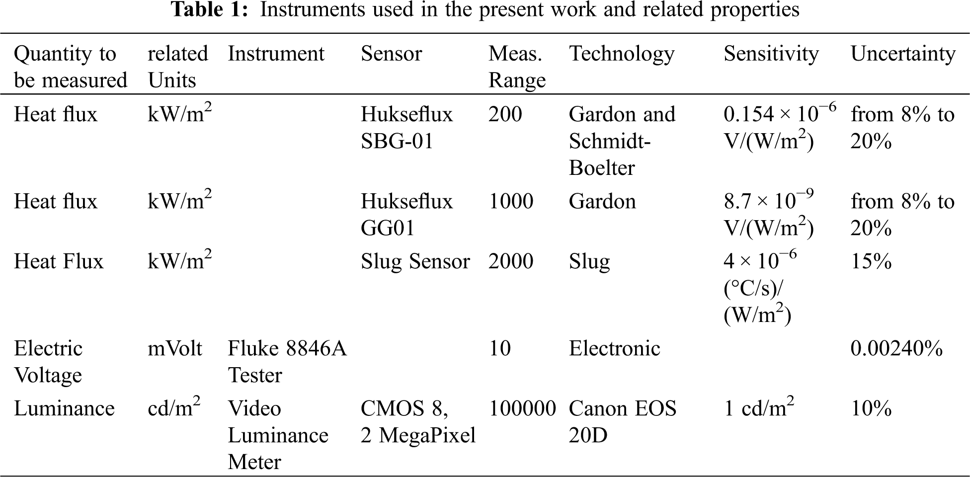
Table 1 provides relevant information about the all the instruments used in the present work and their accuracy.
2.2 Performances (with Reference Sensor SBG01)
Fig. 2a shows the irradiance curve of the calibration system as the supplied power varies, measured by the reference sensor SBG01 (shown in Fig. 2b). The maximum irradiance reached by the reference sensor is 200 kW/m2, sufficient for the calibration of many sensors used in the industrial and aerospace sectors.
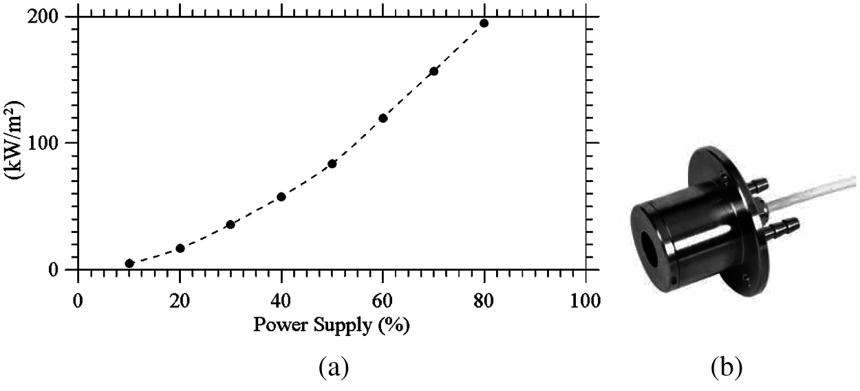
Figure 2: (a): irradiance curve; (b): reference sensor SBG01
According to a preliminary study conducted in order to find the optimal hole size in combination with the reference sensor SBG01, it has been found that the irradiance probe (equipped with a sensitive circular element with a radius of 7.3 mm), must be conveniently placed 20 mm from the hole of the aforementioned cylinder (the lamp being located inside the cylinder). The test setup is shown in Figs. 3a and 3b.

Figure 3: (a): the cylinder around the lamp; (b): test setup
Additionally, considering that the thermal radiation from the filament of the lamp propagates through the cylinder in the same way as the visible radiation, a dedicated photometric analysis of the lamp-cylinder system has been conducted to evaluate the incident flux on the sensitive part of the calibration sensor. The gonio-photometric study of the lamp-cylinder system has been based on the criteria of the typical photometric characterization of a lighting fixture and has been conducted in the framework of a consolidated technique, which relies on a video-luminance-meter (see Table 1) and a luminance-mapping approach to obtain the luminous flux through some geometrical calculations (Bellia et al. [13]). In particular three different configurations have been characterized, with the hole diameter made on the cylinder of 4, 8 and 12 mm (Fig. 4). The resulting photometric solid is that of a source with a beam aperture of less than 10° in the case of the 4 mm hole and approximately 20° for the 8 and 12 mm holes.
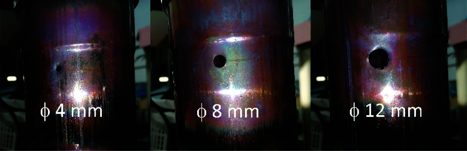
Figure 4: Cylinders with different holes
The photometric curves of three configurations are shown in Fig. 5; they represent the trend of the light intensity in candles (cd) for a lamp power of 1,000 W, equal to 20% of the maximum achievable power. Since these are roto-symmetrical sources, a single curve for each configuration is representative of all planes from C 0–180 to C 90–270.
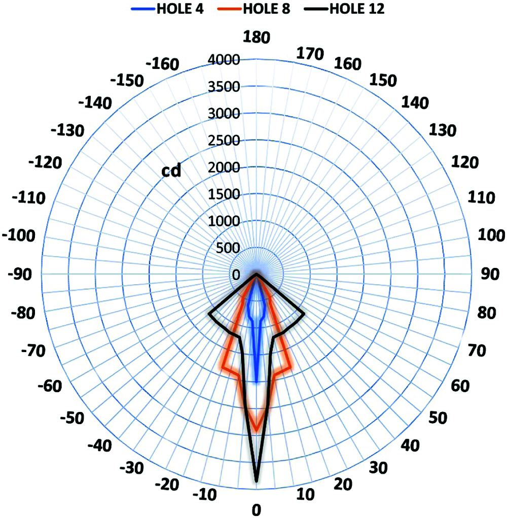
Figure 5: Photometric curves for the three holes
For all the considered cases a central peak exists with a very narrow emission angle and a widening of the beam which, in the case of the configuration with the 4 mm hole, is minimal, while for the configuration with the 8 mm hole it widens up to 20° and for the 12 mm hole it extends up to 50°. What differentiates the configurations with 8 mm hole and 12 mm hole the most is the different flux distribution.
By virtue of photometric measurements we have calculated the incident luminous flux on the sensor for the three studied configurations. The sensor area has been divided into four sectors with an angular pitch of 5° (as illustrated in Fig. 6). For each sector, the solid angle with respect to the point of emission of the concentrator and the average value of the light intensity have been calculated.
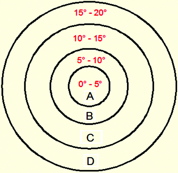
Figure 6: Sectors divisions
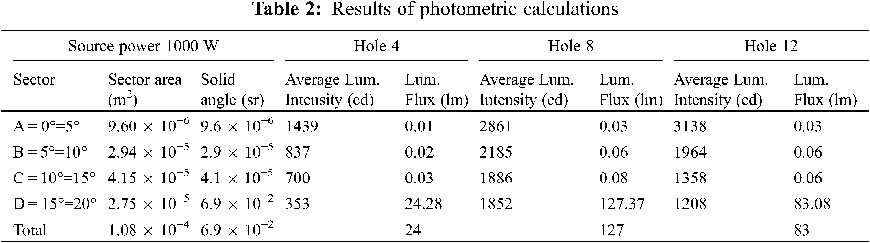
As witnessed by Table 2, where the outcomes of such calculations have been quantitatively substantiated, the maximum value of luminous flux concentrated on the sensitive area of the sensor is obtained with the 8 mm hole, while the flows relating to the 12 mm hole and 4 mm hole are lower. An explanation for this trend can be elaborated in its simplest form taking into account the different geometric emission characteristics of the three configurations and how this geometry is interfaced with the sensitive surface of the sensor.
Along these lines, by inspection of Fig. 7, the reader will immediately realize that the configuration with the 8 mm hole is the best possible among the three considered cases. Notably, with this configuration, at 80% of the lamp power supply, it is possible to obtain an irradiance of 400 kW/m2, which is doubled with respect to the irradiance obtained without concentrator. The plot also shows the values above 80% of the power supply, obtained by extrapolation.
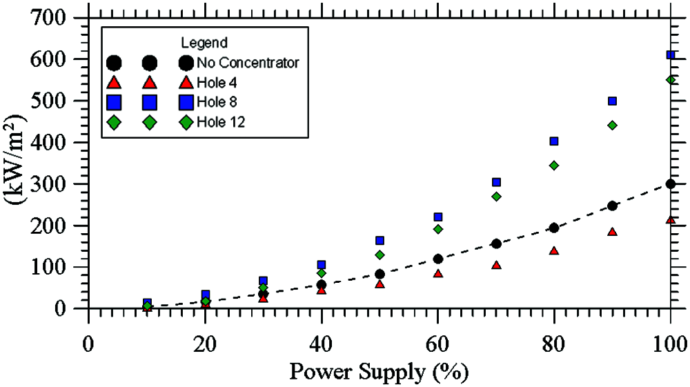
Figure 7: Irradiance curves for the three holes (the spline is used to guide the eye)
3 Upgrading the Calibration System
In order to extend the calibration range (towards the end to expand the set of thermal probes that can be calibrated using the proposed approach, as explained in the introduction), a new reference sensor and a second heat flux source have been added to the original setup, as illustrated in detail in the following two subsections.
The additional sensor (Fig. 8) covers the heat flux range between 200 and 1000 kW/m2; it is a water-cooled Gardon Gauge sensor (Hukseflux GG01, sensing area dia 4.3 mm, sensitivity 8.7 × 10⁻⁹ V/(W/m2), hereafter, for the sake of brevity simply referred to as “GG01”.
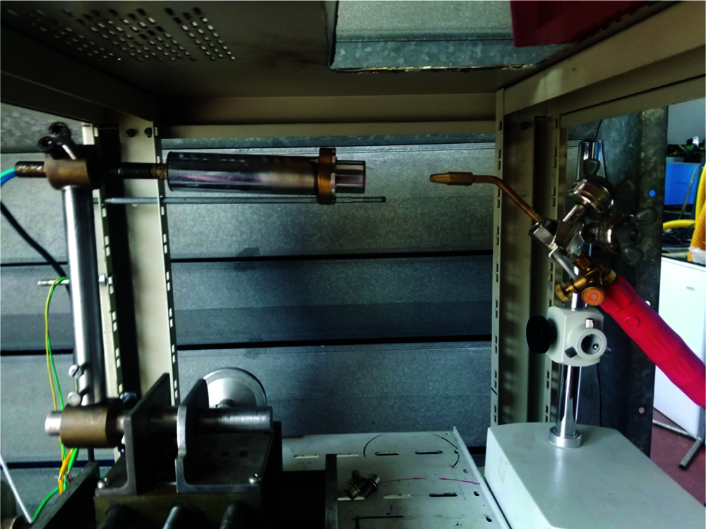
Figure 8: Oxyacetylene torch for convective-radiative heat flux–side view
In addition to the aforementioned pure radiative source (the halogen lamp shown in Fig. 1), a small oxyacetylene torch has been used (OxyTurbo-TurboSet 200 model) as second source able to generate intense convective-radiative heat fluxes, see Fig. 8.
The small oxyacetylene torch is able to reach a maximum temperature of 3100 (°C) with a total flow rate of 0.16 m3/h; the sensor to be used in conjunction with it has been mounted on a precision mechanism, by which it can be progressively displaced along the flame axis, thereby allowing a variation in the experienced heat flux.
The use of oxyacetylene flames to obtain very high heat flux has already been attempted in the past; only recently, however, some experimental results have appeared where their performances could be characterized with an acceptable level of accuracy [14,15].
The outcomes of the present investigation are shown in Fig. 9. With regard to these, we wish to highlight that a ‘correction’ has been applied to such measures (obtained using the aforementioned reference sensors GG01) following the theoretical-numerical arguments elaborated by Fu et al. [15]. As sensor characteristic parameters to be used as an input for the application of such corrections, we have estimated d = 0.2 mm, R = 2.15 mm, and a heat sink temperature of T0 = 30°C. Moreover, the standard measurement sensitivity for heat flux in radiation has been evaluated using the theoretical analysis of Gardon [16] as Lr = 0.0116 mV/(kW/m2). The temperature, Tinf of the gases flowing over the foil surface has been assumed to be 3000 K with the convective heat-transfer coefficient varying in the range between 1000 and 3000 W/(m2K) depending on the considered (convective) case. Accordingly, we have found the relative error on the measured heat flux to span the interval 6–16%.
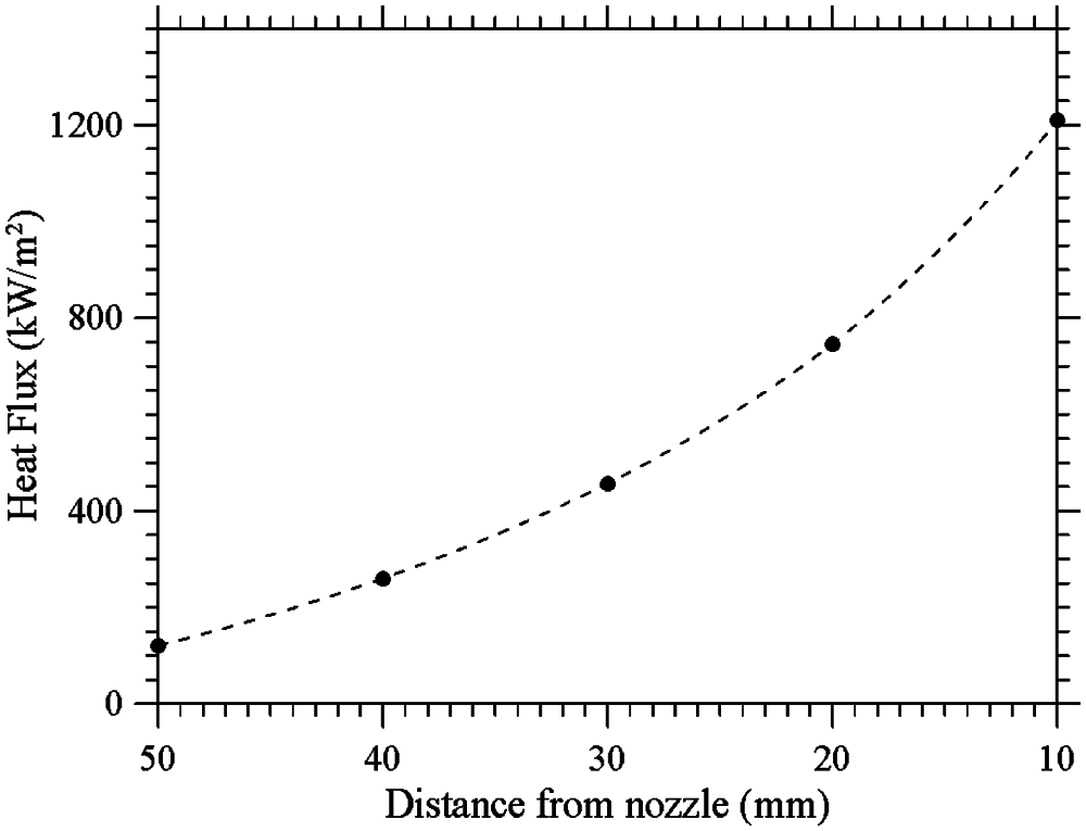
Figure 9: Heat flux vs. nozzle distance for oxyacetylene torch (the spline is used to guide the eye)
4 Use of the Calibration System and Verification of the Calibration Approach
4.1 The Small Planetary Entry Simulator (SPES)
The Small Planetary Entry Simulator (SPES), Fig. 10a, is a high enthalpy supersonic flow facility. It has enjoyed a widespread use over the last 30 years for the simulation of various planetary re-entry conditions ([17–21]).

Figure 10: Small planetary entry simulator (SPES): (a) overall picture, (b) layout
As shown in Fig. 10b, it pertains to the general category of continuous, open circuit arc-driven facilities. It consists of:
1. A gas feeding system able to support mass flow rates in the range from 0.5 to 1 g/s and even beyond
2. An electric arc-heater (industrial plasma torch, Sulzer-MetCo 9MB-M, with arc swirl stabilization), operating with pure inert gases (normally Nitrogen but also Argon, Helium, Hydrogen and their mixtures can be used) at maximum power of 60 kW
3. A mixing chamber (swirl mixer) where cold gases (oxygen, carbon dioxide and others) can be added to the hot plasma gas to generate gas mixtures that can mimic different planetary atmospheres.
4. Interchangeable conical nozzles with different areal ratios (4, 20, 56) able to support values of the Mach number from 3 to 6
5. A test chamber with cylindrical shape
6. A diffuser comprising 3 stages or parts
7. A heat exchanger
8. A vacuum system (capable of minimum pressure of 50 Pa in the test chamber)
9. Exhaust (open air, after gas purification)
The ability of this equipment to cope with very high heat fluxes has been already demonstrated in the framework of various experimental campaigns. In fact, the heat flux that is generated at the stagnation point of suitably shaped bodies (Fig. 11a) can be measured accurately (Esposito et al. [22,23]). Such shapes are used to mimic the part of the spacecraft most exposed to the extreme aero-thermodynamic conditions, which occur during the reentry (Fig. 11b). As an example, Fig. 11c shows the heat flux at the stagnation point of the probe shown in Fig. 11b as a function of the flow total enthalpy Hcl, for a pure Nitrogen flow (where the subscript “fc” and “nc” stand for fully catalytic and non-catalytic wall, respectively).

Figure 11: (a) Heat flux probe, (b) the probe during a test run in SPES, (c) heat flux at the probe stagnation point measured during the test (the subscripts “fc” and “nc” stand for fully catalytic and non-catalytic wall, respectively; the spline curves are used to guide the eye)
Different types of sensors/transducers have been used for these measurements, including the Gardon Gauge (Gardon [16]), the Schmidt-Boelter Gauge (Kidd et al. [24]) and the Slug Calorimeter (ASTM E457–08 [25]).
4.2 Calibration of Slug Sensors for SPES
With a new heat source in place and related procedure (as illustrated in Section 3.2) to correct the readings of the new GG01 reference sensor to account for convective contributions, we have implemented a hybrid approach based on the combined use of the two heat sources (i.e., the purely radiative halogen lamp and the convective-radiative oxyacetylene torch), thereby extending the range of measurable heat fluxes to the maximum value allowed by the reference sensor (namely 1000 kW/m2). In particular, in order to demonstrate the feasibility and reliability of the proposed approach, we have applied it for the calibration of a Tungsten Slug Calorimeter mounted in a spherical probe and used in SPES (named “W1”in the following).
In Fig. 12, the outcomes of such attempt are reported in terms of the heat flux resulting from the use of Halogen Lamp and Oxyacetylene Flame, merged on a single interpolation line in the range of the GG01 sensor (up to 1000 kW/m2 approximately). The good quantitative and qualitative agreement of the two branches in a certain neighborhood of point corresponding to heat flux 200 kW/m2, somehow witnesses the consistency and accuracy of the overall approach.
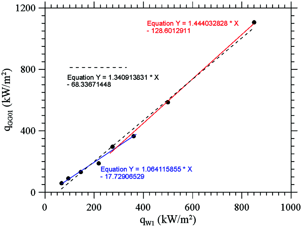
Figure 12: “hybrid” calibration in the range of the GG01 sensor
Along the same lines, Figs. 13 and 14 quantitatively illustrate the relationship between the power supplied and the heat flux in the frame of the pure radiation and hybrid calibration approach, respectively. As the reader will realize by inspecting Fig. 12, the lamp-based calibration can be extended up to 500 kW/m2 about.
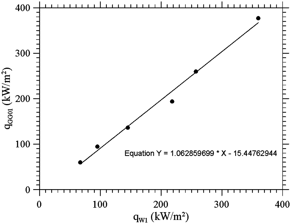
Figure 13: Slug W1 calibration–pure radiative source
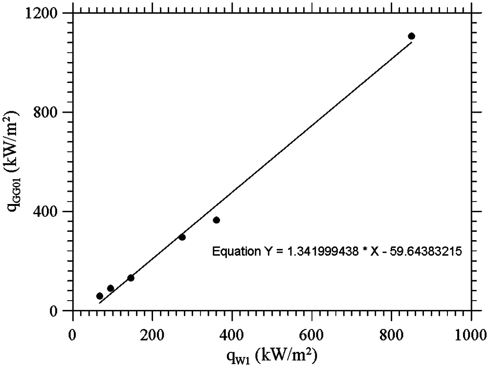
Figure 14: Slug W1 calibration–hybrid approach
In particular, the following Test-Case has been considered to assess/validate the calibration Procedure in the frame of the hybrid approach (see Table 3).
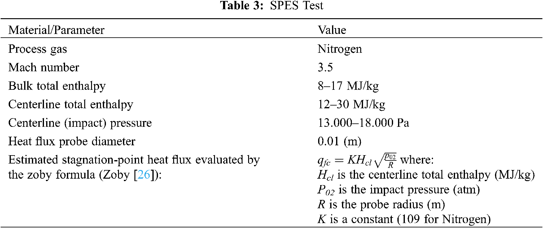
Note that Tungsten surface of the Slug Sensor can be considered non-catalytic (nc). The outcomes of these tests are finally shown in Fig. 15, where the “qnc” values (square symbols) are calculated by the Zoby formula reported in Table 3 and qW−exp are measured values (triangular symbols).
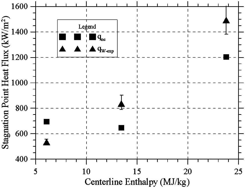
Figure 15: Slug sensor calibration–SPES Test [the “qnc” values (square symbols) are calculated by the Zoby formula reported in Table 3, while qW−exp are measured values (triangular symbols)]
In the past, procedures based on the calculation of the luminous flux impinging on the sensitive surface of a thermal probe have proved to be a viable method for the setup of many calibration facilities. In the present work, evidence has been provided that, starting from a reliable approach based on the well-known possibility to characterize a radiative heat flux according to established standards, extension of the maximum heat flux to values typical of the hypersonic regime is feasible if well-characterized ‘convective’ (eventually convective-radiative) flux sources are introduced in the considered process. The effective implementation of such a hybrid strategy has required cross-validation through the use of independent reference sensors and meaningful consideration of earlier information available in the literature for the characterization of convective heat sources.
The overall approach has been implemented using a Hukseflux SBG01 water-cooled sensor with Gardon and Schmidt-Boelter technology, 200 kW/m2 measurement range, sensing area dia. 10 mm and sensitivity 0.154 × 10⁻⁶ V/(W/m2), a water-cooled Gardon Gauge sensor (Hukseflux GG01, sensing area dia 4.3 mm, sensitivity 8.7 × 10⁻⁹ V/(W/m2), an OSRAM 64805 5000 W–240 V halogen lamp for professional cinema and television use (with a rated luminous flux of 135,000 lm, luminous efficiency of 27 lm/W and a color temperature of 3200 K) and a small oxyacetylene torch (OxyTurbo -TurboSet 200 model) able to reach a maximum temperature of 3100 (°C) with a total flow rate of 0.16 m3/h.
Verification/validation of such a strategy has been achieved using a high enthalpy supersonic flow facility relying on an electric arc-heater (industrial plasma torch, Sulzer-MetCo 9MB-M with arc swirl stabilization), through dedicates tests at Mach Number 3.5 and bulk total enthalpy in the range 8–17 MJ/kg with pure Nitrogen as work gas.
Given the consistency and accuracy displayed by the obtained data, the present efforts somehow demonstrate that, although attempts of such a king are still almost completely absent in the literature, the combined use of radiative and convective heat sources should be regarded as a viable strategy to achieve the very high heat fluxes that typically occur during the hypersonic re-entry phase of space vehicles.
Funding Statement: The authors received no specific funding for this study.
Conflicts of Interest: The authors declare that they have no conflicts of interest to report regarding the present study.
1. Zare-Behtash, H., Lo, K. H., Yang, L., Kontis, K. (2016). Pressure sensitive paint measurements at high mach numbers. Flow Measurement and Instrumentation, 52, 10–16. DOI 10.1016/j.flowmeasinst.2016.02.004. [Google Scholar] [CrossRef]
2. Wang, J., Han, F., Lei, L., Lee, C. (2020). Numerical study of high-temperature nonequilibrium flow around reentry vehicle coupled with thermal radiation. Fluid Dynamics & Materials Processing, 16(3), 601–613. DOI 10.32604/fdmp.2020.09624. [Google Scholar] [CrossRef]
3. Zhou, Y., Ju, P. (2020). Effects of wall emissivity on aerodynamic heating in scramjets. Fluid Dynamics & Materials Processing, 16(6), 1273–1283. DOI 10.32604/fdmp.2020.09666. [Google Scholar] [CrossRef]
4. Pullins, C. A., Diller, T. E. (2010). In situ high temperature heat flux sensor calibration. International Journal of Heat Mass Transfer, 53(17–18), 3429–3438. DOI 10.1016/j.ijheatmasstransfer.2010.03.042. [Google Scholar] [CrossRef]
5. Vadivel, M., Bhalaji, G. R., Raam, C. (2016). Experimental calibration of heat flux from copper slug calorimeter in high speed combustor. International Journal of Modern Engineering Research, 6(12), 12–16. [Google Scholar]
6. Barber, J. A. (1965). Comparison of heat-flux sensors using thermal radiation sources, radiant heat division environmental research and operations department. Sandia Corporation, Albuquerque, New Mexico, USA. SC-DC-651507. [Google Scholar]
7. Diller, T. E. (1993). Advances in heat flux measurements. Advances Heat Transfer, 23, 279–368. DOI 10.1016/S0065‐2717(08)70008‐X. [Google Scholar] [CrossRef]
8. Hager, J. M., Onishi, S., Langley, L. W., Diller, T. E. (1993). High temperature heat flux measurements. AIAA Journal of Thermophysics, 7, 531–534. DOI 10.2514/6.1991‐165. [Google Scholar] [CrossRef]
9. Murthy, A. V., Tsai, B. K., Gibson, C. E., (1997). Calibration of high heat flux sensors at NIS. Journal of Research of the National Institute of Standards and Technology, 102(4), 479–488. DOI 10.6028/jres.102.032. [Google Scholar] [CrossRef]
10. Hunter, E., Walker, J. (1992). Calibration of an electrically calibrated radiometer and two heat flux transducers to be used in the FAA flammabilty testing program, internal memorandum, radiometric physics division. National Institute of Standards and Technology, Gaithersburg, MD. [Google Scholar]
11. Olsson, S. (1989). Calibration of thermal radiometers-the development of a new method. SP Report 1989:04, Nordtest Project 640–86, Part 1. Swedish National Testing and Research Institute, Sweden. [Google Scholar]
12. Pitts, W. M., Murthy, A. V., de Ris, J. L., Filtz, J., Nygard, K. et al. (2006). Round robin study of total heat flux gauge calibration at fire laboratories. Fire Safety Journal, 41, 459–475. DOI 10.1016/j.firesaf.2006.04.004. [Google Scholar] [CrossRef]
13. Bellia, L., Spada, G. (2014). Photometric characterization of small sources with high dynamic range illuminance mapping. Lighting Research and Technology, 46, 329–340. DOI 10.1177/1477153513476511. [Google Scholar] [CrossRef]
14. Paul, A., Binner, J. G. P., Vaidhyanathan, B., Heaton, A. C. J., Brown, P. M. (2016). Heat flux mapping of oxyacetylene flames and their use to characterise Cf-HfB2 composites. Advances in Applied Ceramics, 115(3), 158–165. DOI 10.1080/17436753.2015.1104050. [Google Scholar] [CrossRef]
15. Fu, T., Zong, A., Zhang, Y., Wang, H. S. (2016). A method to measure heat flux in convection using gardon gauge. Applied Thermal Engineering, 108, 1357–1361. DOI 10.1016/j.applthermaleng.2016.07.164. [Google Scholar] [CrossRef]
16. Gardon, R. (1953). An instrument for the direct measurement of intense thermal radiation. Review of Scientific Instruments, 24, 366–370. DOI 10.1063/1.1770712. [Google Scholar] [CrossRef]
17. Esposito, A., Monti, R., Russo, G. P., Savino, R., Ferrigno, F. (1997). Upgrading of an Arc-heated flow facility for re-entry simulation. In: Transactions on modelling and simulation, pp. 491–500. WIT Press, UK. [Google Scholar]
18. Esposito, A., Aponte, F. (2018). Frozen sonic flow applied to Arc-heated facilities for planetary entry simulation, journal of aerospace science. Technology and Systems, 97(3), 153–162. DOI 10.1007/BF03404769. [Google Scholar] [CrossRef]
19. Esposito, A., Lappa, M. (2020). Extension of the frozen sonic flow method to mixtures of polyatomic gases. AIAA Journal, 58(1), 265–277. DOI 10.2514/1.J058472. [Google Scholar] [CrossRef]
20. Esposito, A., Lappa, M., Zuppardi, G., Allouis, C., Apicella, B. et al. (2020). On the formation and accumulation of solid carbon particles in high-enthalpy flows mimicking re-entry in the titan atmosphere. Fluids, 5(2), 93. DOI 10.3390/fluids5020093. [Google Scholar] [CrossRef]
21. Zuppardi, G., Esposito, A. (2001). Blowdown Arc facility for Low- density hypersonic wind-tunnel testing. Journal of Spacecraft and Rockets, 38(6), 946–948. DOI 10.2514/2.3769. [Google Scholar] [CrossRef]
22. Esposito, A., Monti, R., Iannotti, G. (1996). Heat flux measurements in high enthalpy supersonic flows. 6th TEMPMEKO, 96, Turin. [Google Scholar]
23. Esposito, A., de Rosa, F., Caso, V., Parente, F. (2010). Design of slug calorimeters for re-entry tests. International Planetary Probe Workshop, 2010, 14–18. [Google Scholar]
24. Kidd, C. T., Nelson, C. G. (1995). How the schmidt-boelter gage really works. Proceedings of the 41st International Instrumentation Symposium, pp. 347–368. Research Triangle Park, NC: ISA. [Google Scholar]
25. ASTM E457–08 (2015). Standard test method for measuring heat-transfer rate using a thermal capacitance (Slug) calorimeter. https://www.astm.org/Standards/E457.htm. [Google Scholar]
26. Zoby, E. (1968). Empirical stagnation-point heat-transfer relation in several Gas mixtures at high enthalpy levels. NASA TN D-4799. [Google Scholar]
 | This work is licensed under a Creative Commons Attribution 4.0 International License, which permits unrestricted use, distribution, and reproduction in any medium, provided the original work is properly cited. |