| Fluid Dynamics & Materials Processing |
DOI: 10.32604/fdmp.2022.018500
ARTICLE
Optimization of a High-pressure Water-Powder Mixing Prototype for Offshore Platforms
1State Key Laboratory of Oil and Gas Reservoir Geology and Exploitation, Southwest Petroleum University, Chengdu, 610500, China
2School of Petroleum and Natural Gas Engineering, Southwest Petroleum University, Chengdu, 610500, China
3Research Institute of Shaanxi Yanchang Petroleum (Group) Co., Ltd., Xi’an, 710000, China
*Corresponding Author: Shu Zheng. Email: shuzheng66@126.com
Received: 29 July 2021; Accepted: 26 September 2021
Abstract: A new device is designed to promote the mixing of high-pressure water jets and powders in typical industrial applications. The water and powder mixing devices traditionally used on offshore platforms are detrimentally affected by the geometrical configuration of the water nozzle and the powder spraying pipe, which are parallel, resulting in small intersecting volumes of liquid and powder. By allowing the related jets to intersect, in the present work the optimal horizontal distance, vertical distance and intersection angle are determined through a parametric investigation. It is also shown that such values change if the number of water layers is increased from one to two. In such a case, the water and powder intersection volume can be greatly increased because the trajectory of the dry powder particles becomes more chaotic.
Keywords: Polymer; high pressure jet; forced hydration
Polymer flooding technology has been gradually popularized in tertiary recovery industrialization in onshore oilfields, and has achieved good economic and social benefits [1–8]. Since firstly application of polymer flooding in the Bohai Oilfield, offshore polymer flooding has achieved significant results [9–12]. Polymer dissolution process is obviously different from a low-molecular substance, because exists swelling and dissolves process. That is, solvent molecules enter the gaps of the polymer compound and molecular chain curled out, causing the polymer chain could not quickly unfold. Since then, the volume has doubled or even increased by several tens of times offshore platforms [13]. Polymers have a strong affinity with water molecules, and a layer of hydration film is formed around the molecules, which is the main reason for the stability of polymer dissolution effect, also with special groups further influence its solubility. The full contact of polymer dry powder particles with solvent molecules can shorten the dissolution time.
Luo et al. [14] developed a new type of polymer rapid dispersing and dissolving device. The polymer powder was dispersed quickly and powders disappear during the preparation process. Liu et al. [15] used CFD to simulate the jet-type gouache mixer with a 15 mm turbulent nozzle flow state. Pei [16] changed the jet angle of the conventional vertical installation of gouache mixing head, fund that horizontal and vertical mixing occurred in the mixing tank; Shi et al. [17] designed a new type of ZJ30 polymer injection dispersing and dissolving device, which uses a combination of closed-loop control with inverter step less adjustment and pneumatic powder delivering. It has the functions of injection, continuous liquid distribution, continuous injection, and powder and water dispersion; Cui et al. [18] designed a polymer dry powder dispersing and dissolving device. Water was sprayed from the pipeline to the side entrance of the water powder mixer, and formed a vortex at the internal surface, and the entrainment action forms a vacuum to quickly inhale particles; and studied the amount of dry powder to shorten the polymer dissolution time; Wang et al. [19] optimized the rapid-dissolving device and simulate the liquid flow capacity, speed, device structure, etc. Not only can accelerates dissolution, and the stretch greatly shortens the polymer swelling stage.
Nilsson et al. [20–28] have discovered dioxane, tetrahydrofuran, N, N’-dimethylformamide, methanol, formamide could accelerate polymer dissolve, also found that the association structure of the hydrophobic associating polymer solution disappears, and the disappearance of the association structure causes the viscosity of the solution drop sharply. Mahammad et al. [29,30] studied the relationship between cyclodextrin and different hydrophobically modified copolymers, and β-cyclodextrin can be physically adsorbed on the polymer to destroy the association relationship between the hydrophobically modified polies (N-isopropyl acrylamide) copolymer (PNIPAM). The cause of the association failure is due to the hydrophobic group and the complex packages between β-CD cavities.
The polymer dispersing and mixing device is the first-node of polymer dissolution. Solvent injection speed, dry powder deliver speed and device structure all have an impact on the polymer dissolution. If the polymer dry powders cannot fully contact with the solvent at this stage, agglomerated Fish-Eyes will be formed. Fish-Eyes enter the polymer dissolution tank and quickly deposited in the tank bottom. As the stirring time increases, the agitator wrapped by Gel-like polymer, and small clumps cannot be completely dissolved, which eventually causes the polymer solution without being completely dissolved. The efficiency of sweeping and washing oil both drops drastically. The viscosity drops drastically after rapid shearing through the near-wellbore zone, further reduce its performance. By optimize a high-pressure water-powder mixing device, by studying the influence of horizontal distance, vertical height distance, the angle between the two cone axes, the nozzle pressure and the double nozzle interval, the water powder can be fully mixing cannot form Fish-Eyes and accelerate the dissolution of the polymer.
2 High-Pressure Water-Powder Mixing Device
Water-powder mixing device currently used on the offshore platform (Fig. 1), the nozzle is parallel to the powder spraying pipe. The sprayed high pressure of water and dry powder particles cannot be fully mixed. There are two main reasons. On the one hand, due to the parallel state of the hydration head and the powder spraying pipe, the intersecting volume of water and dry powder particles is small; on the other hand, part of the polymer dry powder particles directly enter the mixing tank without contacting water. Therefore, the water-powder mixing device has a relatively large defect for sufficient water-powder dispersion and mixing.
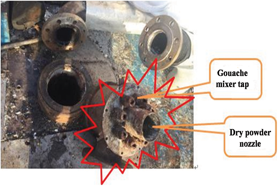
Figure 1: Schematic diagram of offshore water-powder mixer
Combined with the on-site production situation of the offshore platform, a plan diagram of the high-pressure jet dispersion mixing and forced hydration device was designed (Fig. 2). The device is mainly composed of a hydration head, a dry powder nozzle, a hydration head mounting ring, and a hydration head joint. Under the air supply device, the polymer dry powder particles are sprayed through powder nozzle and mixed with the high-pressure water sprayed from the hydration head.
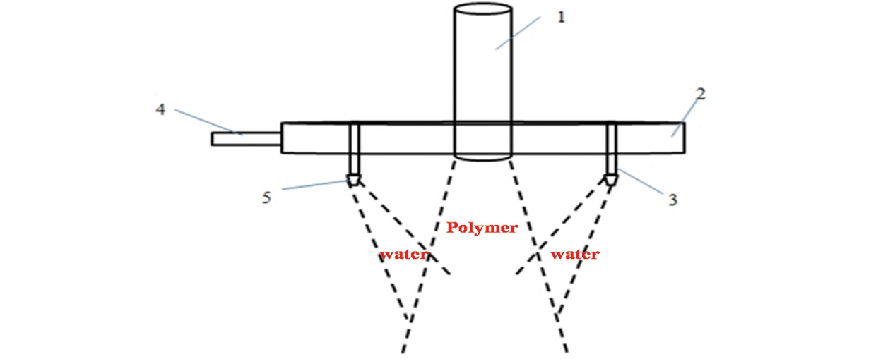
Figure 2: Schematic plan view of the high-pressure water-powder mixing device 1—Dry powder nozzle; 2—High pressure hydration head mounting ring; 3—High pressure hydration head joint; 4—Water source inlet; 5—Conical tap with cylindrical section
The high-pressure water-powder mixing device is researched on the basis of the non-submerged jet flow, and the intersecting volume of the high-pressure water and the polymer dry powder, which is a crucial factor affecting the mixing efficiency of the dispersion mixing device.
According to whether the media is the same, the jet is divided into submerged jet and non-submerged jet. There are three different media for polymer dispersion and mixing, obviously, the jets of polymer and water are non-submerged jets. The structure diagram of non-submerged water jet is shown in Fig. 3.
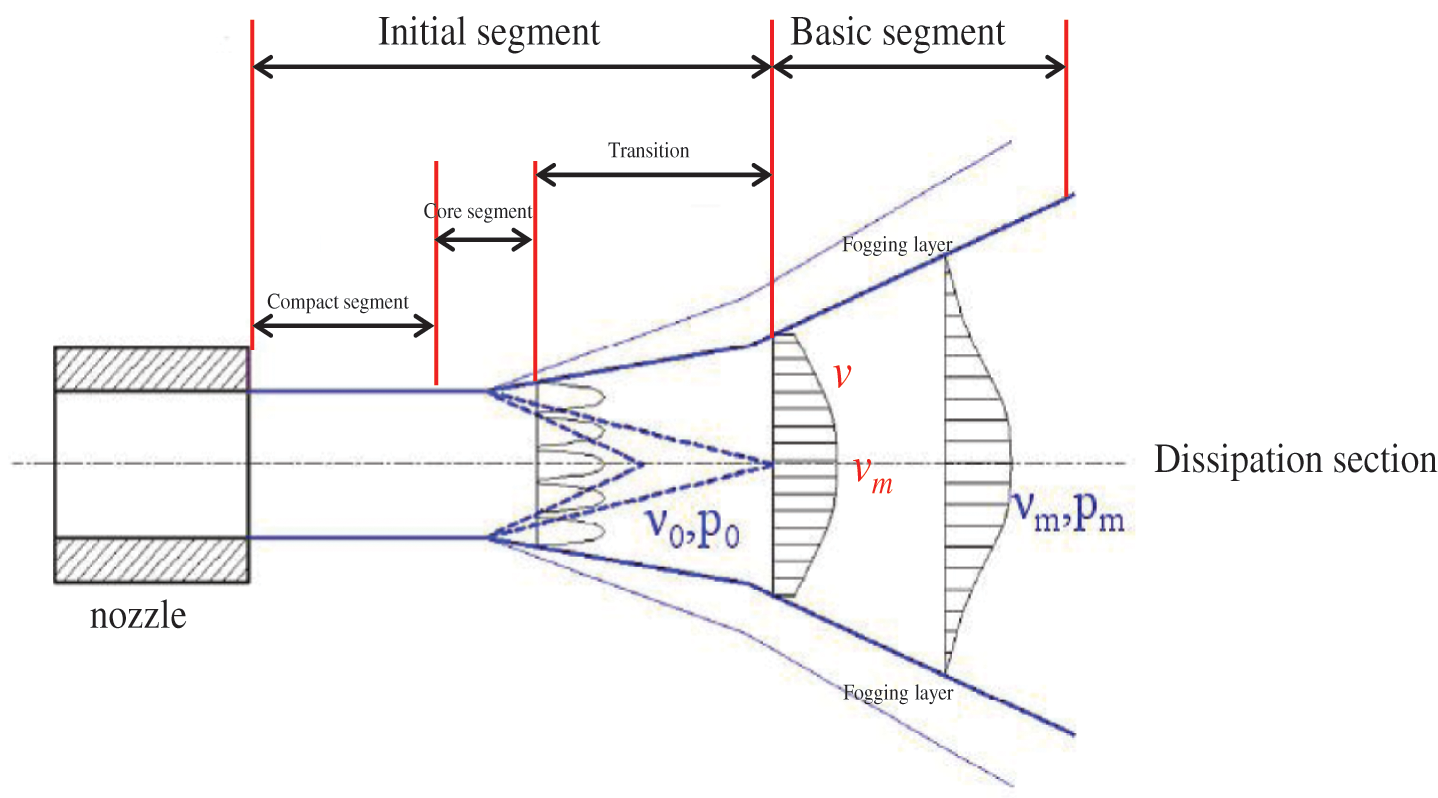
Figure 3: Structural morphology of water jet
The jet has a same velocity in nozzle place, as the distance increases, dry powder particles are mixed into the jet [31,32], which increases the cross-sectional resistance of the jet. Part of the flow in the boundary layer of the jet still maintains the ejection velocity v0 (Core segment). With the increase of the ejection distance in x axis, the boundary layer expands outward and tends to expand outward (Transition), but the speed at the center is still v0. The outer boundary layer expanding, driving more dry powder particles into the boundary layer and the inner boundary layer also expands inside. The erosion of the core area causes the vertical velocity to gradually decrease (Basic segment), at this time, an atomized layer is formed between the inner and outer interfaces. The basic segment of the non-submerged jet is the main area of water and powder mixing. In order to fully mix, the overlap volume of the core area of the nozzle must be maximized, and the atomization layer seen at the internal and external interfaces should be used to maximize the aggregation. So the dry powder can be fully atomized when it meets with water.
The mixing efficiency of polymer dry powder and high-pressure water dispersion, that is, the intersecting volume of the two, is an important parameter that affects the dispersion and mixing. Therefore, it is necessary to discuss the intersecting volume of the two to ensure that the mixing efficiency of dry powder and water is maximized. Supporting mixed volume of water and dry powder sprayed by the nozzle under a single nozzle. Then, according to the principle of maximizing the intersection volume of the cones, a certain number of nozzles are arranged at a certain height of the dry powder injection cone, so that the mixing of water and powder can be maximized under the condition of a certain spray range and spray angle. Calculate the intersecting volume of the dry powder cone and the water cone. The relevant parameters of the mathematical model of the cone shape are shown in Fig. 4.
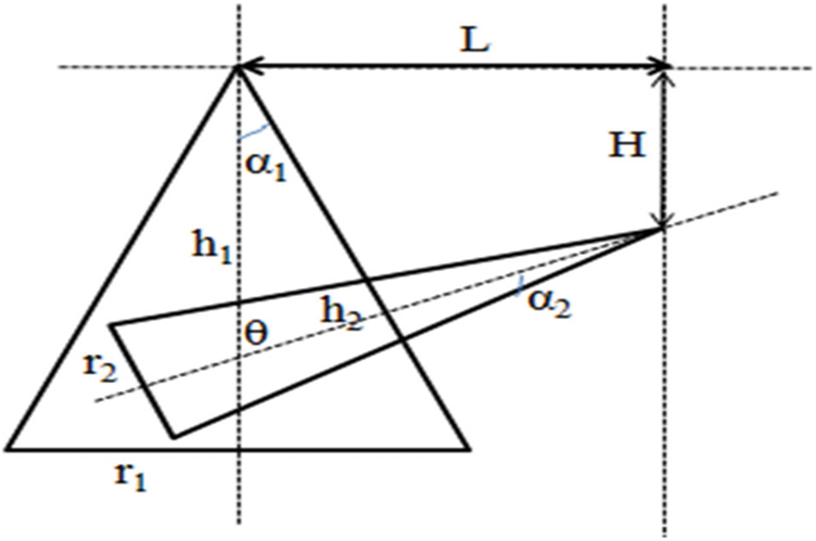
Figure 4: Schematic diagram of the intersection of cones
Among them: α1—Opening polar angle of the dry powder cone;
α2—Opening polar angle of the water jet cone;
h1—Height of the dry powder cone;
h2—Height of the water jet cone;
r1—Radius of the bottom surface of the dry powder cone;
r2—Radius of the bottom surface of the water jet cone;
θ—Included angle between the two cone guidelines;
H—Height difference between the vertices of the two cones;
L—Difference in the horizontal position of the vertices of the two cones.
Control the shape of the cone parameters, such as the polar angle, the radius of the bottom surface, and the height of the cone. The shape of the cone is determined by changing its relative position. The main parameters are the horizontal distance L, the vertical height distance H and the angle between the two cone axes θ. By finding the functional relationship between the volume of the intersection of the two cones and, the parameters L, H, θ are optimized to determine the relative position of the hydration head and the powder spraying pipe.
Other parameters of the high-pressure water-powder mixing device are:
(1) System liquid dispensing speed: 60 m3/h;
(2) Polymer powder feeding pipe diameter: 3in (76.2 mm);
(3) Polymer feeding speed: 500 kg/h;
(4) Air supply Speed: 387.6 m3/h;
(5) Number of dry powder nozzles: 8;
(6) Number of High pressure hydration heads: 1;
(7) The length of the initial section is in accordance with the Leningrad Mining Institute to obtain the calculation formula, the length of the initial section is 69 times the diameter of the jet outlet;
(8) The polar angle of the water jet is 14°, and the polar angle of the jet is 20°.
The cone surface of the dry powder nozzle cone is shown in Fig. 4. The coordinate system is established with the apex of the dry powder cone as the coordinate origin, and the equation of the dry powder cone is:
The water jet cone surface is shown in Fig. 5, assuming that the axis of the water jet cone intersects the z axis at point M (0, 0, −b), and the vertex of the water jet cone is N (x0, y0, z0), then the axis equation for:
Figure 5: Schematic diagram of the cone of dry-powder cone
Figure 7: Schematic diagram of water jet cone alignment
Figure 6: Schematic diagram of the cone of dry-powder cone
The angle between MN and z axis is θ, then:
Suppose the coordinates of point P in the space are (x1, y1, z1), the vertical point of point P on MN is Q (xc, yc, zc), then the equation of NP is:
The equation of MN (Eq. (4)) as a parametric equation, and get:
Point Q is on the straight line MN, then:
The direction vector of
Suppose any point A (x, y, z) on the cone surface, then the angle between the straight line
The equation of axis
From the angle formula of the two straight lines, the cone equation of the water cone can be obtained:
The outlet diameter of the nozzle is the first important parameter selected when designing the nozzle. Under normal circumstances, the size of the nozzle diameter mainly considers the size of the flow and whether the nozzle is forming clog. Apertures increase the flow rate and reduce the risk of clogging; if the aperture is small, the flow rate decreases and the risk of clogging increases. When the intersection angle θ is 0, the horizontal distance L and vertical distance H are shown in Table 1. According to formula (10), the volume of water and powder confluence is calculated, and the calculation result is shown in Fig. 8.
Figure 8: Variation curve of gouache intersection volume with horizontal distance and vertical distance
In the Fig. 8, when the vertical distance is 0, the intersection volume (IV) of gouache and powder is 30.89 × 104 mm2 at a horizontal distance of 50 mm. As the horizontal distance is shortened, IV gradually decreases. When the horizontal distance is 90 mm, IV= 2.31 × 104 mm2, which has been reduced to 7.49% relative to 50 mm. When the horizontal distance is higher than 110 mm, IV is almost close zero. The intersection angle and vertical distance is both equal to zero, nozzles are in a parallel state, resulting in a horizontal distance, it is larger than the diameter of the dry powder nozzle, will be in an invalid confluence state. When the vertical distance is 0, 50, 100, and 150 mm, the IV of gouache is 42.67 × 104 mm2, 55.39 × 104 mm2 and 67.58 × 104 mm2. By changing the vertical distance, the percentage ratio of the IV to L = 50 mm is shown in Table 2. Intersection volume is equal to 67.58 × 104 mm2, when the L = 50 mm, H = 150 mm.
During vertical distance and L = 50 mm, the IV = 42.67 × 104 mm2. The L = 90 mm, the IV is reduced to 13.35%, and when the L = 110 mm, its intersection volume has been reduced to 0.77%. With the gradual increase of the horizontal distance, the volume of the intersection of gouache and powder gradually increases.
Fig. 8 shows that when L = 50 mm and H = 150 mm of the nozzle, the volume of water and powder intersection reaches the maximum. By changing the intersection angle of the nozzles from 0∼40°, the volume of the intersection of water and powder is calculated by formula (10), as shown in Fig. 9.
Figure 9: The change curve of the intersection volume of water and powder with the intersection angle
As shown in Fig. 9, the increase of the angle of intersection, the IV first increases and then decreases. When the angle of intersection is 10°, the volume of the intersection of water and powder is 77.42 × 104 mm2. The angle of intersection is 0, confluence volume increases by 14.57%; intersection angle at 20°, the volume of intersection is 65.90 × 104 mm2, confluence volume decreases 2.49% relatively θ = 0; the angle = 30°, intersection volume is 17.89 × 104 mm2, confluence volume decreases 73.52%; When the angle of intersection increases to 40°, the intersecting volume is reduced to 5.25 × 104 mm2, and there is almost no intersecting volume.
3.2 High Pressure Hydration Head
In addition, considering that the water and powder mixing volume may change when the high pressure hydration head are distributed in two layers, the mixed volume when the high pressure hydration heads are distributed in two layers under the optimal relative position conditions is calculated. The relationship between the pressure of the hydration head and the diameter of the outlet of the hydration head is obtained, and the diameter of the outlet of the hydration head under different pressures is obtained, so as to determine the shape of the water-cone. The shape parameters of the water-cone under different pressures are shown in Table 3.
When the intersecting angle θ = 10°, the horizontal distance L = 50 mm, and the vertical distance H = 150 mm. Calculating the mixed volume of water and powder under different nozzle pressures (Fig. 10).
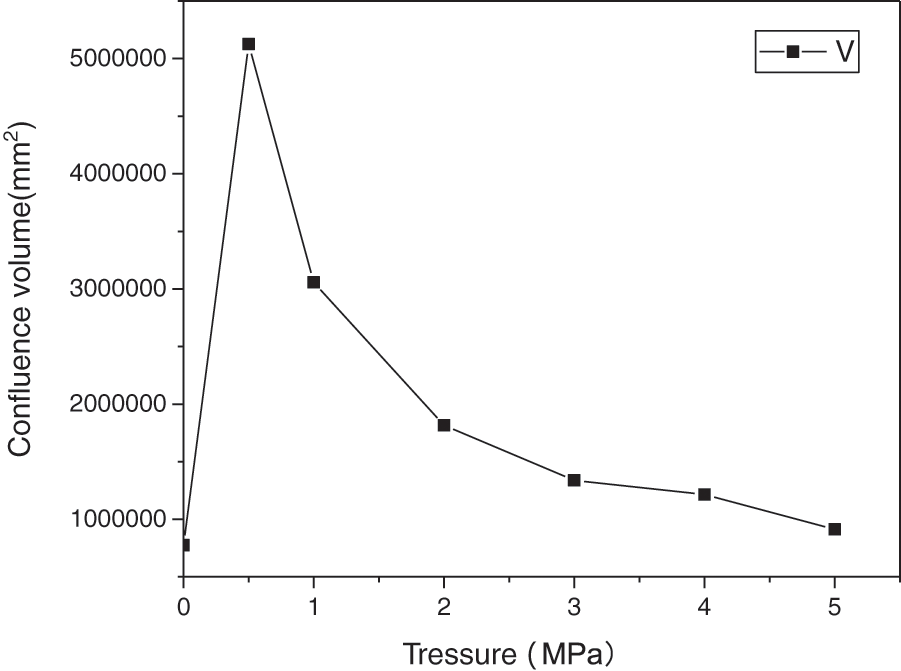
Figure 10: The change curve of the volume of water and powder confluence with the pressure of the nozzle
The increase of nozzle pressure (P), the volume of water and powder intersection gradually decreases in Fig. 10. When the pressure is 0, the mixed volume is 67.58 × 104 mm2. When the pressure rises to 0.5 MPa, the volume of intersection rises to 512.69 × 104 mm2, which is 7.59 times relatively P = 0. When the pressure rises to 1.0 MPa which is 4.52 times of P is 0. It is smaller, but its value is still much larger than that of unpressurized; when the pressure is higher than 3.0 MPa, the intersection volume change smaller, which is about 1.98%, 1.80%, and 1.35% of unpressurized. Therefore, the optimum pressure range of the forced hydration head for high-pressure jet dispersion mixing is 0.5∼2 MPa.
3.3 Double-Layer Hydration Head
A single hydration head has a limited ability to disperse and mix. Double-layer distribution, the mixing volume of water and powder may higher. The interval 50∼250 mm, the isometric side view of different intervals is shown in Fig. 11.
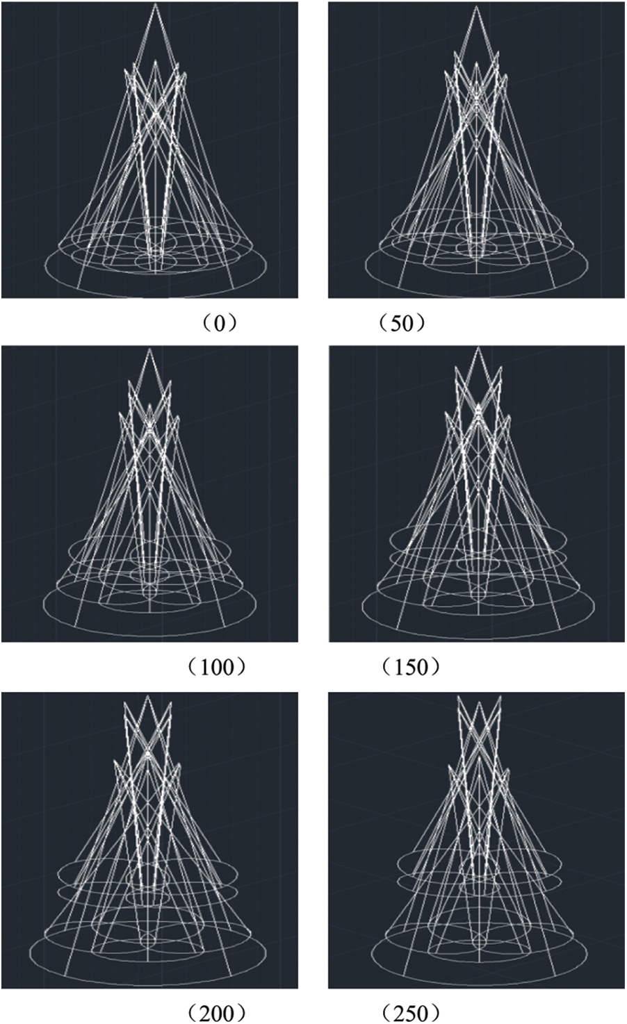
Figure 11: Double-layer distribution isometric side view
According to formula (10), the volume of water and powder confluence is calculated, and the calculation results are shown in Table 4.
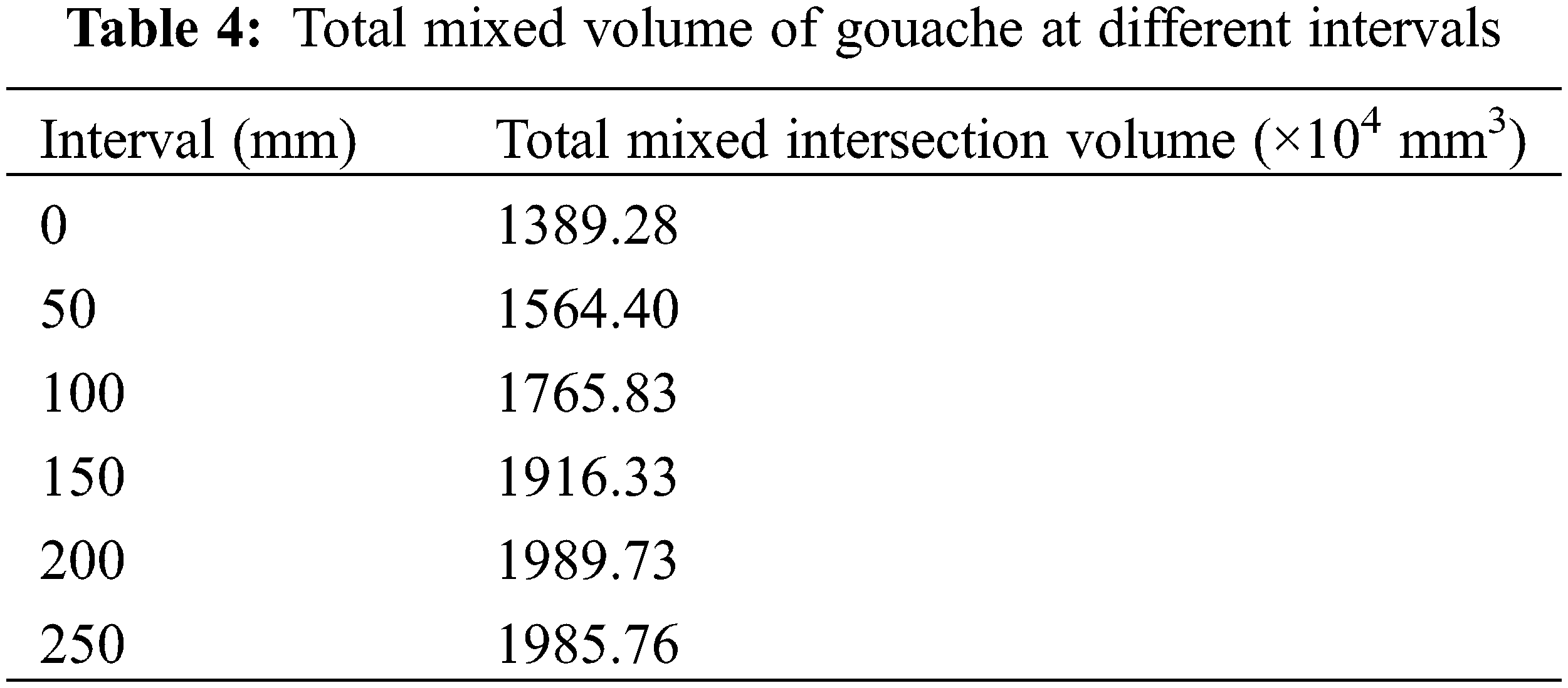
The mixing volume of water and powder in the double-layer distribution of faucets is greater than that in the single-layer distribution in Table 4. As the distance increases, the mixing volume gradually increases and then remains unchanged. When the interval is 200 mm, the total mixing volume of water and powder is the largest, which is 1.43 times of a single layer.
The water and powder mixing device on the offshore platform, the hydration head and the powder injection pipe are in a parallel state and the water and the powder particles intersect with a small volume, which causes the water and the polymer dry powder particles to not be fully mixed. “Fish-eye” agglomerates are prone to appear in the stirring tank, which will increase the dissolve difficulty of the polymer. The mixing device is mainly composed of a hydration head and a dry powder nozzle. A high-pressure water-powder mixing device is designed, by optimizing its parameters and calculating the intersection volume, finally achieves rapid dissolution.
In the case of a single nozzle, the mixed volume of water and dry powder sprayed from the nozzle is calculated. When the horizontal distance is 50 mm, the vertical distance is 150 mm and the intersection angle is 10°, the maximum intersection volume is 77.42 × 104 mm2. By optimize the parameters of the dry powder nozzle and changing the spray pressure of the nozzle, it is concluded that when the pressure is 0.5 MPa, the water powder mixing volume is 7.59 times that of the unpressurized state, and as the pressure gradually rises to 3.0 MPa, the water powder mixing volume is It drops sharply with no change. The center range of the single-layer nozzle is small, the spacing of the faucets is 250 mm of double-layer, and the mixed volume of gouache is 1.43 times that of a single layer.
Acknowledgement: The author thanks the National Science and Technology Major Special Offshore Platform Polymer Rapid Dissolution Technology Research Project for providing funding and data support.
Funding Statement: This work comes from the National Science and Technology Major Special Offshore Platform Polymer Rapid Dissolution Technology Research Project [Grant No. 2016ZX05060].
Conflicts of Interest: The authors declare that they have no conflicts of interest to report regarding the present study.
1. Li, X. N., Zhang, F. S., Liu, G. L. (2021). Review on polymer flooding technology. Conference Series: Earth and Environmental Science, 675, 1755–1370. DOI 10.1088/1755-1315/675/1/012199. [Google Scholar] [CrossRef]
2. Abirov, R., Ivak, H., Nenko, A. P., Abirov, Z., Eremin, N. A. (2019). The associative polymer flooding: An experimental study. Journal of Petroleum Exploration and Production Technology, 1–8. DOI 10.1007/s13202-019-0696-8. [Google Scholar] [CrossRef]
3. Han, D. K., Yang, C. Z., Zhang, Z. Q. (1999). Recent development of enhanced oil recovery in China. Journal of Petroleum Science & Engineering, 22(1), 181–188. DOI 10.1016/S0920-4105(98)00067-9. [Google Scholar] [CrossRef]
4. Flory, P. J. (1953). Principles of polymer chemistry, pp. 125–129. New York: Cornell University Press. [Google Scholar]
5. Mack, J. C., Warren, J. (1984). Performance and operation of a crosslinked polymer flood at sage spring creek unit a natrona county wyoming. Journal of Petroleum Technology, 36(8), 1145–1156. DOI 10.2118/10876-PA. [Google Scholar] [CrossRef]
6. Wang, J., Liu, H. (2014). A novel model and sensitivity analysis for viscoelastic polymer flooding in offshore oilfield. Journal of Industrial and Engineering Chemistry, 20(2), 656–667. DOI 10.1016/j.jiec.2013.05.030. [Google Scholar] [CrossRef]
7. Ding, M., Wang, Y., Han, Y., Liu, Y., Qu, Z. (2020). Experimental investigation of the heterogeneity limit for the application of polymer flooding in reservoirs. Journal of Energy Resources Technology, 143(2), 1–22. DOI 10.1115/1.4047698. [Google Scholar] [CrossRef]
8. Wallqvist, V., Claesson, P. M., Swerin, A., Gane, P., Schoelkopf, J. (2008). Fluid transport in compacted porous talc blocks. Fluid Dynamics & Materials Processing, 4(2), 85–98. DOI 10.3970/fdmp.2008.004.085. [Google Scholar] [CrossRef]
9. Cao, W., Xie, K., Wang, X., Lu, X., Li, X. (2020). Starch graft copolymer and polymer gel applied in bohai oilfield for water plugging and profile control and their mechanisms. Geosystem Engineering, 23(4), 1–8. DOI 10.1080/12269328.2020.1732838. [Google Scholar] [CrossRef]
10. Liu, Z. B., Zhang, W., Ma, K. Q. (2013). Research on residual Oil distribution Law and tapping the potential in horizontal wells in offshore heavy oilfields—By taking XX oilfield in bohai basin for example. Journal of Oil and Gas Technology, 35(5), 115–119. [Google Scholar]
11. He, M. X. (1984). Discussion on development scale and investment of China’s offshore oilfields. ENERGY of CHINA, 3, 14–16. [Google Scholar]
12. Xu, Q. (1994). China’s offshore oil resources. Earth Science, 1, 10–11. [Google Scholar]
13. Cao, B. G., Luo, P. Y., Li, H. B. (2006). Viscoelasticity and rheological behaviors of hydrophobic association polymer solution. Acta Petrolei Sinica, 1, 85–89. DOI 10.3321/j.issn:0253-2697.2006.01.018. [Google Scholar] [CrossRef]
14. Luo, T. T., Lu, Y. P., Pan, Y. M. (2007). Preparation of a new variety of rapid mixing and dissolving equipment of polyacrylamide solution. Mining and Metallurgy, 16(4), 74–76. [Google Scholar]
15. Liu, M., Chen, X. P., Niu, G. F. (2010). Numerical simulation analysis and structural optimization of the jet waterpowder mixer. China Petroleum Machinery, 8, 34–36. [Google Scholar]
16. Pei, Y. (2015). Feasibility analysis of jet mixing in dissolving tank of blower jet dispersing device. Chemical Enterprise Management, 22, 181. [Google Scholar]
17. Shi, Y. Q., Liu, X. F., Yu, X. Z. (1997). ZJ30 polymer injection dispersing and dissolving device. China Petroleum Machinery, 25(12), 27–29. [Google Scholar]
18. Cui, P. Z., Lu, X. C., Jiang, J. (2008). The design and analysis of the polymer dispersion andfusion inject device. Xinjiang Oil & Gas, 4, 92–103. [Google Scholar]
19. Wang, S. K., Shu, Z., Ye, Z. B., Zhu, S. J., Zhang, L. (2021). Simulation and optimization of working parameters of the rapid-dissolution device of hydrophobically associating polymer. AIP Advances, 11(1), 1–8. DOI 10.1063/5.0036883. [Google Scholar] [CrossRef]
20. Nilsson, S., Thuresson, K., Hansson, P., Lindman, B. (1998). Mixed solutions of surfactant and hydrophobically modified polymer. controlling viscosity with micellar size. The Journal of Physical Chemistry B, 102(37), 7099–7105. DOI 10.1021/jp9812379. [Google Scholar] [CrossRef]
21. Wendy, J. C., Philip, D. K., Ferdinand, R. (1985). Effects of molecular weight and plasticization on dissolution rates of thin polymer films. Polymer, 26(7), 1069–1072. DOI 10.1016/0032-3861(85)90230-7. [Google Scholar] [CrossRef]
22. Cram, S. L., Brown, H. R., Spinks, G. M., Hourdet, D., Creton, C. (2005). Hydrophobically modified dimethylacrylamide synthesis and rheological behavior. Macromolecules, 38(7), 2981–2989. DOI 10.1021/ma048504v. [Google Scholar] [CrossRef]
23. Flynn, C. E., Goodwin, J. W. (1991). Association of acrylamide-dodecylmethacrylate copolymers in aqueous solution. 462, 190–206. DOI 10.1021/symposium. [Google Scholar] [CrossRef]
24. Salit, M. S., Jawaid, M., Yusoff, N. B., Hoque, M. E. (2015). Manufacturing of natural fibre-reinforced polymer composites by solvent casting method. Manufacturing of Natural Fibre Reinforced Polymer Composites, 331–349. [Google Scholar]
25. Lacík, I., Candau, F., Selb, J. (1995). Compositional heterogeneity effects in hydrophobically associating water-soluble polymers prepared by micellar copolymerization. Polymer, 36(16), 3197–3211. DOI 10.1016/0032-3861(95)97884-I. [Google Scholar] [CrossRef]
26. Talwar, S., Keith, R. O., Saad, A. K. (2008). Surfactant-mediated modulation of hydrophobic interactions in associative polymer solutions containing cyclodextrin. Langmuir, 25(2), 794–802. DOI 10.1021/la803056e. [Google Scholar] [CrossRef]
27. Vavruch, I. (1965). Kinetics of swelling of dextran gels in solvents. Kolloid-Zeitschrift und Zeitschrift Für Polymere, 205(1), 32–39. [Google Scholar]
28. Li, L., Guo, X., Fu, L., Prud’Homme, R. K., Lincoln, S. F. (2008). Complexation behavior of alpha-, beta-, and gamma-cyclodextrin in modulating and constructing polymer networks. Langmuir the ACS Journal of Surfaces & Colloids, 24(15), 8290–8296. DOI 10.1021/la800859w. [Google Scholar] [CrossRef]
29. Mahammad, S., bdala, A. A., Roberts, G. W., Khan, S. A. (2010). Manipulation of hydrophobic interactions in associative polymers using cyclodextrin and enzyme. Soft Matter, 6(17), 4237–4245. DOI 10.1039/c0sm00054j. [Google Scholar] [CrossRef]
30. Xi, L., Zheng, S., Luo, P., Ye, Z. (2018). Associating polymer networks based on cyclodextrin inclusion compounds for heavy oil recovery. Journal of Chemistry, 2018(2–81–9. [Google Scholar]
31. Muhamad, H., Upreti, S., Lohi, A., Doan, H. (2016). Experimental study of interfacial phenomena between the heavy oil and maximum solvent concentration as function of injection pressures. Fluid Dynamics & Materials Processing, 12(3), 111–123. DOI 10.3970/fdmp.2016.012.111. [Google Scholar] [CrossRef]
32. Liu, M., Zhang, X. K., Wang, D. (2021). Experimental study on the flow characteristics of a plate with a mechanically choked orifice. Fluid Dynamics & Materials Processing, 17(1), 97–107. DOI 10.32604/fdmp.2021.011292. [Google Scholar] [CrossRef]
 | This work is licensed under a Creative Commons Attribution 4.0 International License, which permits unrestricted use, distribution, and reproduction in any medium, provided the original work is properly cited. |