| Fluid Dynamics & Materials Processing |
DOI: 10.32604/fdmp.2022.019139
ARTICLE
Oil Production Optimization by Means of a Combined “Plugging, Profile Control, and Flooding” Treatment: Analysis of Results Obtained Using Computer Tomography and Nuclear Magnetic Resonance
1Cnooc (China) Co., Ltd., Tianjin Branch, Tianjin, 300452, China
2School of Petroleum Engineering, Northeast Petroleum University, Daqing, 163318, China
*Corresponding Author: Wenbo Bao. Email: baowb2@cnooc.com.cn
Received: 05 September 2021; Accepted: 18 December 2021
Abstract: Due to long-term water injection, often oilfields enter the so-called medium and high water cut stage, and it is difficult to achieve good oil recovery and water reduction through standard methods (single profile control and flooding measures). Therefore, in this study, a novel method based on “plugging, profile control, and flooding” being implemented at the same time is proposed. To assess the performances of this approach, physical simulations, computer tomography, and nuclear magnetic resonance are used. The results show that the combination of a gel plugging agent, a polymer microsphere flooding agent, and a high-efficiency oil displacement agent leads to better results in terms of oil recovery with respect to the situation in which these approaches are used separately (the oil recovery is increased by 15.37%). Computer tomography scan results show that with the combined approach, a larger sweep volume and higher oil washing efficiency are obtained. The remaining oil in the cluster form can be recovered in the middle and low permeability layer, increasing the proportion of the columnar and blind end states of the oil. The nuclear magnetic resonance test results show that the combined “plugging, profile control, and flooding” treatment can also be used to control more effectively the dominant channels of the high permeability layer and further expand the recovery degree of the remaining oil in the pores of different sizes in the middle and low permeability layers. However, for the low permeability layer (permeability difference of 20), the benefits in terms of oil recovery are limited.
Keywords: “Plugging, profile control and flooding” measures; computed tomography scan; nuclear magnetic resonance; remaining oil; recovery ratio
The A oilfield is a conventional heavy oil reservoir (in the oil layer, the viscosity of the crude oil is more than 50 mPa·s and the density is more than 0.92 kg/m3) with abundant reserves. It mainly consists of four sets of oil-bearing strata of the Neogene Minghuazhen and Guantao Formations and the Paleogene Dongying and Shahejie Formations. The sedimentary facies of the oil-containing strata are mainly fluvial facies and delta facies. In recent years, there has been a continuous deepening of the water flooding activity. This, coupled with the characteristics of high average permeability, strong heterogeneity, high oil viscosity, and the formation of dominant water flow channels has further aggravated the deterioration of the reservoir’s heterogeneity, resulting in the inefficient and ineffective circulation of the injected water and increasing the water content [1–6].
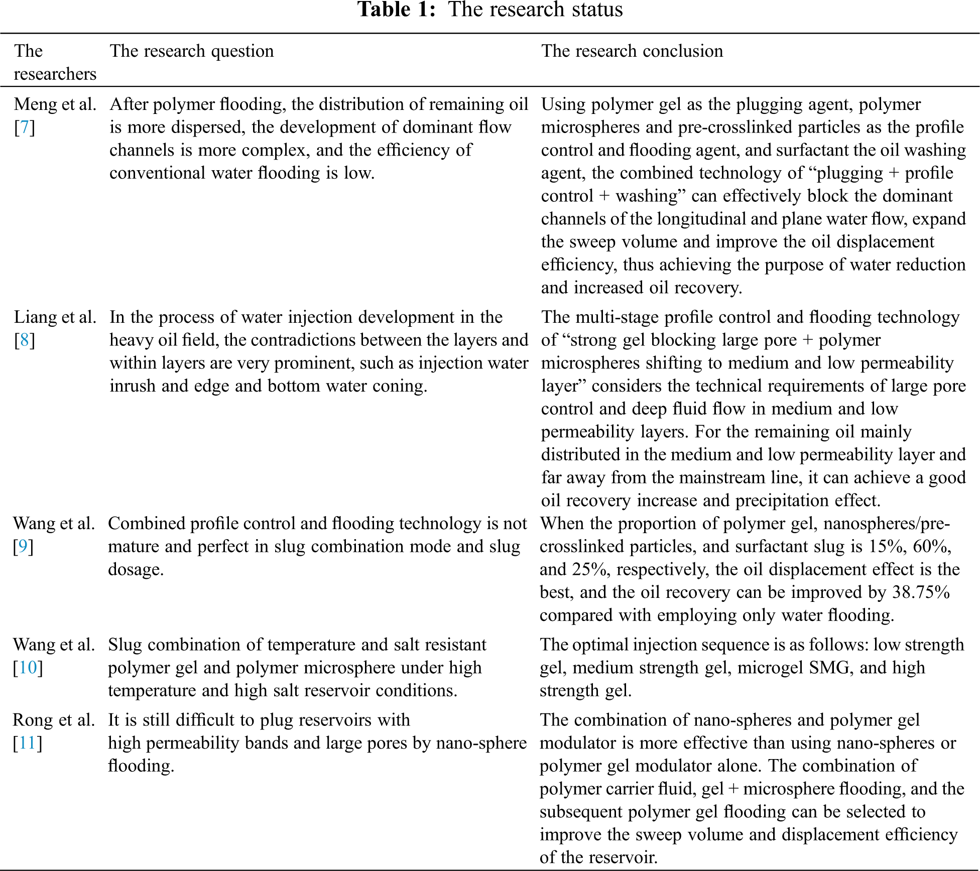
To solve the above problems and improve the efficiency of water flooding, researchers have proposed a variety of treatment options. The research status is shown in Table 1. Meng et al. [7] researched the multi-stage combination technology of plugging, adjusting, and washing after polymer flooding. The results showed that the multi-stage combination system using polymer gel as the plugging agent, pre-crosslinked particles as the regulating and flooding agent, and a high-efficiency oil displacement agent as the washing agent had a better EOR effect than using a single plugging slug [7]. Liang et al. [8] studied the effect of deep profile control and flooding by a multistage combination. The results showed that the multi-stage profile control and flooding technology of “polymer gel profile plugging + polymer microsphere profile control and flooding” could achieve a good oil increase effect by taking into account the technical requirements of large pore control and deep fluid flow in medium and low permeability layers. Wang et al. [9] studied the slug combination and slug dosage of polymer gels, microsphere/pre-crosslinked particles, and surfactant by using a sand filling physical model. The results show that the combined slug injection method is better than the single slug injection method, and that the oil displacement effect is best when the proportion of the slug dosage is 15%, 60%, and 25% [9]. Wang et al. [10] carried out a study on the slug injection sequence using a combined modulated flooding technology and showed that the injection sequence of low strength gel, medium strength gel, polymer microspheres, and high strength gel resulted in the best oil increase effect. Rong et al. [11] studied the oil displacement effect with different combinations of displacement agents. The results show that the combination of nano-spheres, polymer gel control, and a displacement agent has a more significant oil displacement effect than the single use of nano-spheres or polymer gel control or displacement agent, and that the combination of polymer carrying fluid, gel + microspheres, and the subsequent polymer gel control and displacement technology can improve the overall sweep volume and displacement efficiency of reservoirs [11].
Through a large number of experimental studies, oilfield workers have preliminarily explored the treatment idea of profile control and flooding of heterogeneous reservoirs with high permeability bands. High-strength plugging systems such as gels have been used as the pre-plugging slug to improve the reservoir suction profile, and then pre-crosslinked particles or polymer microspheres have been used to improve the medium-high permeability sweep volume. Finally, a surfactant such as a high-efficiency oil displacement agent has been used to improve the oil washing efficiency in the subsequent water flooding process. Although the above treatment method has achieved a good oil recovery increasing effect in laboratory tests, the micro mobilization degree of the remaining oil in each heterogeneous small layer is still not understood, and the micro action mechanism of this method is not clear.
To understand the mechanism of “plugging, profile control, and flooding” treatment, this paper takes the A oilfield as the research object and uses physical simulation experiments to study the oil recovery increase and precipitation effect of using a gel plugging agent, polymer microsphere control, and a high-efficiency displacement agent and their combination. The type and distribution of the remaining oil are quantitatively analyzed using computed tomography (CT) and nuclear magnetic resonance (NMR). Based on the test results, the idea of optimizing plugging control and flooding is further proposed. This idea and method are of great significance to the application and adjustment of profile control and flooding technology in the field.
The experimental agents include a gel plugging agent, a polymer microsphere control agent, and a high-efficiency oil displacement agent. The gel plugging agent is a composite gel system composed of inorganic aluminum gel and polyacrylamide. The polymer microspheres are mainly composed of nano micron polymer microspheres. The main component of the high-efficiency oil displacement agent is an emulsifying viscosity-reducing surface activator.
The experimental oil was mixed with kerosene and degassed crude oil in proportion, and the viscosity was 75.0 mPa·s at a reservoir temperature of 65°C.
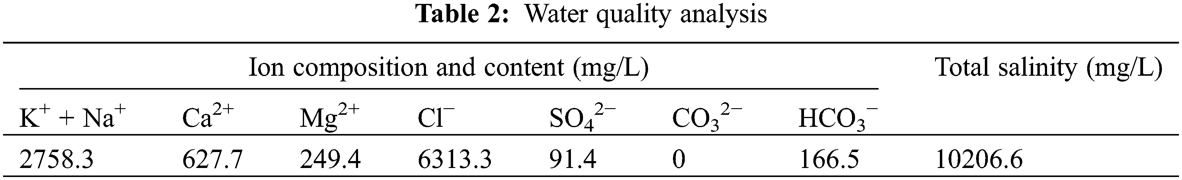
The experimental water was injected water from the oilfield, and the water quality analysis results are shown in Table 2.
The experimental core was an artificial heterogeneous core cemented with quartz sand and epoxy resin. The permeability of the high, middle, and low layers of the heterogeneous core were 10000 × 10−3 μm2, 3000 × 10−3 μm2, and 500 × 10−3 μm2, and their thicknesses were 2 cm, 2 cm, and 0.5 cm, respectively. The external size of experimental core was 4.5 cm × 4.5 cm × 30.0 cm, and the core diagram is shown in Fig. 1.
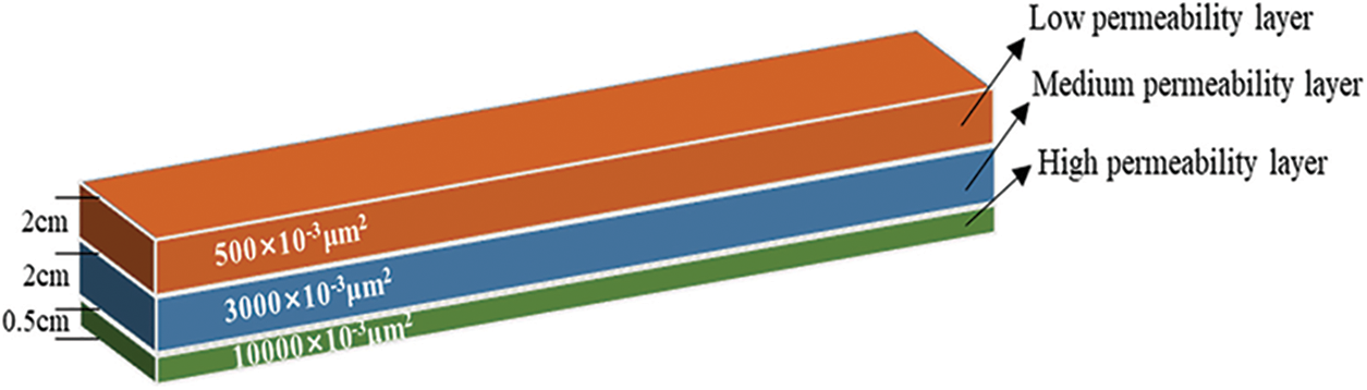
Figure 1: Core diagram
1. The core was vacuumed at room temperature, saturated with formation water, and the pore volume was measured and the porosity was calculated.
2. At the reservoir temperature of 65°C, the core was saturated with simulated oil (70 mPa·s) to calculate the oil saturation.
3. At the reservoir temperature of 65°C, the water flooding reached 98% water cut.
4. The profile control and flooding agent with designed slug size was injected according to the experimental scheme, and then the water flooding reached 98% water cut.
The experimental device is shown in Fig. 2.
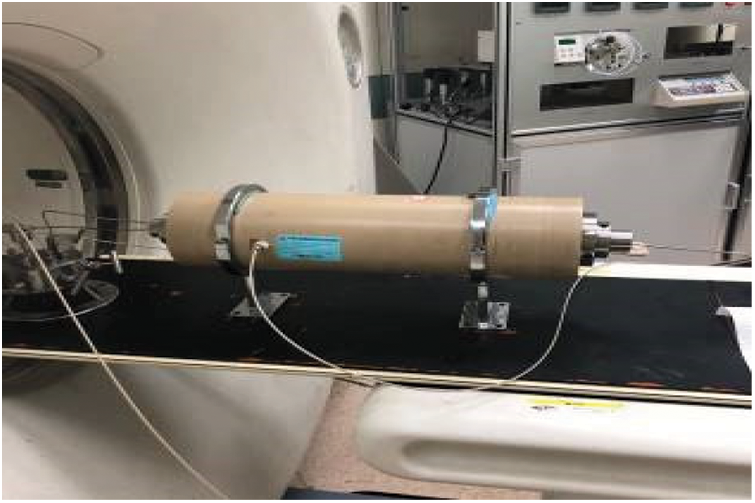
Figure 2: Experimental apparatus diagram
Computed tomography scan experiment: according to the different injection systems, computed tomography was used to scan the entire core in Step 4 to obtain the distribution of oil and water in the core and analyze the remaining oil state.
Nuclear magnetic resonance experiment: after the core was saturated with oil, at the production end of the three different permeability zones, core samples of the same size (0.5 × 1.8 × 3.0 cm3) were cut and immersed in a certain concentration of divalent manganese ion solution to make the manganese ions diffuse into the water phase of the core to shield the signal of the hydrogen in the water. Then nuclear magnetic resonance experiments were carried out to test the signal amplitude of the oil phase in the different permeability layers [12,13]. After the injection of different systems, the water flooding reached 98% water cut and the core samples of the same size (0.5 × 1.8 × 3.0 cm3) were cut again at the production end of the three different permeability zones, immersed in the divalent manganese ion solution, and the signal amplitude of the oil phase in different permeability zones was tested. By comparing the difference in the oil confidence number before and after the injection of different systems, the utilization degree of the remaining oil in the small layers with different permeability was analyzed. The core and the samples for the nuclear magnetic resonance tests are shown in Fig. 3.
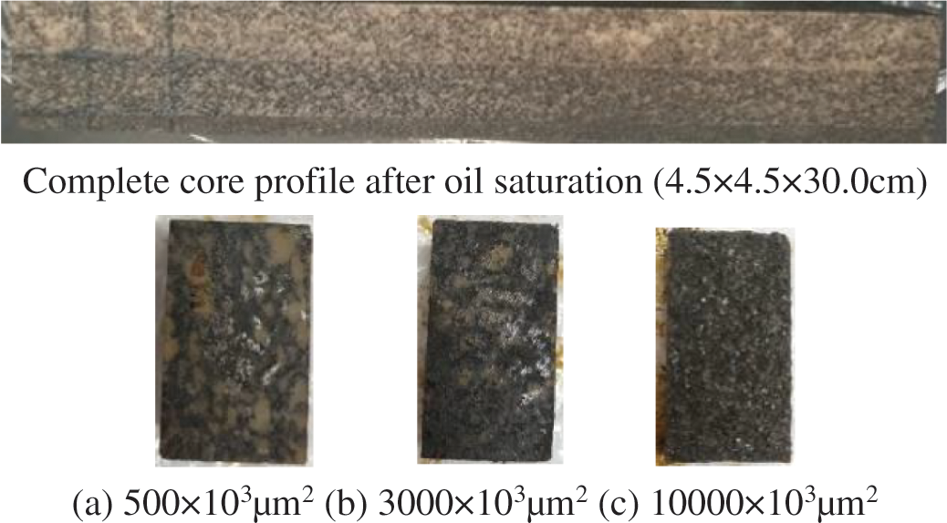
Figure 3: Core cutting picture
Experiment Scheme 1: saturated oil + water flooding to 98% water cut.
Experiment Scheme 2: saturated oil + water flooding to 98% water cut + 0.1PV high-efficiency oil displacement agent (CS = 1200 mg/L) + follow-up water flooding to 98% water cut.
Experiment Scheme 3: saturated oil + water flooding to 98% water cut + 0.1PV polymer microsphere control and displacement agent (CP = 3000 mg/L, slow inflation for 12 h) + follow-up water flooding to 98% water cut.
Experiment Scheme 4: saturated oil + water flooding to 98% water cut + 0.1PV gel plugging agent (set for 48 h) + follow-up water flooding to 98% water cut.
Experiment Scheme 5: saturated oil + water flooding to 98% water cut + 0.1PV gel plugging agent (set for 48 h) + 0.1PV polymer microsphere control (CP = 3000 mg/L, slow inflation for 12 h) + 0.1PV high-efficiency oil displacement agent (CS = 1200 mg/L) + follow-up water flooding to 98% water cut.
3.1 Results of the Recovery Experiment
The oil addition effects of the different injection systems are shown in Table 3.
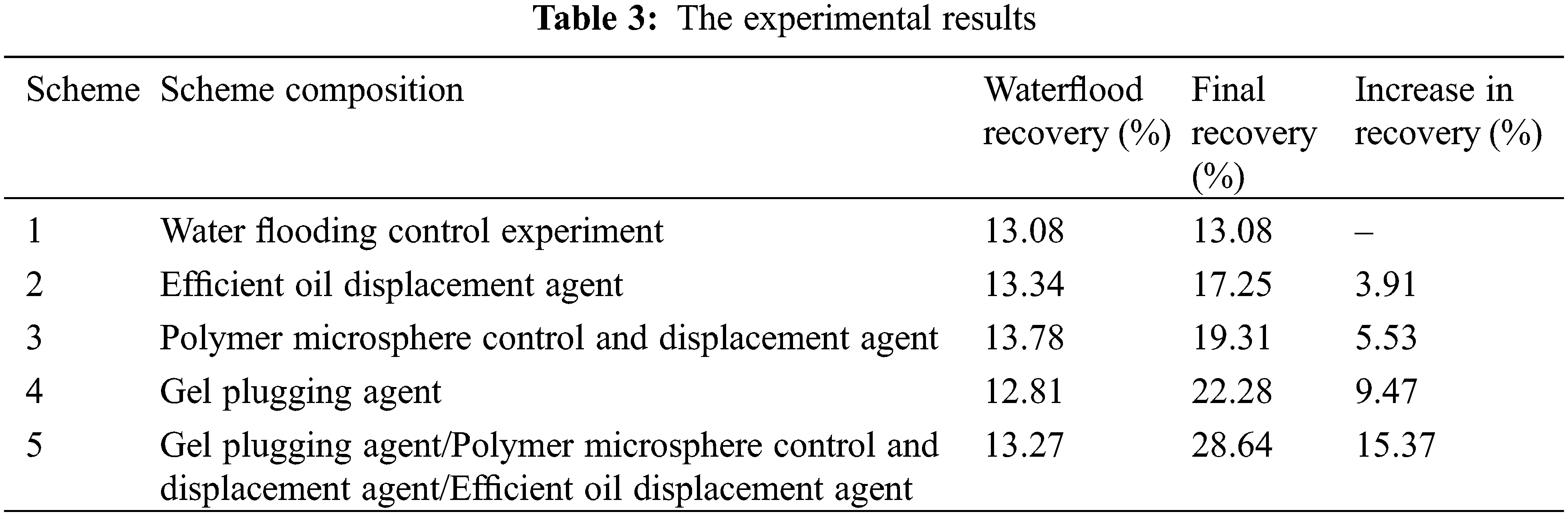
As can be seen from Table 3, due to the large permeability grade difference and strong heterogeneity in the small layers, the effect of the expanding sweep volume during water flooding development was very limited. Therefore, the recovery efficiency from water flooding in the five groups of experiments was low (at about 13%). In terms of EOR increment, the effect of profile control and flooding alone was limited under the condition of severe heterogeneity. In comparison, the combined treatment effect of gel, polymer microsphere control agent, and high-efficiency flooding agent was better (recovery rate increased by 15.37%).
Next, with the help of computed tomography scanning and nuclear magnetic resonance testing technology, the effect of the comprehensive treatment measures on each small layer was quantitatively studied, and the distribution characteristics of the remaining oil after these measures were analyzed.
3.2 Computed Tomography Scan Test Results
The side view of the remaining oil distribution in each scheme is shown in Fig. 4.
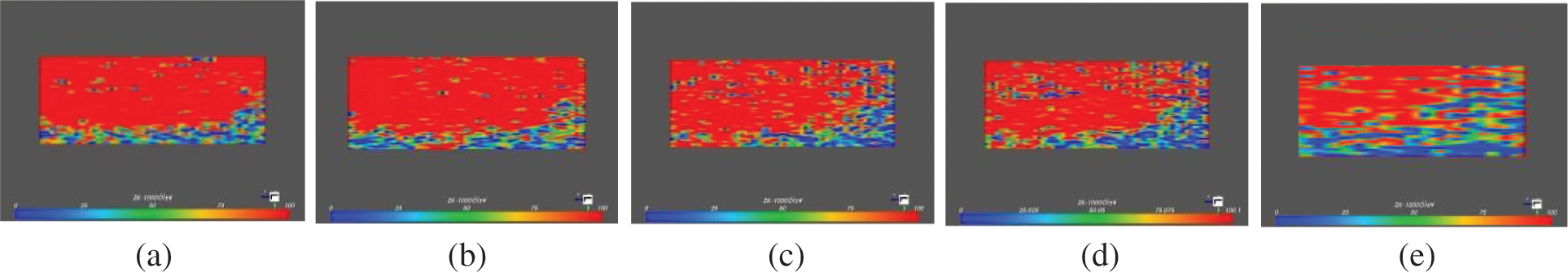
Figure 4: Side view of residual oil distribution (a) Scheme 1, (b) Scheme 2, (c) Scheme 3, (d) Scheme 4 and (e) Scheme 5
Fig. 4 shows the low-permeability, medium permeability, and high-permeability layers from top to bottom; these layers have thicknesses of 2 cm, 2 cm, and 0.5 cm, respectively. The right side of the figure is the inlet end, and the left side is the outlet end. In the figure, red represents oil and blue represents water.
It can be seen from Fig. 4a that the water flooding development is mainly in the bottom high permeability layer. It can be seen from Fig. 4b that the main displacement area of the high-efficiency oil displacement agent is still at the bottom of the high permeability layer. As can be seen from Figs. 4c and 4d, both polymer microspheres and gel plugging agents produce plugging effects near the entrance end of the high permeability layer, and then the water is diverted into the medium and low permeability layer; the oil saturation at the core inlet is obviously reduced. However, due to the small size of the slug and the limited plugging depth, the subsequent water in the middle and low permeability layer flows back to the high permeability area in the core. It can be seen from Fig. 4e that the comprehensive treatment measure of “plugging, profile control, and flooding” can improve contradictions within and between layers. On the one hand, this treatment measure can improve the displacement efficiency of the high permeability layer, and on the other hand, it can expand the sweep effect to the middle and low permeability layers. The oil saturation in the high permeability layer and the inlet end is significantly reduced.
To further study the microscopic characteristics and processes of the remaining oil, the oil phase states in the experimental process were divided into cluster, column, blind end, oil droplet, and oil slick states according to the residual oil contact ratio, shape factor, and other parameters based on the computed tomography scanning results; here, cluster represents the continuous remaining oil and the other states represent the dispersed remaining oil [14–17].
The three-dimensional construction of all the kinds of the remaining oil is shown in Fig. 5.
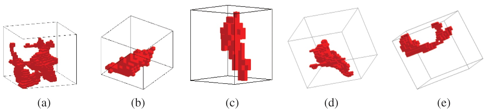
Figure 5: Type of microscopic remaining oil (a) cluster, (b) column, (c) blind end, (d) oil droplet and (e) oil slick
Through computed tomography scan analysis, the types and proportions of the remaining oil in the high, medium, and low permeability zones under different treatments were obtained as shown in Figs. 6–8.
(1) High permeability layer
As can be seen from Fig. 6, compared with water flooding development alone, the use of the efficient oil flooding agent has less influence on the type and proportion distribution of the remaining oil in the high permeability layer (10000 × 103 μm2). After adopting the comprehensive treatment of using the gel plugging agent, the polymer microsphere flooding control agent, and the high-efficiency flooding agent, although the proportion of the remaining oil in the cluster state in the high permeability layer decreased compared with the single profile control and flooding measures, the decrease was small on the whole, indicating that the remaining oil potential in the high permeability layer is not large after water flooding development; it is also necessary to improve the utilization degree of the medium and low permeability layer to further improve the recovery factor.
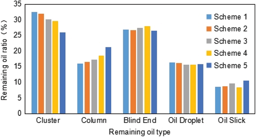
Figure 6: Type and proportion of the microscopic remaining oil (10000 × 103 μm2)
(2) Medium permeability layer
As can be seen from Fig. 7, the single high-efficiency displacement agent and polymer microspheres control agent in Schemes 2 and 3 did not exert a good effect on the remaining oil in the medium permeability layer (3000 × 103 μm2), and the proportion of the different types of remaining oil was not significantly different from that in the water flooding control group. After the injection of the gel plugging agent in Scheme 4, the dominant channel of the high permeability layer was effectively controlled, the liquid absorption of the medium permeability layer increased, and the remaining oil was constantly displaced. The proportion of the cluster state of the remaining oil decreased by 30.8% compared with water flooding, and the proportion of the dispersed state of the remaining oil such as the column and blind end increased significantly. The treatment measure of “plugging, profile control, and flooding” in Scheme 5 that used the gel plugging agent further played a synergistic role of polymer microsphere regulation, flooding agent, and efficient oil displacement agent in expanding the sweep volume and improving the oil washing efficiency [18,19]. The proportion of the cluster-like remaining oil decreased by up to 51.4% as compared with using water flooding alone, and the proportion of the oil droplet and oil film states increased significantly. The treatment measure of “plugging, profile control, and flooding” obviously changed the proportion distribution of the different types of the microscopic remaining oil in the medium permeability layer, indicating that “plugging, profile control, and flooding” treatment can effectively improve the oil recovery from the medium permeability layer.
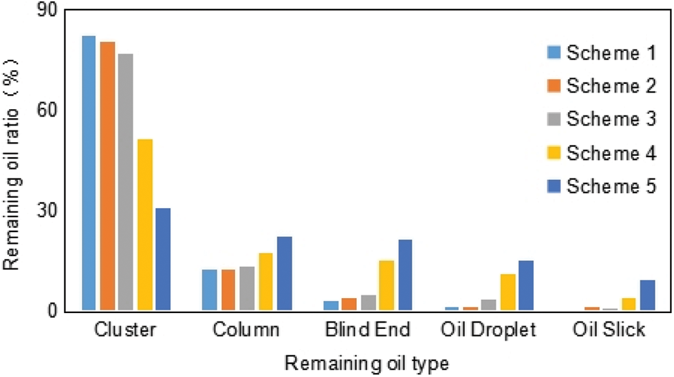
Figure 7: Type and proportion of the microscopic remaining oil (3000 × 103 μm2)
(3) Low permeability layer
As can be seen from the proportion of the remaining oil in the different experimental schemes in Fig. 8, under the heterogeneous condition of a high and low permeability grade difference of 20, the single profile control and flooding measure has almost no influence on the type and proportion of remaining oil in the low permeability layer, and it is difficult to recover oil from the low permeability layer. After “plugging, profile control, and flooding,” the proportion of the cluster state of the remaining oil in the low permeability layer decreased to 59.3%, which is 24.4% lesser than that utilizing water flooding alone, indicating that “plugging, profile control, and flooding” effectively alleviated the interlayer heterogeneity difference.
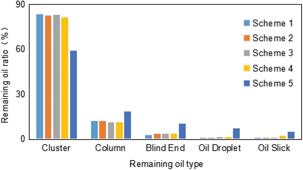
Figure 8: Type and proportion of the microscopic remaining oil (500 × 103 μm2)
Generally speaking, “plugging, profile control, and flooding” measures can displace more remaining oil in the high, middle, and low permeability layers. After plugging the dominant channels of the high permeability layer with the gel plugging agent, polymer microspheres were injected into the medium permeability layer. After the polymer microspheres expand slowly to increase the seepage resistance of the medium permeability layer, the subsequent fluid of the high-efficiency flooding agent will reduce the viscosity of the remaining oil in the low permeability layer, improve the flow of crude oil, and then achieve a significant increase in oil recovery.
3.3 Nuclear Magnetic Resonance Test Results
Combined with the results of the recovery experiment in Table 3, it can be found that, compared with water flooding or the single measure of plugging or profile control or flooding, the “plugging, profile control, and flooding” measure provides the largest increase in recovery and has a significant impact on the remaining oil types in the high, medium, and low permeability zones, but the final recovery is only 28.64%, which still has great potential for improvement.
Next, with the help of nuclear magnetic resonance experiments, the remaining oil signal amplitudes of Schemes 1 and 5 were compared to analyze the remaining oil usage in different pores after the “plugging, profile control, and flooding” measures.
The nuclear magnetic resonance T2 map is usually a bimodal curve, and the fluid in the macropores is under a weak force and has a long relaxation time. Therefore, the concave point in the middle of the bimodal curve is the critical value of the large and small pores, with the right representing the large pores and the left representing the small pores [20–23]. Table 4 and Figs. 9–11 show the nuclear magnetic resonance experimental results of each small layer after the water flooding control experiments and after the “plugging, profile control, and flooding” measures.
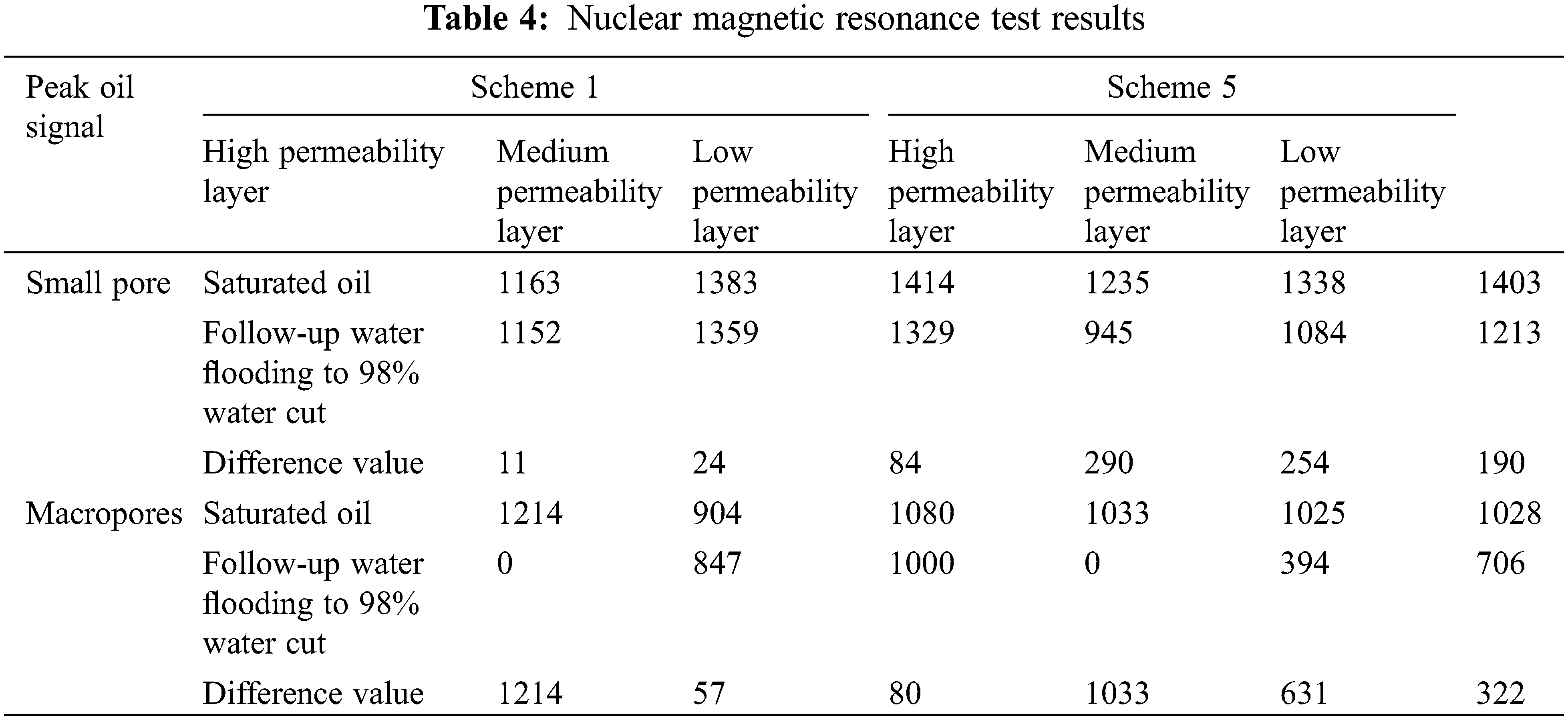
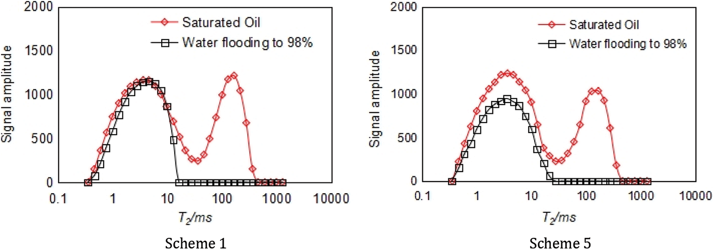
Figure 9: Nuclear magnetic resonance T2 spectrum test results (10000 × 10−3 μm2)
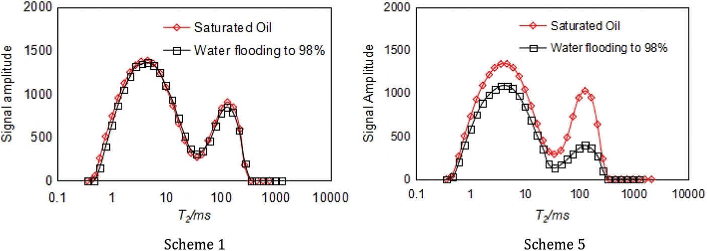
Figure 10: Nuclear magnetic resonance T2 spectrum test results (3000 × 10−3 μm2)
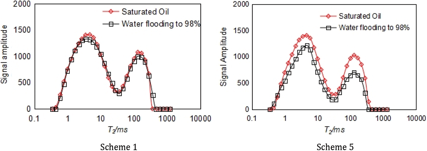
Figure 11: Nuclear magnetic resonance T2 spectrum test results (5000 × 10−3 μm2)
(1) High permeability layer
As can be seen from Fig. 9, after water flooding, almost no crude oil signal can be detected in the large pores of the high permeability layer, indicating that the crude oil in the large pores has been fully displaced, while the signal amplitude of the crude oil in the small pores has hardly changed. By contrast, after the “plugging, profile control, and flooding” measures, the signal amplitude of the crude oil in the small pores decreased to a certain extent, indicating that the “plugging, profile control, and flooding” measures effectively blocked the large pores in the high permeability layer, and the subsequent fluid flow occurred at the micro-level, which enlarged the sweep effect on the small pores. Combined with the oil washing effect of the efficient oil displacement agent, the remaining oil in the high permeability layer was further displaced.
(2) Medium permeability layer
As shown in Fig. 10, due to the serious longitudinal heterogeneity between medium and high permeability layers, it is difficult for water flooding development to displace the remaining oil in the medium permeable layer, and the signal amplitude of the remaining oil in the medium permeability layer remains the same before and after water flooding. After “plugging, profile control, and flooding” measures are adopted, the signal amplitude of the crude oil in the medium permeability layer’s large pores decreases significantly, and the signal amplitude of the oil in the medium and small pores also decreases to a certain extent, indicating that the “plugging, profile control, and flooding” treatment’s effect is significant. Compared with water flooding, “plugging, profile control, and flooding” treatment can fully help to displace the remaining oil in the medium permeability layer, which not only alleviates the interlayer difference, but also improves the micro-heterogeneity within the layer, so that both large and small pores are affected, and the extent of recovering the remaining oil in the medium permeability layer is significantly enhanced.
(3) Low permeability layer
Fig. 11 shows the variation of the remaining oil’s signal amplitude before and after the treatment measures on the low permeability layer. As can be seen from Fig. 11, the amplitude of the crude oil signal in the low permeability zone decreased after the “plugging, profile control, and flooding” measures, but the decrease was not large, which is also confirmed by the computed tomography scan results. The reason is that when the permeability difference between the high and low permeability layers is large (the value of permeability differential is 20), it is difficult for the polymer microspheres to improve the liquid absorption capacity of low permeability layer while playing the role of profile control and flooding in medium permeability layer, and the effect of recovering the remaining oil in the low permeability layer is very limited.
Combining the results of the computed tomography scanning and the nuclear magnetic resonance experiments, it can be seen that “plugging, profile control, and flooding” measures can manage the different permeability layers step by step at the macro-level and can improve the sweep effect of remaining oil in small pores at the micro-level. Compared with the single profile control and flooding system, “plugging, profile control, and flooding” measures can play a synergistic role among systems, and have great advantages and application potential. However, to further enhance the effect of “plugging, profile control, and flooding” measures and fully recover the large amount of remaining oil distributed in the small pores of the low and medium permeability layers, it is necessary to consider the combination of polymer microspheres with different particle size and expansion performance and efficient oil displacement agents. This will help to conduct multiple rounds of stepwise control and flooding after using gel plugging agents to reduce the effect of permeability differences and pore size differences in medium and low permeability layers.
(1) The comprehensive treatment measures of using gel plugging agents together with polymer microsphere flooding control agents and high-efficiency flooding agents can increase oil recovery by 15.37%.
(2) According to the computed tomography scan results, the comprehensive treatment measures of using gel plugging agents with polymer microsphere flooding control agents and high-efficiency flooding agents can reduce the cluster state of the remaining oil in the medium permeability layer by 51.4%, reduce the cluster state of the remaining oil in the low permeability layer by 24.4%, disperse the continuous phase of the remaining oil into the micro-discontinuous phase, and improve the recovery degree of oil from the medium and low permeability layers.
(3) Nuclear magnetic resonance results show that the remaining oil in the high permeability layer after water flooding mainly accumulates in the small and medium pores, and the development potential is limited. Using a gel plugging agent with a polymer microsphere flooding control agent and a high-efficiency flooding agent can effectively improve the water flooding profile by treating and adjusting large channels and small and medium pores in a step-by-step manner; this enhances the recovery degree of oil from the small and medium pores and reduces the signal amplitude of the crude oil in the pores.
(4) According to the comprehensive computed tomography scan and nuclear magnetic resonance test results, for reservoir conditions with strong heterogeneity, after comprehensive treatment, the remaining oil is mainly distributed in the small pores of the low and medium permeability layers in cluster, column, and blind end states, which have great potential for recovery. The next step would be to conduct multiple rounds of step-by-step profile control by combining microspheres with different particle sizes and expansion properties with high-efficiency flooding agents after using gel plugging agents to fully recover the remaining oil in medium and low permeability layers with different pore sizes and permeabilities.
Funding Statement: The authors gratefully acknowledge the financial support from the National Science and Technology Major Special Project (2016ZX05058-003).
Conflicts of Interest: The authors declare that they have no conflicts of interest to report regarding the present study.
1. Clarke, A., Howe, A. M., Mitchell, J., Staniland, J. (2016). How viscoelastic-polymer flooding enhances displacement efficiency. SPE Journal, 21(3), 675–686. DOI 10.2118/174654-PA. [Google Scholar] [CrossRef]
2. Amirian, E., Dejam, M., Chen, Z. (2018). Performance forecasting for polymer flooding in heavy oil reservoirs. Fuel, 216, 83–100. DOI 10.1016/j.fuel.2017.11.110. [Google Scholar] [CrossRef]
3. Xie, K., Cao, B., Lu, X. G., Jiang, W. D., Zhang, Y. B. et al. (2019). Matching between the diameter of the aggregates of hydrophobically associating polymers and reservoir pore-throat size during polymer flooding in an offshore oilfield. Journal of Petroleum Science & Engineering, 177(6), 558–569. DOI 10.1016/j.petrol.2019.02.076. [Google Scholar] [CrossRef]
4. Zhang, J. L., He, S. M., Liu, T. J., Ni, T. L., Zhou, J. et al. (2021). Visualization of water plugging displacement with foam/gel flooding in internally heterogeneous reservoirs. Fluid Dynamics & Materials Processing, 17(5), 931–946. DOI 10.32604/fdmp.2021.015638. [Google Scholar] [CrossRef]
5. Wang, J., Sun, J., Liu, D., Zhu, X. (2019). Production capacity evaluation of horizontal shale gas wells in Fuling district. Fluid Dynamics & Materials Processing, 15(5), 613–625. DOI 10.32604/fdmp.2019.08782. [Google Scholar] [CrossRef]
6. Unsal, E., Berge, A., Wever, D. (2018). Low salinity polymer flooding: Lower polymer retention and improved injectivity. Journal of Petroleum Science and Engineering, 163(1), 671–682. DOI 10.1016/j.petrol.2017.10.069. [Google Scholar] [CrossRef]
7. Meng, X. H., Zhao, P., Wang, H. S., Han, Y. G., Zhang, X. R. et al. (2020). Research and application of multi-slug combination profile control and flooding after polymer flooding. Complex Hydrocarbon Reservoirs, 13(4), 81–85. DOI 10.16181/j.cnki.fzyqc.2020.04.015. [Google Scholar] [CrossRef]
8. Liang, S. C., Li, Q., Lv, X., Zhou, Y. X., Cao, W. J. et al. (2018). Effect of multi-stage profile control and displacement technology and remaining oil distribution. Petroleum Geology & Oilfield Development in Daqing, 37(6), 108–115. DOI 10.19597/J.ISSN.1000-3754.201801001. [Google Scholar] [CrossRef]
9. Wang, H. S., Wei, J., Zhang, Z. J., Shi, D. S., Xu, L. et al. (2021). Experimental study on enhanced oil recovery by combination of profile control and displacement. Complex Hydrocarbon Reservoirs, 14(2), 80–84. DOI 10.16181/j.cnki.fzyqc.2021.02.015. [Google Scholar] [CrossRef]
10. Wang, C., Zhou, Y. X., Yang, Z. H., Song, J. F., Li, Y. C. (2019). Research and application of combination regulation and flooding technology for high temperature and high salt oil reservoir in Weizhou Oilfield. Chemical Engineering & Equipment, (4), 107–109. DOI 10.19566/j.cnki.cn35-1285/tq.2019.04.045. [Google Scholar] [CrossRef]
11. Rong, X. M., Zhang, Y., Du, X., Liu, Y., Sun, P. F. et al. (2020). Experimental study for nanosphere combination flooding technology. Petrochemical Industry Application, 39(5), 76–78. [Google Scholar]
12. Li, Z. T. (2011). Oil saturation in core is studied by NMR 2D spectroscopy. China: Graduate School of Chinese Academy of Sciences (Institute of Percolation Fluid Mechanics). [Google Scholar]
13. Golsanami, N., Sun, J., Zhang, Z. (2016). A review on the applications of the nuclear magnetic resonance (NMR) technology for investigating fractures. Journal of Applied Geophysics, 133(6), 30–38. DOI 10.1016/j.jappgeo.2016.07.026. [Google Scholar] [CrossRef]
14. Raeini, A., Bijeljic, B., Blunt, M. (2015). Modelling capillary trapping using finite-volume simulation of two-phase flow directly on micro-CT images. Advances in Water Resources, 83(2–3), 102–110. DOI 10.1016/j.advwatres.2015.05.008. [Google Scholar] [CrossRef]
15. Georgiadis, A., Berg, S., Makurat, A., Maitland, G., Ott, H. (2013). Pore-scale micro computed tomography imaging: Non-wetting-phase cluster-size distribution during drainage and imbibition. Physical Review E: Stat Nonlinear Soft Matter Physical, 88(3), 033002. DOI 10.1103/PhysRevE.88.033002. [Google Scholar] [CrossRef]
16. Iglauer, S., Fernø, M., Shearing, P., Blunt, M. J. (2012). Comparison of residual oil cluster size distribution, morphology and saturation in oil-wet and water-wet sandstone. Journal of Colloid and Interface Science, 375(1), 187–192. DOI 10.1016/j.jcis.2012.02.025. [Google Scholar] [CrossRef]
17. Iassonov, P., Gebrenegus, T., Tuller, M. (2009). Segmentation of X-ray computed tomography images of porous materials: A crucial step for characterization and quantitative analysis of pore structures. Water Resources Research, 45, 706–715. DOI 10.1029/2009WR008087. [Google Scholar] [CrossRef]
18. Bao, W. B., Lu, X. G., Liu, Y. G., Li, Y. Y., Zhang, Y. et al. (2019). Oil increasing effect and mechanism of microsphere/high efficiency oil displacement agent compound system. Petrochemical Technology, 48(8), 843–849. [Google Scholar]
19. Liu, W. H., Zheng, Y. F., Tie, L. L., Xu, G. R., Li, X. et al. (2018). Study on the influence of injection mode of polymer microsphere/surfactant composite system on control and flooding effect. Chemical World, 59(9), 598–603. DOI 10.19500/j.cnki.0367-6358.20180118. [Google Scholar] [CrossRef]
20. Mitchell, J., Gladden, L. F., Chandrasekera, T. C., Fordhamet, E. J. (2014). Low-field permanent magnets for industrial process and quality control. Progress in Nuclear Magnetic Resonance Spectroscopy, 76, 1–60. DOI 10.1016/j.pnmrs.2013.09.001. [Google Scholar] [CrossRef]
21. Golsanami, N., Zhang, X., Yan, W., Yu, L., Dong, H. et al. (2021). NMR-based study of the pore types’ contribution to the elastic response of the reservoir rock. Energies, 14(5), 1513. DOI 10.3390/en14051513. [Google Scholar] [CrossRef]
22. Di, Q. F., Zhang, J. N., Hua, S., Chen, H. J., Gu, C. Y. (2017). Visualization experiments on polymer-weak gel profile control and displacement by NMR technique. Petroleum Exploration and Development, 44(2), 270–274. DOI 10.1016/S1876-3804(17)30033-2. [Google Scholar] [CrossRef]
23. Hamada, G., Abushanab, M. M. (2008). Better porosity estimate of gas sandstone reservoirs using density and NMR logging data. Society of Petroleum Engineers, 13(3), 47–54. DOI 10.2118/106627-ms. [Google Scholar] [CrossRef]
 | This work is licensed under a Creative Commons Attribution 4.0 International License, which permits unrestricted use, distribution, and reproduction in any medium, provided the original work is properly cited. |