| Fluid Dynamics & Materials Processing |
DOI: 10.32604/fdmp.2022.018938
ARTICLE
Modeling of Heat Transfer and Steam Condensation Inside a Horizontal Flattened Tube
1Mechanical Engineering Department, Faculty of Engineering, Mustansiriyah University, Baghdad, 10052, Iraq
2School of Mechanical and Electrical Engineering, University of Southern Queensland, Queensland, 4350, Australia
3Engineering Collage, University of Zakho, Zakho, 42002, Iraq
4Energy and Renewable Energies Technology Center, University of Technology, Baghdad, 10066, Iraq
*Corresponding Author: M. Gh. Mohammed Kamil. Email: ehph015@uomustansiriyah.edu.iq
Received: 25 August 2021; Accepted: 12 November 2021
Abstract: This work investigates the steam condensation phenomena in an air-cooled condenser. The considered horizontal flattened tube has a 30 mm hydraulic diameter, and its length is a function of the steam quality with a limit value between 0.95 and 0.05. The mass flow rate ranges from 4 to 40 kg/m2.s with a saturated temperature spanning an interval from 40°C to 80°C. A special approach has been implemented using the Engineering Equation Solver (EES) to solve a series of equations for the two-phase flow pattern and the related heat transfer coefficients. A wavy-stratified structure of the two-phase flow has been found when the mass rate was between 4 and 24 kg/m2.s. In contrast, an initially annular flow is gradually converted into a wavy stratified flow (due to the condensation process taking place inside the flattened tube) when the considered range ranges from 32 to 40 kg/m2.s.
Keywords: Condensation; flow pattern structure; heat transfer rate; flow in horizontal pipe; flow behaviour; EES modelling
Nomenclature
| A | Tube cross-section area, [m2] |
| Al | Liquid cross-section area, Al = A (1-ε), [m2] |
| Ald | Dimensionless cross-sectional area occupied by liquid, Ald = Al/d2 |
| AV | Vapor cross-sectional area, Av = A ε, [m2] |
| Avd | Dimensionless cross-sectional area occupied by vapor, Avd = Av/d2 |
| cp | Specific heat, [J/(kg.K)] |
| Dh | Hydraulic diameter, [m] |
| Frl | Liquid Froude number, G2/( |
| g | Acceleration of gravity, [m/s2] |
| G | Total mass flow rate (mass velocity) of liquid and vapor [kg/(m2.s)] |
| Gstrat | Transition mass velocity of stratified flow [kg/(m2.s)] |
| Gwavy | Transition mass velocity of wavy flow [kg/(m2.s)] |
| h | Heat transfer coefficient [W/(m2.K)] |
| ifg | Condensation latent heat, [J/kg] |
| J | Dimensionless velocity [-] |
| k | Thermal conductivity, [W/(m.K)] |
| Nu | Nusselt number, the subscript specifies the characteristic length, (hDh)/kl |
| P | Pressure, [N/m2] |
| Pr | Prandtl number [-] |
| r | Inside radius of tube [m] |
| T | Temperature [K] |
| x | Vapor quality [–] |
| Xtt | Martinelli parameter with both phases turbulent [–] |
| dZ | Increment in the condensation tube |
| dx | The change of the quality of steam along the condensation process |
| Greek symbols | |
| Δ | Difference |
| ε | Vapor void fraction [–] |
| εh | Homogenous void fraction [-] |
| εra | Rouhani-Axelsson void fraction [-] |
| μ | Dynamic viscosity [N s/m2] |
| θ | Angle of the upper portion tube not wetted by stratified liquid [rad] |
| θstrar | Stratified angle about the upper perimeter of the tube [rad] |
| ρ | Density [kg/m3] |
| σ | Surface tension [N/m] |
| Subscripts | |
| bot | Bottom portion |
| c | Liquid condensate |
| crit | Critical |
| f | Film |
| g | Vapor |
| l | Liquid |
| r | Reduced |
| sat | Saturated |
| TP | Two-phase |
| up | Upper portion |
| w | Wall |
Condensation phenomenon is deployed in many industrial applications of equipment such as air-cooled power generation plants, desalination, air-conditioning refrigerant, concentrated solar power, chemical processes and nuclear power plants [1–4]. Usually, the two-phase flow pattern describes the behaviour of the condensation and flow characteristic along the inner wall of the tube, so based on the two-phase flow pattern, the pressure drop and the heat transfer rate, whether in a horizontal or a vertical tube, can be estimated and predicted. In order to obtain an effective design with high condensation efficiency, flow behaviour inside the condenser, heat transfer coefficient, and pressure drop and void fraction of the two-phase flow inside the condenser need to be considered.
In a horizontal tube, usually, the steam condenses along the inner wall of the tube when the steam forward movement on the way to liquid phase across a varies of qualities. Therefore to understand the two-phase flow development in a horizontal tube, it is important to recognize the flow models along the pipe. Because of the significance of orientation, interaction between gravity, buoyancy, surface tension and inertia forces need to be considered in computational predictions [5]. Flow pattern structure and overall pressure drop [6], are of interest in the design while the size of the tube is strongly dependent on the appropriate estimation of the two-phase hydrostatic pressure drop that requires understanding the flow pattern and correct prediction of the void fraction at any position and flow rate.
The two-phase flow has many different flow patterns, which can be obtained based on the variation of the void fraction [7]. In addition, the momentum and heat processes are also influenced substantially by flow pattern models. Therefore, it is appropriate for engineers to determine which type of a flow model depends on certain parameters, such as the quality of the steam, the diameter of the tube, the flow rate and the properties of the fluid.
Both the shear force of a vapor and surface tension force are dominating in the tubes when the tube diameter is less than 3 mm [8]. Subsequently, the two-phase flow pattern becomes annular-mist or annular flow when the void fraction has a high value. In contrast, the pattern will be slug or plug at a low or medium value of the void fraction. In a large tube diameter, the flow with high void fraction, gravity and shear forces are dominating, which depends on the velocity of the vapor. When the vapor’s velocity is low, the film of condensation forms around the upper perimeter of the tube, flows down to the lower part of the tube and accumulates. The flow pattern models can be classified as wavy and stratified flow. The flow pattern models can include annular-mist, annular and wavy-annular flow models. However, the transformation from the first category flow model to another flow model such as bubbly, plug and slug depends on an increase in the liquid hold-up (1-α).
Chato [5] reported that the gravity force dominates when the flow pattern is stratified with a smooth interface. While the wavy flow model is formed by increasing the vapor velocity, which gives waves [6]. With a high void fraction and further increase of vapor velocity, the wavy flow model is unstable, and the waves of the liquid transform to cover the perimeter of the tube, and then, with increasing velocity, a uniform annular flow model will be generated. A wavy-annular flow model is observed before reaching the annular flow model [5]. At high vapor velocities, the model is transferred to the annular–mist flow model that is characterized by the ability to entrain the liquid droplets in the vapor core because the tips of the waves on the liquid film are broken off by the vapor flow.
Baker [9] presented two-phase flow pattern maps, considered one of the earliest maps for flow models that can be used for an adiabatic mixture of oil-water and air-water with a range of tube diameter from 101.4 mm to 25.4 mm. Identical to the Baker map, Mandhane et al. [10] improved a flow model map that depends on a wide database of about 5935 examinations. The right prediction of the flow model is based on the Mandhane map for 68% of the examinations vs. 42% for the Baker map. However, Taitel et al. [11] presented the most efficient flow model map, which covers five flow models: dispersed bubble, intermittent (plug and slug), stratified–wavy, annular, and stratified smooth. The map was investigated successfully for adiabatic flows by other researchers. Soliman [12] developed another procedure to predict the flow regime transitions for the condensation process by classifying the flow model into three regimes: wavy, annular and mist. The author specified two criteria to transition between flow regimes, one for the annular-to-mist and another for the wavy-to-annular transition. It is necessary to clarify that Soliman [12] considered that the wavy flow regime involves wavy, slug, and stratified flow. Even though these flow patterns are significantly dissimilar from the point of view for flow pattern classification, especially concerning the wavy interface stabilization. Dobson et al. [13] submitted a new model of heat transfer which is related to the two-phase structure such as Stratified flow, wavy flow, wavy-annular flow, and annular flow where both the convective and film-wise condensation inside circular tubes were included. El Hajal et al. [14] proposed a new two-phase version for flow pattern map inside the horizontal plain tubes for the process of condensation, which is originally formed by Kattan et al. [15,16] for the process of boiling. The new map involves a new defined logarithmic mean void fraction (LMε) method for the determination of vapor void fractions within a range from low pressures to pressures close to the critical point. Indeed, the validity of the new (LMε) method has been verified by using the thermal condensation model for the annular flow; also, the modified map gave good results after comparing it to several recent flow patterns. Shah [17] submitted a new method of correlations to predict the heat transfer coefficient published in 1979, which was examined with various fluids such as refrigerant, hydrocarbon, and water. These modified correlations depend on heat transfer regimes that were set according to boundaries represented by equations given by Shah [18]. The modified correlations are in good agreement with a database that corresponds to the analytical solutions for Nusselt number that covers most turbulent flows to the laminar flow cases. The database has been used to verify the validity of the correlation, and included many types of fluid such as water, refrigerants, and organics that condense inside tubes with vertical, horizontal, and downward inclined orientations. In 2013, Shah [19] introduced the development of a general correlation to examine the relationship between laminar, mixed heat transfer regimes and flow pattern structures. The correlation was used to address the flow in horizontal tubes at very low flow rates. The author also proposed a new model [20] for the effect of inclination from +90° to −90° and diameter range from 1.23 to 14.81 mm with mass flux range from 11.2 to 699 kg/m2.s. Mahdi et al. [21] suggested a mathematical model to predict the local heat transfer coefficient during a condensation process in a horizontal flattened tube. The results revealed that the proposed mathematical model can predict the local heat transfer coefficient, but the resolution of steam condensation heat transfer coefficient still needs more investigation as the water vapor was used as a working fluid. Several studies have submitted a heat transfer model at the certain structure of the two-phase flow. Ahn et al. [22] developed a stratified flow steam condensation heat transfer model that comprises two types of heat transfer coefficient correlations and a heat partition angle correlation that separates the two heat transfer zones at actual experimental heat transfer data. The experimental data for model development were collected using circular tubes with inner diameters of 30–45 mm and inclination angles of 0–10 at pressures ranging from 1–67 bar and mass fluxes ranging from 10 to 329 kg/m2.s. Sereda et al. [23] introduced an experimental study to assess the heat transfer during the condensation process of refrigerants R22 and R407C have a saturated condensing temperature of 40 C in a smooth horizontal tube has an internal diameter of 17 mm, while the range of mass velocity was from 6 to 57 kg/m2.s and the quality of vapor from 0.95 to 0.23. The particular devices were used to measure the heat flux at circumferential of the condensation tube and the features of the heat transfer during the streamlet flow of the phases. The authors presented a CFD simulation through the heat transfer of condensing vapor to the system of cooling water by a cylinder that has a thick wall. The CFD model was evaluated using a practical experiment, which revealed that the results agreed with an error range of 7% to 20%. Under stratified flow conditions, this approach could generalize the experimental results on the condensation of refrigerants R22, R134a, R123, R125, R32, R410a, propane, isobutane, propylene, dimethyl ether, carbon dioxide, and methane with accuracy of 30%. Abdulkareem et al. [24] experimentally studied the influence of a 90-degree elbow with an internal diameter of 67 mm. Its curvature radius in the horizontal pipe after the bend is 153.5 mm under varied gas and fluid superficial speed ranges. The results showed that a stratified-wavy flow pattern was seen as a dominant flow pattern at low liquid and gas flow rates. In comparison, a high variety of gas flow rates in the horizontal tube has been maintained in waving and semi-annular flow patterns. The results also showed that the flux patterns in the horizontal gas pipes were observed when fluxes rose at a high liquid fluid flow rate, bubbling, plug, slug, stratified wavy and wavy-annular.
Indeed, many studies investigated the condensation process within different considerations, but there is a lack of information about the mathematical model that can be used to predict the rate of heat transfer which is related to the certain structure of flow pattern during the steam condensation in the flattened tube at low mass flow rate. However, the current work is to present a mathematical model that can be used to predict the mechanism of the heat transfer in the certain structure of the two-phase flow pattern in the steam condensation process inside a flattened horizontal tube which enhanced our previous work presented in [21].
2 Mathematical Model Development
The Engineering Equation Solver (EES) (Klein) platform Professional V9.478 (2013) was used to investigate the two-phase flow patterns by solving sets of equations that represent the heat transfer coefficient for the condensation phenomena inside the flattened tube of an air-cooled steam condenser.
Certain boundary conditions were used in EES, the range of mass velocity rate was between 4 and 40 kg/m2.s, steam saturated temperature ranged from 40°C to 80°C and steam quality from 0.95 to 0.05.
A horizontal flattened tube as in Fig. 1, has a hydraulic diameter of about 30 mm, and the length was a function of the steam quality with a limited value from 0.95 to 0.05 as presented in Eq. (1). Eq. (1) was integrated using ΔT = 2°C and considered length change for a tube (z) with a two-phase heat transfer coefficient (h) and the efficiency of the steam (x).
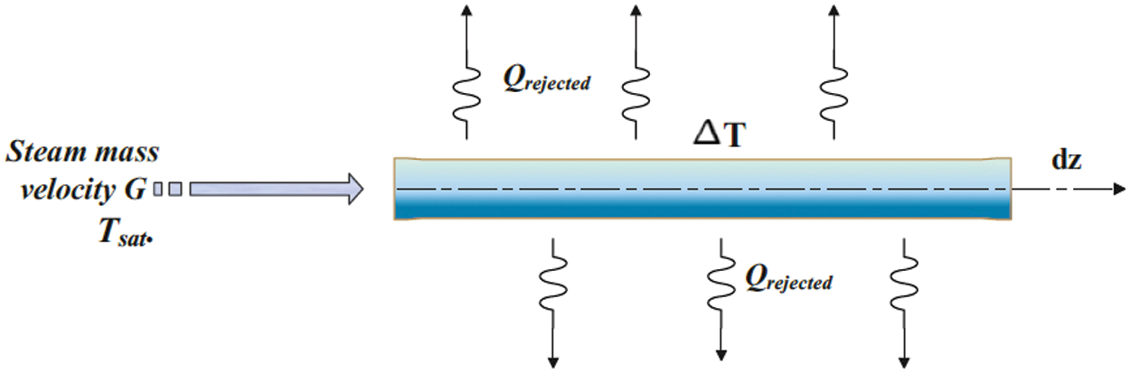
Figure 1: Boundary conditions
The heat transfer model was controlled by the predominant flow structure to analyze the model of heat transfer during the steam condensation process. The flow structures were classified into two categories: shear-dominated and gravity-dominated flows. In the shear force dominated flow model, forced-convection was controlling the condensation heat transfer model. This structure was defined by heat transfer coefficients that were significantly dependent on the steam quality and mass flux. While in the gravity force dominated flow model, a laminar film condensation at the upper part of the tube was controlling the heat transfer model in which the heat transfer coefficients are depended on the temperature difference between the wall and the fluid but were nearly independent of mass velocity. The criteria of dominant flow inside the air-cooled steam condenser tubes are changeable as a result of changing operational situations, and that is why it is obligatory to define the dominant criterion to subsequently move to the analysis of the case. Rosson [25] is used as a parameter to solve this problem, which depends on the gathering of two dimensionless parameters as shown below:
Martinelli’s parameter:
Dimensionless speed:
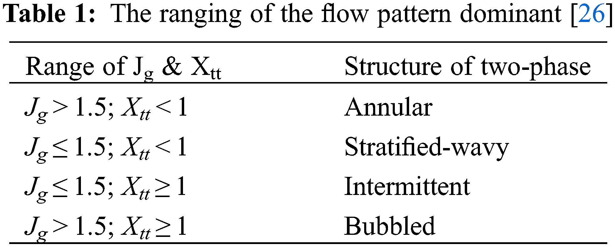
After the implementation of Eqs. (2) and (3), Table 1 presents the range of dimensionless speed and Martinelli,’s parameter for different types of two-phase flow pattern.
The structure flow model was determined according to the abovementioned criteria, however, the model proposed by Soliman [12] will be adopted to predict the heat transfer model.
Stratified wavy flow
At the medium and low velocity of steam, stratified wavy flow is formulated. In this flow pattern, gravity forces control the flow. The condensation flow structure includes two types of heat transfer models: a film-wise condensation had occurred in the upper part of the tube with overlap effects due to shear of vapor and forced convective heat transfer in the lower part of the tube. Dobson et al. [13] analyzed this flow structure under these criteria, mass velocity was less than 500 kg/m2.s, steam velocity was higher than 0.5 m/s and Soliman modified Froude number (FrSo) was less than (7), which can be represented as:
The Galileo number and Reynold’s number assuming liquid phase flowing alone can be determined as follows:
The average of heat transfer coefficient in this cross-section for this type of flow structure can be represented by:
– The film-wise condensation heat transfer coefficient for the upper part of the tubes:
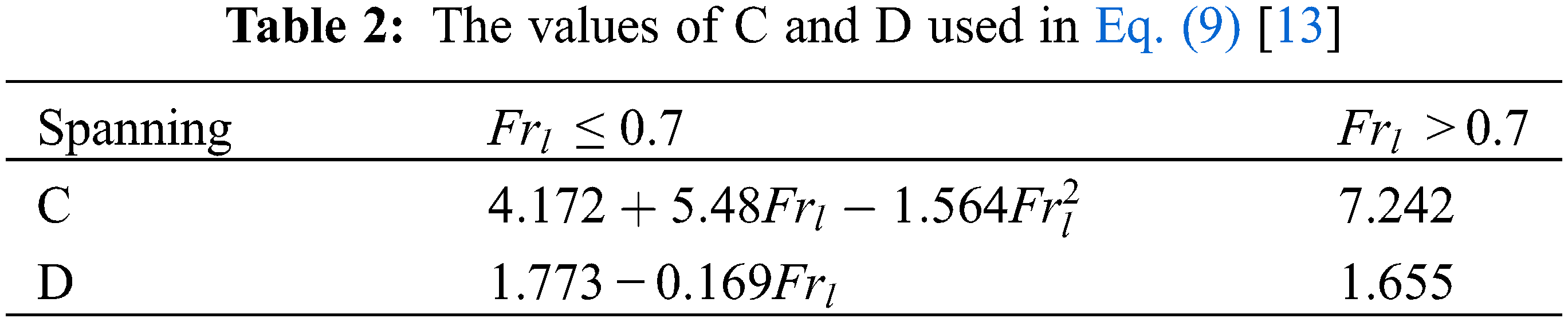
– For the liquid part, the heat transfer coefficient as:
The C and D are constants that can be represented as in Table 2.
– To determine the wavy-stratified angle between the steam portion and the condensate portion, as shown in Fig. 2, El Hajal et al. [14] proposal can be used, which depends on the definition of Gstrat, Gwavy, θstrat. And the void fraction
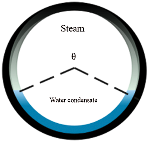
Figure 2: Wavy-stratified angle
The global term of local heat transfer coefficient hTP at any cross-section of the tube is:
Annular Flow
An annular flow structure is formed at a high velocity of steam when the effect of shear force for the steam is pronounced more than the gravity force, while the condensate film covers the circumference of the inner diameter of the tube. According to Dobson et al. [13], heat transfer coefficient equation has significant acceptance and can be utilized in air-cooled heat exchangers that work under this type of flow, which is expressed by:
3 Validation of the Mathematical Model
The Engineering Equation Solver (EES) has been used to solve a set of methodical equations and empirical equations, the mathematical model of the current study, has been validated with experimental results from the literature. The experimental results and operating conditions of the two-phase flow development has been presented by Mahmood et al. [27] in order to predict the flow pattern in a horizontal tube have been launched into the EES of the current study. The EES model showed a good agreement with the experimental result in terms of the flow pattern at the developed region. The EES predicted a wavy-stratified flow pattern at the same operating condition of the experimental study of [27–29]. The superficial velocity Jg and Martinelli Xtt values were 0.2598 (less than 1.5) and 0.000467 (less than 1), as in Table 1, respectively. The findings that have been obtained from [23] confirmed that as well. Fig. 3 presents the two-phase flow behavior in the developed region at mass flow rate of 2.1 ± 0.2 g/s. Indeed, Table 1 from [23] and the image of the experimental results from [24] confirmed the EES model for the current study to predict the two-phase flow pattern with good agreements.
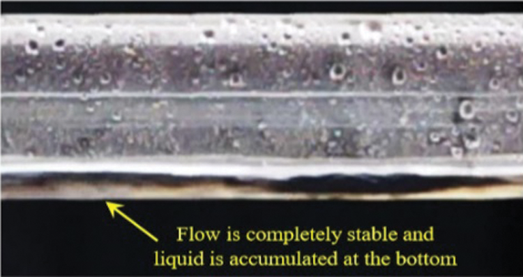
Figure 3: Image of experimental results of the two-phase flow development at the developed region [24]
This section discusses the results that are obtained from the mathematical model using Engineering Equation Solver (EES), after the formation of special codes for the equations of the two-phase flow pattern and heat transfer coefficients.
Both Eqs. (2) and (3) were used to estimate the Martinelli parameter and dimensionless speed for prediction of the two-phase flow structure, as discussed and shown in Section 2.2 and Table 1. Table 3 below shows the values of each parameter at each step of integration for mass flux G = 16, 32 and 40 kg/m2.s, at steam saturated temperature of 45°C by using Engineering Equation Solver to detect the type of flow pattern.
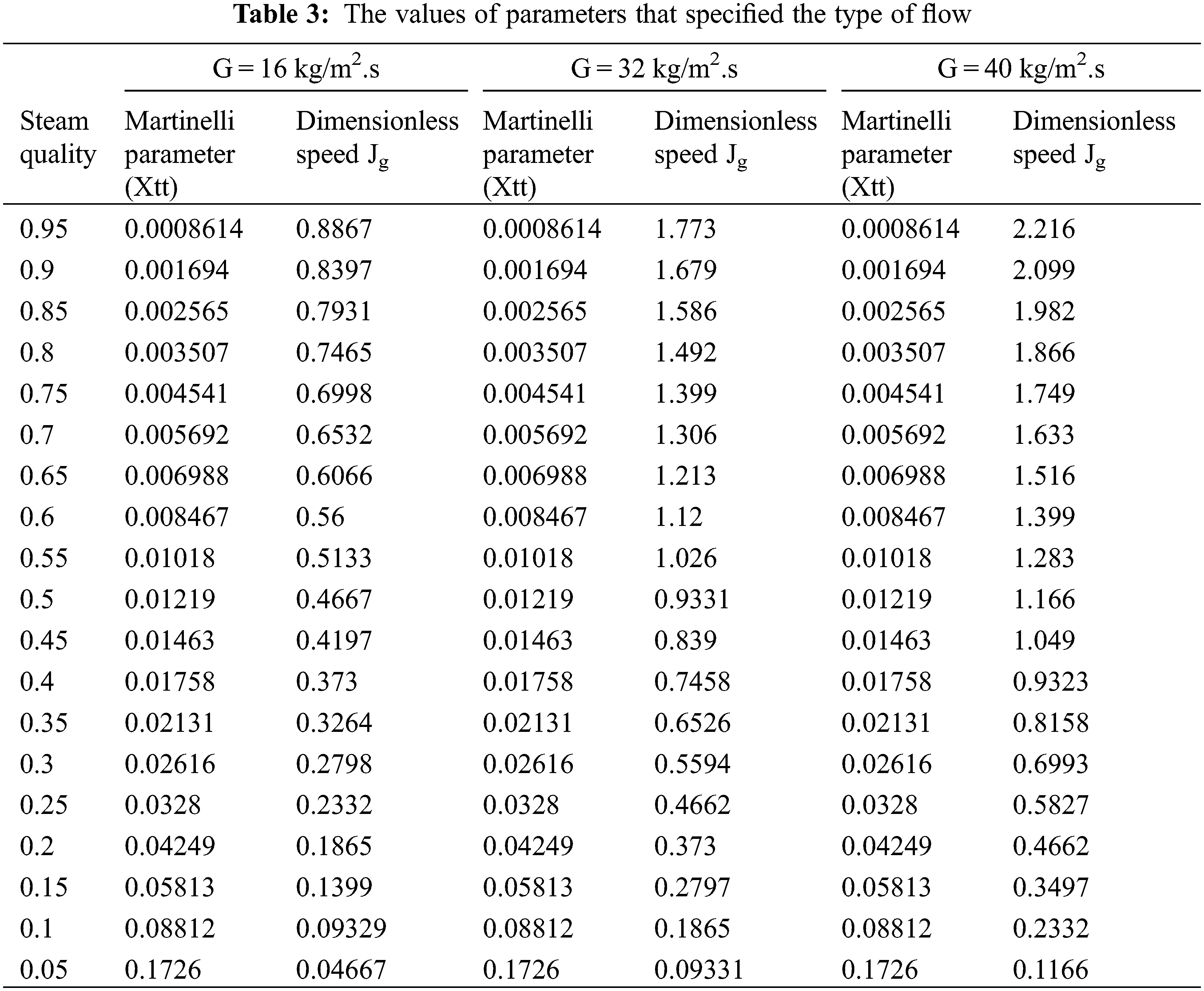
From Table 3, it can be observed that the values of the Martinelli parameter have lower quantities than the limited value (as in Table 1) for mass fluxes of G = 16, 32 and 40 kg/m2.s, which reflects the high volume of vapor along sections of the flattened tube. This indicates that the flow pattern inside the tube is either wavy-stratified flow or annular flow depending on the other factor, which is the dimensionless speed. At G = 16 kg/m2.s, the values of dimensionless speed are less than the limited value of wavy-stratified flow; subsequently, the structure of the flow will be wavy-stratified, which means that the gravity force has been dominated instead of shear stress. In contrast, the structure of the flow begins at annular flow at mass flux G = 32 kg/m2.s, at steam quality equal to 0.95 to 0.85 corresponding to the dimensionless speed, which is higher than the limited value by more than 1.5, and then converts into wavy-stratified flow at steam quality that equals 0.8 to 0.05. When increasing the mass flux to G = 40 kg/m2.s, the annular flow structure will take a wider range relative to the length of the condensation tube because the shear force (momentum) is higher than that at mass flux G = 32 kg/m2.s, and then the flow has been converted to wavy-stratified flow at a steam quality equal to 0.6 due to the limited value of dimensionless speed parameter in Table 1, whereas a result of the decreasing in the momentum force of the steam that flows compared to the force of gravity for it.
4.2 Impact of Mass Velocity on the Heat Transfer Model
Fig. 4 presents the heat transfer coefficient vs. steam quality at the range of mass velocity from 20 to 40 kg/m2.s. The results in the figure can be divided into two categories, at mass velocity 20–24 kg/m2.s and correspond to the values of Eqs. (2) and (3); the flow structure criterion is wavy-stratified while with increasing mass velocity from 28 to 40 kg/m2.s the flow pattern consists of two regions, the annular and wavy–stratified flow. The position of conversion of flow pattern for each mass velocity occurs at a different steam qualities, which depends on the forces that to be dominated (shear force or gravity force), so at mass velocity G = 28 kg/m2.s, the point of the conversion of the flow structure takes place at a steam quality that equals 0.9, while at mass velocity G = 40 kg/m2.s, the flow pattern started as annular flow and changed to wavy-stratified flow at steam quality equal to 0.6. From the same figure, the heat transfer coefficient increases when the mass velocity increases from 20 to 24 kg/m2.s at the same steam quality with a wavy-stratified flow which is determined according to Eqs. (2) and (3). The stratified wavy flow structure can be observed which includes film-wise condensation in the upper part of the steam condensation cross-section tube and force convective condensation in the lower part of the steam condensation cross-section tube, this happens as a result of an increase in the mass flow rates, which has two effects on the heat transfer model (heat transfer coefficient), which leads to an increase in the velocity of the steam that raises the shear force between liquid condensate and steam subsequently minimizing the thickness of condensate film, also increasing the momentum that will transfer from steam to condensate film. At mass velocity increase to G = 28 kg/m2.s the heat transfer coefficient is degraded from the beginning where the steam quality ranges between 1 and 0.9 because the structure of the flow is an annular flow that depends on the limited values of Eqs. (2) and (3) and hence, converted to wavy-stratified flow. For mass velocity rates ranging from 32 to 40 kg/m2.s the flow structure begins an annular type with a spanning of steam quality from 1 to 0.8 for G = 32 kg/m2.s, while the annular flow begins from steam quality that equals 1 to 0.6 for G = 40 kg/m2.s, then transform to the wavy-stratified flow. This structure of flow indicates degradation in the rate of heat transfer since the liquid film acts as a barrier for the transfer of heat from the vapor (steam); after that, the flow pattern turns to stratified wavy flow, which is characterized by a high heat transfer rate compared to the annular flow pattern. Therefore, it is necessary for the researchers and engineers who design these systems to ensure that the convenient flow pattern includes the highest heat transfer rate and the lowest pressure loss.
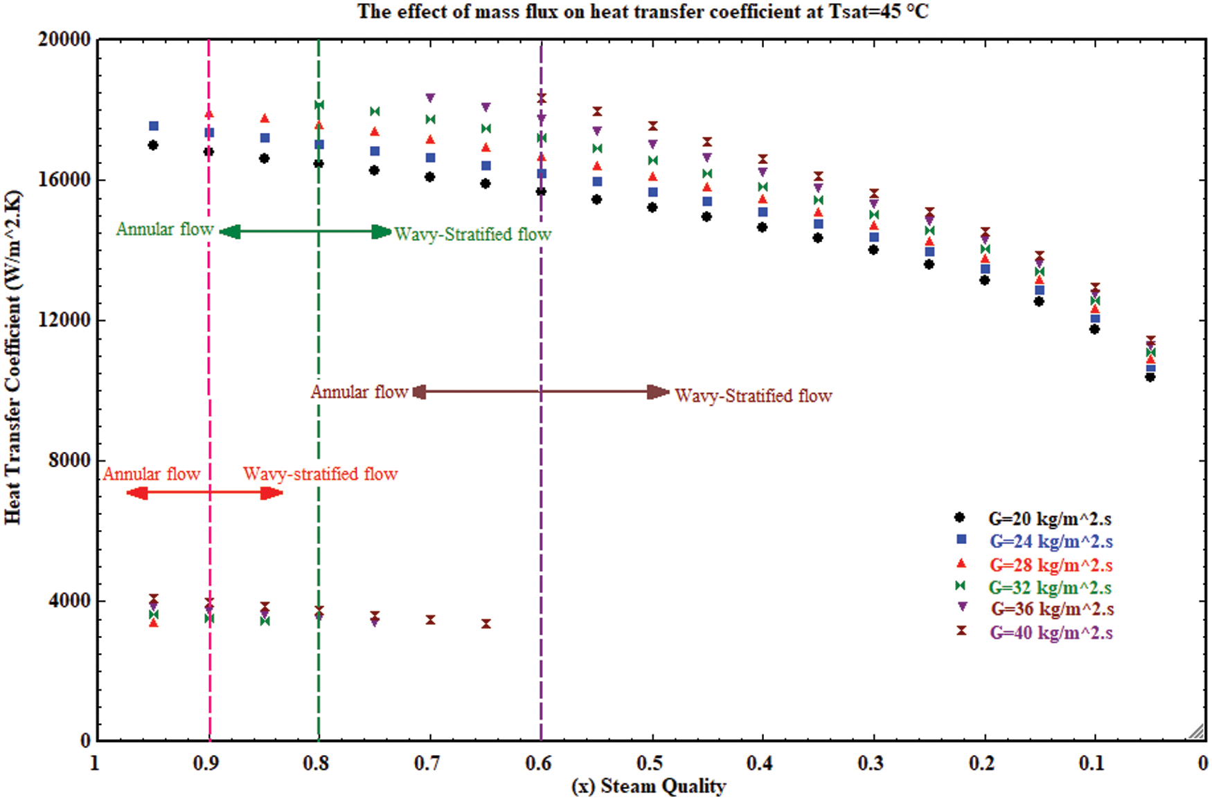
Figure 4: The impact of mass flow rate on heat transfer model
4.3 Impact of Saturated Steam Temperature on Heat Transfer Model
Figs. 5 and 6 present the heat transfer coefficient variation vs. the steam quality at different steam saturated temperatures for mass velocity G = 20 kg/m2 and G = 40 kg/m2.s. Fig. 5 that characterized by a wavy-stratified flow pattern when mass velocity G = 20 kg/m2.s while Fig. 6 shows that the structure of the flow pattern is an annular flow, which then converts to wavy-stratified flow. Generally, there is no significant effect for the saturated steam temperature on the structure of the flow pattern, as shown in Figs. 5 and 6. Hence, with the increase of the saturated steam temperature then, the variation of Martinelli parameter and dimensionless speed did not exceed the limited values as mentioned in Table 1 that will change the structure of the two-phase flow through the condensation process inside the flattened tube. When the mass velocity has a certain amount, the only density of steam and water condensate, which affects the Martinelli parameter and dimensionless speed when increasing the saturated temperature (Eqs. (2) and (3)) which, have less impact compared to the steam mass velocity. Thus the steam mass velocity has a vital impact, which more than the saturated temperature on the structure of the two-phase through the condensation process. Also, from Figs. 5 and 6, it can be observed that the heat transfer coefficient is degraded at the steam quality that equals 0.2–0.05 for the two flow pattern structures with the wavy-stratified flow and annular wavy-stratified flow.
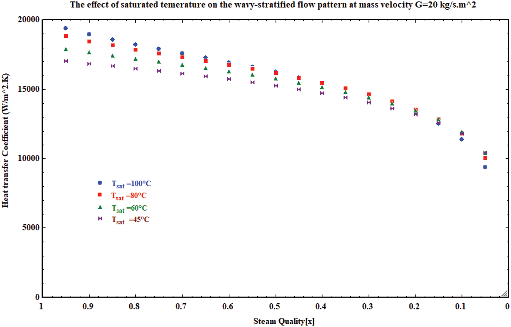
Figure 5: The impact of saturated temperature on the heat transfer model for wavy stratified flow
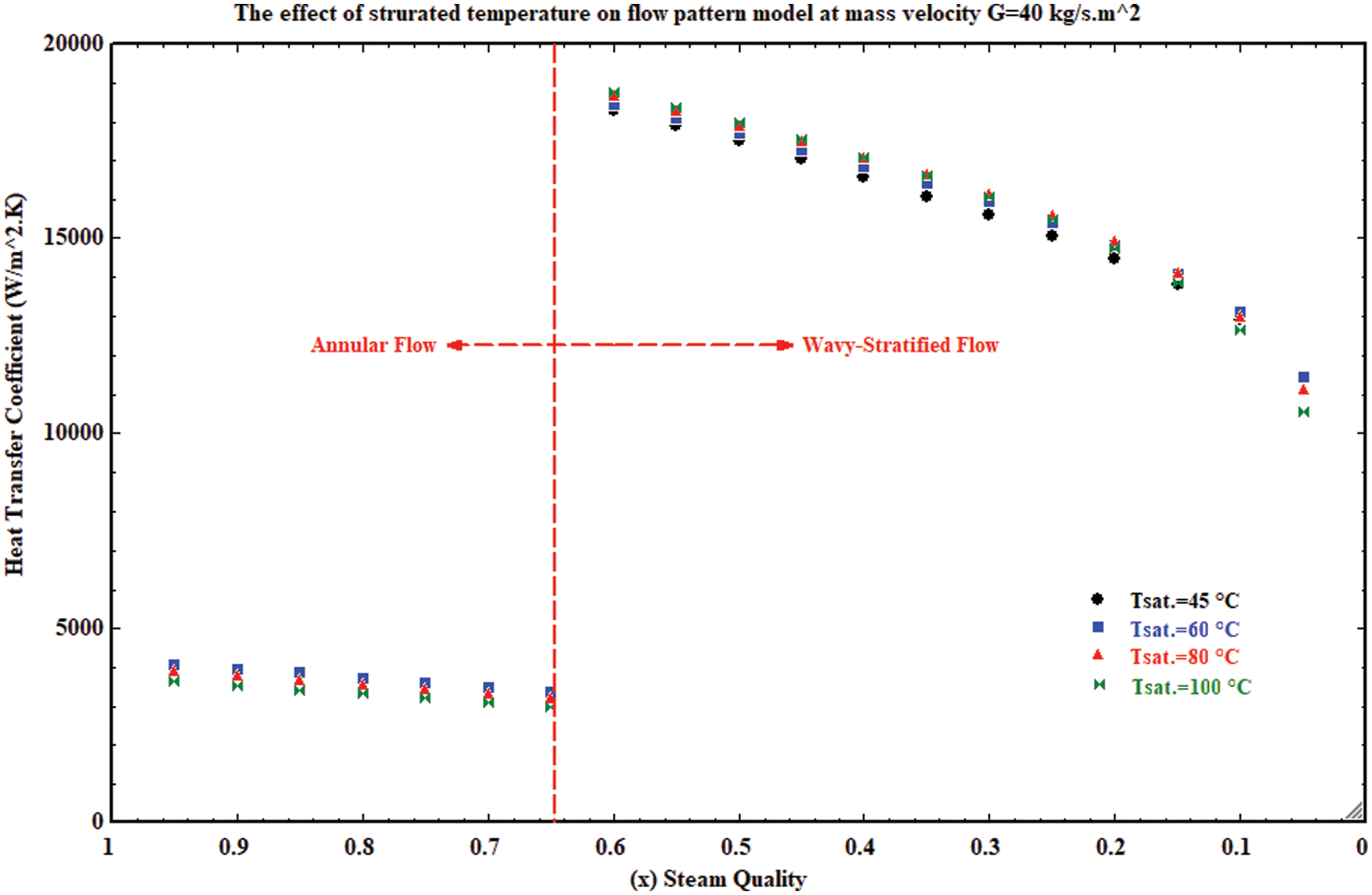
Figure 6: The impact of saturated temperature on the heat transfer model for annular-wavy stratified flow
Indeed, the outcome of condensation, which is a result of phase change from vapor to liquid influenced the momentum force at a range of steam quality, which can help to provide an effective database for the condensation system enhancement and heat transfer rate.
A mathematical model has been adopted to investigate the condensation phenomena inside a horizontal flattened tube. The parameters of steam quality, mass velocity and saturated temperature are used to predict the structure of the two-phase flow and its effect on the heat transfer rate, so, the following can be concluded:
1- The two-phase flow pattern has a significant impact on the heat transfer rate, at mass velocity range from 28–40 kg/m2.s, there are degradations in the heat rate because the flow pattern begins as an annular flow and then it is converted to wavy stratified flow while at mass velocity 20–24 kg/m2.s it started as wavy-stratified flow according to the limited criteria.
2- The mass velocity has an impact on the forces that control the structure of the two-phase flow. When mass velocity ranges in 20–24 kg/m2.s the gravitation force is the dominant force, but at mass velocity range of 28–40 kg/m2.s, the shear force is the dominant force at the beginning of the flow while converting to the gravitation force as a dominate force during the decrease in the momentum of the flow.
3- The saturated temperature has no significant impact on the structure of the two-phase during the flow of condensation. In contrast, the heat transfer coefficient increases with the increase of the saturated steam temperature along the condensation process inside the flattened horizontal tube.
4- The heat transfer coefficient is degraded at steam quality that ranges from x = 0.2 to x = 0.05 for mass velocity range of 20–40 kg/m2.s whether the structure of the two-phase had begun as a wavy-stratified flow or annular wavy-stratified flow.
Acknowledgement: The authors would like to thank Mustansiriyah University (https://www.uomustansiriyah.edu.iq) Baghdad, Iraq, for its present work.
Funding Statement: The authors received no specific funding for this study.
Conflicts of Interest: The authors declare that they have no conflicts of interest to report regarding the present study.
1. Abadi, S. M. A. N. R., Davies, W. A., Hrnjak, P., Meyer, J. P. (2019). Numerical study of steam condensation inside a long inclined flattened channel. International Journal of Heat and Mass Transfer, 134, 450–467. DOI 10.1016/j.ijheatmasstransfer.2019.01.063. [Google Scholar] [CrossRef]
2. Wang, Y., Mu, X., Shen, S., Zhang, W. (2017). Heat transfer characteristics of steam condensation flow in vacuum horizontal tube. International Journal of Heat and Mass Transfer, 108, 128–135. DOI 10.1016/j.ijheatmasstransfer.2016.12.006. [Google Scholar] [CrossRef]
3. Lips, S., Meyer, J. P. (2012). Stratified flow model for convective condensation in an inclined tube. Intertional Journal of Heat and Fluid Flow, 36, 83–91. DOI 10.1016/j.ijheatfluidflow.2012.03.005. [Google Scholar] [CrossRef]
4. Shen, D., Gui, C., Xia, J., Xue, S. (2020). Experimental analysis of the performances of unit refrigeration systems based on parallel compressors with consideration of the volumetric and isentropic efficiency. Fluid Dynamics & Materials Processing, 16, 489–500. DOI 10.32604/fdmp.2020.08969. [Google Scholar] [CrossRef]
5. Chato, J. C. (1960). Laminar condensation inside horizontal and inclined tubes. Journal of ASHARE, 4, 52–60. [Google Scholar]
6. Carey, V. P. (1992). Liquid-vapor phase change phenomena: An introduction to the thermophysics of vaporization and condensation processes in heat transfer equipment. New York: Hemisphere Publishing. [Google Scholar]
7. Bejan, A., Kraus, A. D. (2003). Heat transfer handbook, vol. 1. John Wiley & Sons, Inc. USA. [Google Scholar]
8. Dobson, M. K. (1994). Heat transfer and flow regimes during condensation in horizontal tubes (Ph.D. Thesis). University of Illinois, USA. [Google Scholar]
9. Baker, O. (1954). Design of pipelines for simultaneous flow of oil and gas flow of oil and gas. Oil and Gas Journal, 7, 185–195. DOI 10.2118/323-G. [Google Scholar] [CrossRef]
10. Mandhane, J. M., Gregory, G. A., Aziz, K. (1974). A flow pattern map for gas-liquid flow in horizontal pipes. International Journal of Multiphase Flow, 1, 537–553. DOI 10.1016/0301-9322(74)90006-8. [Google Scholar] [CrossRef]
11. Taitel, Y., Dukler, A. E. (1976). A model for predicting flow regime transitions in horizontal and near horizontal gas-liquid flow. AIChE Journal, 22, 47–55. DOI 10.1002/AIC.690220105. [Google Scholar] [CrossRef]
12. Soliman, H. M. (1986). The mist-annular transition during condensation and its influence on the heat transfer mechanism. International Journal of Multiphase Flow, 12, 277–288. DOI 10.1016/0301-9322(86)90030-3. [Google Scholar] [CrossRef]
13. Dobson, M. K., Chato, J. C. (1998). Condensation in smooth horizontal tubes. Journal of Heat Transfer, 1998, 120, 193–213. DOI 10.1115/1.2830043. [Google Scholar] [CrossRef]
14. El Hajal, J., Thome, J. R., Cavallini, A. (2003). Condensation in horizontal tubes, part 1: Two-phase flow pattern map. International Journal of Heat and Mass Transfer, 46, 3349–3363. DOI 10.1016/S0017-9310(03)00139-X. [Google Scholar] [CrossRef]
15. Kattan, N., Thome, J. R., Favrat, D. (1998). Flow boiling in horizontal tubes: Part 3–Development of a new heat transfer model based on flow pattern. Journal of Heat Transfer, 120, 156–165. DOI 10.1115/1.2830039. [Google Scholar] [CrossRef]
16. Kattan, N., Thome, J. R., Favrat, D. (1998). Flow boiling in horizontal tubes: Part 1–Development of a diabatic two-phase flow pattern map. Journal of Heat Transfer, 120, 140–147. DOI 10.1115/1.2830037. [Google Scholar] [CrossRef]
17. Shah, M. M. (1979). A general correlation for heat transfer during film condensation inside pipes. International Journal of Heat and Mass Transfer, 22, 547–556. DOI 10.1016/0017-9310(79)90058-9. [Google Scholar] [CrossRef]
18. Shah, M. M. (2009). An improved and extended general correlation for heat transfer during condensation in plain tubes. HVAC&R Research, 15, 889–913. DOI 10.1080/10789669.2009.10390871. [Google Scholar] [CrossRef]
19. Shah, M. M. (2013). General correlation for heat transfer during condensation in plain tubes: Further development and verification. ASHRAE Transactions, 119, 3–11. [Google Scholar]
20. Shah, M. M. (2016). Prediction of heat transfer during condensation in inclined plain tubes. Applied Thermal Engineering, 94, 82–89. DOI 10.1016/j.applthermaleng.2015.10.122. [Google Scholar] [CrossRef]
21. Mahdi, L. A. A., Kassim, M. S., Kamil, M. G. M. (2020). Predicting of steam condensation heat transfer coefficient in horizontal flattened tube. Journal of Engineering and Sustainable Development, 24, 115–126. DOI 10.31272/jeasd. [Google Scholar] [CrossRef]
22. Ahn, T., Kang, J., Bae, B., Jeong, J. J., Yun, B. (2019). Steam condensation in horizontal and inclined tubes under stratified flow conditions. International Journal of Heat and Mass Transfer, 2019, (141), 71–87. DOI 10.1016/j.ijheatmasstransfer.2019.06.056. [Google Scholar] [CrossRef]
23. Sereda, V., Rifert, V., Gorin, V., Baraniuk, O., Barabash, P. (2021). Heat transfer during film condensation inside horizontal tubes in stratified phase flow. Heat and Mass Transfer, 57, 251–267. DOI 10.1007/s00231-020-02946-2. [Google Scholar] [CrossRef]
24. Abdulkareem, L. A., Musa, V. A., Mahmood, R. A., Hasso, E. A. (2021). Experimental investigation of two-phase flow patterns in a vertical to horizontal bend pipe using wire-mesh sensor. Review of Chemistry, 71, 18–33. DOI 10.37358/RC.20.12.8383. [Google Scholar] [CrossRef]
25. Rosson, H. F. (1975). Heat transfer during condensation inside a horizontal tube (Ph.D. Thesis). Rice University. [Google Scholar]
26. Breber, G., Palen, J. W., Taborek, J. (1980). Prediction of horizontal tubeside condensation of pure components using flow regime criteria. Journal of Heat Transfer, 102, 471–476. DOI 10.1115/1.3244325. [Google Scholar] [CrossRef]
27. Mahmood, R. A., Buttsworth, D., Malpress, R., Sharifian-Barforoush, A. (2021). CFD numerical and experimental investigation of two-phase flow development after an expansion device in a horizontal pipe. Journal of Thermal Engineering, 7, 307–323. DOI 10.15282/ijame.16.2.2019.18.0505. [Google Scholar] [CrossRef]
28. Mahmood, R. A., Buttsworth, D., Malpress, R. (2019). Computational and experimental investigation of the vertical flash tank separator. Part 1: Effect of parameters on separation efficiency. International Journal of Air-Conditioning and Refrigeration, 27, 1950005. DOI 10.1142/S2010132519500056. [Google Scholar] [CrossRef]
29. Mahmood, R. A., Buttsworth, D., Malpress, R. (2019). Computational and experimental investigation of using an extractor in the vertical gravitational flash tank separator. International Journal of Automotive and Mechanical Engineering, 16, 6706–6722. DOI 10.15282/ijame.16.2.2019.18.0505. [Google Scholar] [CrossRef]
 | This work is licensed under a Creative Commons Attribution 4.0 International License, which permits unrestricted use, distribution, and reproduction in any medium, provided the original work is properly cited. |