| Fluid Dynamics & Materials Processing |
DOI: 10.32604/fdmp.2022.019787
ARTICLE
Performance Analysis of an Organic Rankine Cycle with a Preheated Ejector
1Tianjin Key Lab of Refrigeration Technology, Tianjin University of Commerce, Tianjin, 300134, China
2Institute of Food Science and Technology, Chinese Academy of Agricultural Sciences, National Risk Assessment Laboratory of Agro-Products Processing Quality and Safety, Ministry of Agriculture and Rural Affairs, Beijing, 100193, China
3Tianjin Tengsheng Technology Co., Ltd., Tianjin, 300380, China
*Corresponding Authors: Kaiyong Hu. Email: hky422@tjcu.edu.cn; Dequan Zhang. Email: dequan_zhang0118@126.com
Received: 15 October 2021; Accepted: 12 January 2022
Abstract: The so-called organic Rankine cycle (ORC) is an effective technology allowing heat recovery from lower temperature sources. In the present study, to improve its thermal efficiency, a preheated ejector using exhaust steam coming from the expander is integrated in the cycle (EPORC). Considering net power output, pump power, and thermal efficiency, the proposed system is compared with the basic ORC. The influence of the ejector ratio (ER) of the preheated ejector on the system performances is also investigated. Results show that the net power output of the EPORC is higher than that of the basic ORC due to the decreasing pump power. Under given working conditions, the average thermal efficiency of EPORC is 29% higher than that of ORC. The ER has a great impact on the performance of EPORC by adjusting the working fluid fed to the pump, leading to significant variations of the pump work Moreover, the ER has a remarkable effect on the working fluid temperature lift (TL) at the evaporator inlet, thus reducing the evaporator heat load. According to the results, the thermal efficiency of EPORC increases by 30%, when the ER increases from 0.05 to 0.4.
Keywords: Ejector preheat organic Rankine cycle (EPORC); heat recovery; ejector; power output
In the last two decades, the problems of fossil fuel shortages, environmental pollution, and carbon emissions caused by growing industrialization have become more and more prominent, and the exploration and utilization of waste and renewable energy have drawn a burgeoning number of attentions from both governments and several organizations. In order to gradually reduce the use of fossil fuels, it is expected that more electricity should be generated using renewable energy. A survey from the IEA indicated that electricity generation from renewables is expected to triple between 2010 and 2035, reaching 31% of total generation [1]. In addition, survey data indicated that low-grade heat accounts for 60% of the waste heat produced in industrial processes. However, conventional energy conversion technologies have low thermal efficiencies when they are used to explore low-grade heat [2]. ORC (organic Rankine cycle) is an effective technology and is considered to be one of the practical methods for converting low-grade heat to power, being progressively adopted for its simplicity, reliability, and flexibility [3,4].
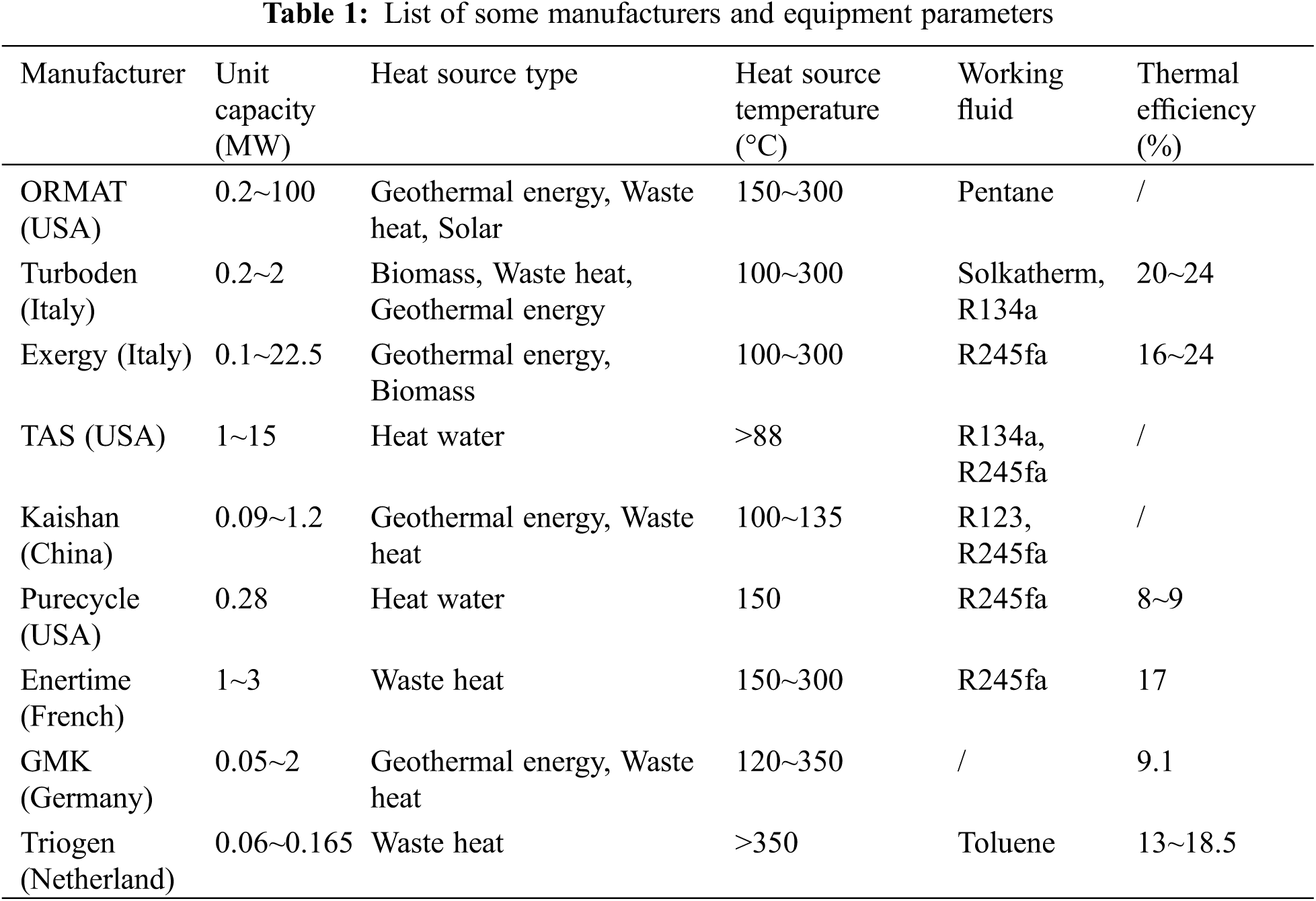
Commercial applications for different markets have been widely distributed in Europe and the US. Until January 21st, 2016, the total installed capacity of the ORC system was 2749.1 MWe in 563 power plants, and the new capacity planned is 523.6 MWe in 75 plants. In terms of market share, geothermal power plants contribute to 76.5% of all ORC installed capacity, and the US has the largest installed capacity. Some of the ORC equipment parameters are listed in Table 1 [5].
Because of the increased focus on low and medium temperature heat recovery, a large number of ORC studies have been completed since 2000 in order to improve ORC performance and maximize electricity production [6]. The following topics are primarily the focus of research: the selection of pure or zeotropic working fluids [7–9], system optimization [10,11], component modification [12,13], various thermodynamic cycles (basic ORC cycle, trans-supercritical cycle, regenerative cycle, and combined cycle) [14–16], and economic analysis [17–19].
In ORC system, the working fluid collects heat from the evaporator’s heat source and releases it to the condenser’s heat sink. The temperature of the superheated vapor at the expander outlet is higher than that at the evaporator inlet. Some researchers proposed an ORC system with an internal heat exchanger (IHE) to recover the discharged heat that would otherwise be released in the condenser.
Li et al. [20] carried out an investigation on ORC integrated with IHE with different working fluids, showing that IHE has an advantage in ORC system using mixture working fluids. Yari [21] compared the regenerative ORC with other types of geothermal power systems. Moreover, Yari investigated the regenerative ORC using different working fluids, including isobutene, isopentane, R113, and R123. Desai et al. [22] found that a 16.5% increase in thermal efficiency was obtained for 16 working fluids employing regenerative ORC. Li et al. [23] experiment investigated regenerative ORC and basic ORC, showing that regenerative ORC has a 1.83% higher thermal efficiency than that of basic ORC.
To improve the efficiency of the ORC system, some researchers have tried to utilize the discharged heat from the expander to reduce the power consumed by the pump. The ejector preheater is a simple device in which high-pressure liquid and low-pressure gas mix and exchange heat directly. Li et al. [24] investigated ORC with an ejector, indicating that the ejector can increase the power output capacity. Zhang et al. [25] proposed a novel ORC system which combines the basic ORC system and an ejector heat pump. An ejector is installed at the inlet of the expander to increase the total heat by using the ejection ability caused by the high-pressure fluid from the pump. Results show that the novel combined system can increase the maximum net output and heat recovery ability by 10.78% and 19.04%, respectively. Feng et al. [26] added a regenerator to recover the extra exhaust heat from the expander outlet. A comparison between the basic and regenerative ORC was investigated. According to research, the basic ORC utilizes heat sources at a higher temperature than the regenerative ORC. The maximum thermal efficiency of regenerative ORC is 5.5%, which is 25.5% higher than the maximum thermal efficiency of basic ORC, which is 4.1%. Chen et al. [27] presented and compared a modified ORC system with a vapor-liquid ejector to the basic ORC. According to the results, the modified system has a higher thermal efficiency.
In this paper, a novel ORC system integrated with an ejector preheater, called EPORC, is proposed. In this system, an ejector is selected as a mixer, where part of the working fluid from the expander is used to preheat the working fluid from the pump directly. The ejector leads to three advantages: (1) the average evaporating temperature is increased due to the fact that the working fluid is preheated to saturation temperature or near saturation temperature; (2) the heat load in the evaporator is reduced for recovering part of the discharged heat from the expander; and (3) the pump work is reduced since part of the working fluid is fed to the ejector directly without running though the pump. A detailed thermodynamic analysis is carried out in order to present the characteristics of the proposed system.
2 Principle and Thermodynamic Models of the EPORC System
The schematic of the EPORC system is shown in Fig. 1. The EPORC system mainly consists of evaporator, expander, condenser, storage tank, pump, and ejector preheater. The pump pressurizes the low-boiling working fluid into the ejector preheater where the high temperature vapor mixes with the low temperature liquid working fluid. The fully mixed working fluid flows into the evaporator where the working fluid gains heat and vaporizes. The high-pressure vapor flows into the expander where the enthalpy is converted into work. The low-pressure vapor from the expander is divided into two parts. One part of the vapor flows into the condenser where it is liquefied by the cooling water and led to the liquid reservoir. The liquefied working fluid is then pumped to the ejector preheater, which induces the other part of the vapor from the expander to the ejector preheater. In the ejector preheater, the vapor releases heat to the liquid in a rapid condensation process. Two working fluids in different states are fully mixed and become single-phase. Finally, the liquid working fluid flows back to the evaporator, and a closed cycle is formed.
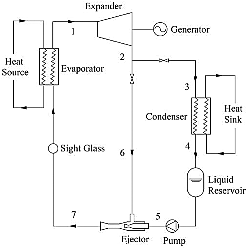
Figure 1: Schematic of the EPORC system
The liquid-vapor ejector preheater plays an important role in the EPORC system, although it has a simple structure. Its structure and working principle are shown in Fig. 2. As shown in Fig. 2, the high-pressure liquid changes from subsonic to supersonic, forming a low-pressure region in the suction chamber of the ejector preheater (a–c). The low-pressure vapor is entrained into the mixing chamber by the pressure difference (b–c). The liquid and vapor go through a quick condensation process with direct contact in the mixing chamber forepart where direct contact heat transfer occurs (c–d). The mixing flow may have mixing layers with shockwaves because the speed of the mixing flow excesses the sonic speed in the constant area section of the mixing chamber (d–e). Besides, in the mixing chamber, the two different flows are completely mixed and the vapor is condensed into liquid. Finally, the fluid is decelerated and recompressed in the diffuser.
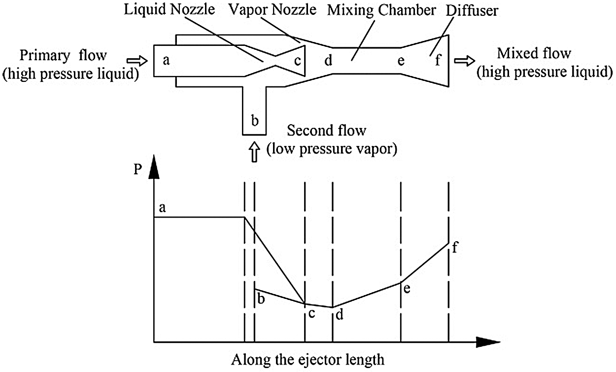
Figure 2: Principle of ejector operation
The thermodynamic processes of the EPORC system are presented in the T-S diagram shown in Fig. 3.
The flow mechanism in the ejector is complex. It is not easy to establish a model to simulate the detailed flow process in the system. For simplicity, the following hypotheses are adopted for the system modeling:
(1) Every component operates at a steady state.
(2) The efficiencies of the expander and pump are set as constants.
(3) The vapor and liquid exchange heat completely in the ejector, and the flow in the ejector is one dimension.
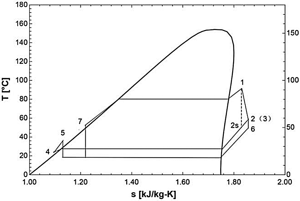
Figure 3: T-S diagram of EPORC
Considering the above hypotheses, the mathematical models of the EPORC system are defined as follows:
The ejector ratio (ER) is defined as below:
where, mwf,sec and mwf,pri are the mass flow rates of the primary flow and second flow of the ejector, respectively.
The total heat input in the evaporator is:
where, mwf , h1 and h7 are the mass flow rate of the working fluid, the evaporator outlet enthalpy and the evaporator inlet enthalpy, respectively.
The power generated from the expander is:
where, h2,
The total heat released to the heat sink is:
where, h4 is the condenser outlet enthalpy.
The power consumed by the pump is:
where, h5 and
The process in the ejector is:
where, h6 is the second flow enthalpy of the ejector.
The net power output is:
The thermal efficiency is:
The temperature lift (TL) is expressed as the difference between the ejector outlet temperature and the primary flow temperature. It denotes the ability of the ejector preheater to preheat the working fluid.
where, T7 and T5 are the ejector outlet temperature and the primary flow temperature of the ejector, respectively.
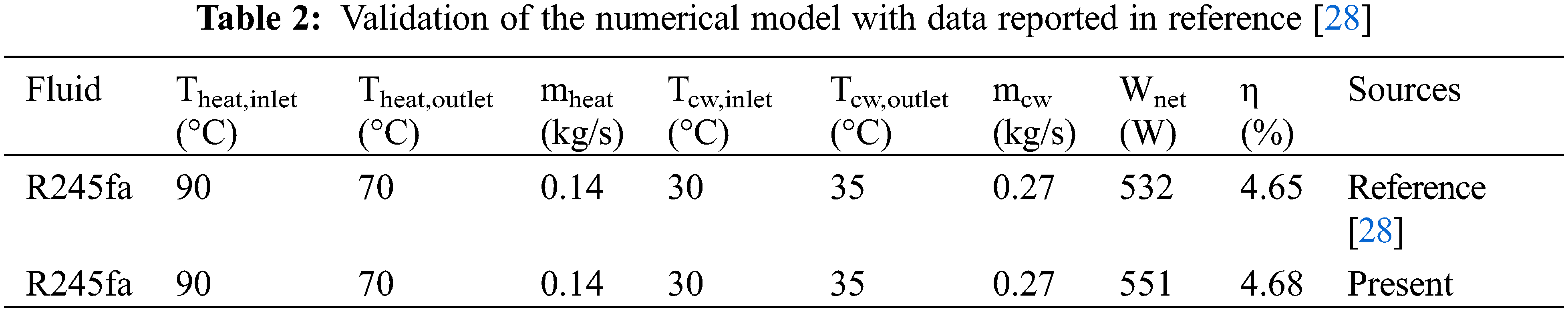
The basic ORC system numerical model is validated using previously published data from reference [28], with the same heat source and heat sink and R245fa as the working fluid. The following parameters are set for verification calculation: heat source inlet (Theat,inlet) and outlet (Theat,outlet) temperatures are set as 90 °C and 70°C; the mass flow of the heat source medium (mheat) is 0.14 kg/s; the cooling water inlet (Tcw,inlet) and outlet (Tcw,outlet) temperatures are 30°C and 35°C, respectively; the mass flow of the cooling water (mcw) is 0.27 kg/s. The numerical results are shown in Table 2. The absolute difference in the net power output is 19 W, with a relative difference of 3.6%. Moreover, the relative difference in the thermal efficiency is 0.65%, showing that the numerical calculation accuracy of the present model is reliable.
The performances of ORC and EPORC are compared under the same operating conditions with R245fa as the working fluid. In order to highlight the characteristics of the EPORC system, the influences of the pump isentropic efficiency, evaporating temperature, and condensing temperature on the performances of these two systems are studied.
Fig. 4 presents the effect of pump isentropic efficiency on system performance. Obviously, EPORC and ORC have the same Wgen because of the same working conditions for the expander. As ηp increases, Wp decreases as expected. In addition, EPORC has a little lower value than ORC since part of the uncondensed working fluid from the expander is led to the ejector preheater without flowing into the pump. Therefore, EPORC can produce more net power than ORC. Fig. 4b indicated that ηsys increases with the increasing of ηp which can be understood easily. Moreover, the ηsys of EPORC is higher than ORC, which can be explained using Eq. (7) . EPORC has a higher Wnet than ORC, which has been explained before. Furthermore, compared with ORC, EPORC has a lower heat load in the evaporator as the ejector acts as a regenerator, preheating the working fluid before the evaporator. As seen in Fig. 4b, when ηp is 70%, theηsys of EPORC (6.96%) is 29% higher than that of ORC (5.38%).
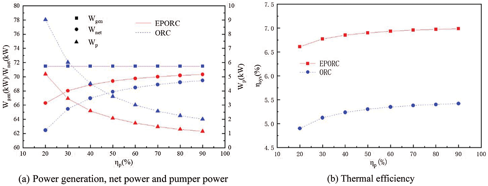
Figure 4: Effect of pump isentropic efficiency on system performance
Fig. 5 depicts the power generation (Wgen), the net power (Wnet), the pump power (Wp), and the system thermal efficiency (ηsys) vs. the evaporating temperature (Te) when ηp = 75%. Clearly, Wgen, Wnet, and Wp for both EPORC and ORC increase first, then decrease with Te increasing, and every parameter has a maximum value. EPORC has a lower Wp than ORC because part of the working fluid does not flow into the pump. In addition, Wnet of EPORC is slightly higher than that of ORC. It can be seen from Fig. 5b that the higher evaporating temperature is, the higher thermal efficiency can be obtained by both EPORC and ORC. As Te increases from 55°C to 83°C, ηsys of EPORC and ORC increase from 4.43% to 8.77% and 3.39% to 6.82%, respectively. At the given evaporating temperature, the ηsys of EPORC is constantly higher than that of ORC.
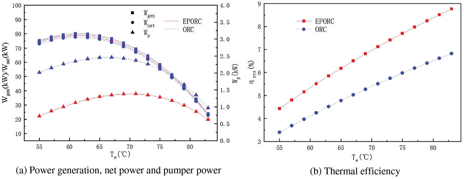
Figure 5: Effect of evaporator temperature on system performance
Fig. 6 displays the power generation (Wgen), the net power (Wnet), the pump work (Wp), and the system thermal efficiency (ηsys) with respect to the condensing temperature when ηp = 75%. Wgen and Wnet for both EPORC and ORC decrease with the increase of condensing temperature. Because the corresponding pressure of the working fluid will increase with the increase of condensing temperature, so the inlet and outlet enthalpy drop of the expander will decrease, leading the decrease of the power generation. The variation of the condensing temperature has a slightly effect on the pump work (Wp). According to the calculation method, it is known that the change of condensing temperature has no effect on the heat absorption. As a result, as shown in Fig. 6b, the thermal efficiency decreases while the condensing temperature gradually rises.
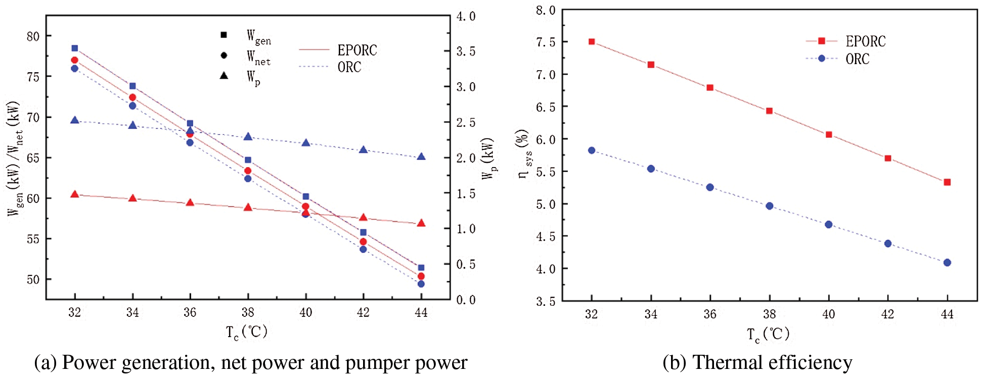
Figure 6: Effect of condenser temperature on system performance
3.2 Effect of the Ejector Ratio
The ejector preheater ratio (ER) represents the performance of the ejector. Fig. 7 illustrates the variations of the EPORC performance with ER using working fluids R245fa and R123. As the front and back conditions and the expander isentropic efficiency are set, it is easy to understand that Wgen is unchanged. Based on Eqs. (4) and (6), an increase in ER with the unchanged working fluid leads to a decrease of the working fluid flowing through the working pump, which means that less pump work is needed. Although more second flow in the ejector needs to be pressurized, the increased power consumed by the ejector is less than the decrease in pump work. Therefore, Wnet increases with the increase of ER.
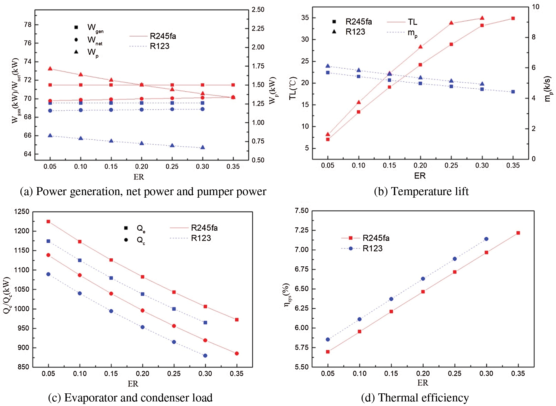
Figure 7: Effect of entrainment ratio (ER) on system performance
Temperature lift (TL) is an important indicator of the ejector preheater, showing the preheating effect of working fluid flowing into the evaporator. According to Fig. 7b, increasing ER can effectively increase TL, and the rise of TL has a maximum value. This can be explained in two ways: (1) a larger ER indicates that more working fluid from the expander is fed into the ejector to preheat the working fluid from the pump, and (2) the working fluid at the evaporator inlet has a saturation temperature, which is the maximum value that the working fluid can reach.
Fig. 7c indicates the effect of ER on the evaporator and condenser loads. Obviously, both the evaporator and condenser load decrease as ER increases. Considering that the power generation keeps constant and the net power increases as shown in Fig. 7a, it is easy to draw the conclusion that increasing ER can improve the system efficiency, which is shown in Fig. 7d.
In this paper, a novel ORC system integrated with an ejector preheater, called EPORC, is proposed. It is compared to the basic ORC system, considering the effect of pump efficiency and operating conditions. Moreover, the effects of ER on the system performance with two different working fluids are studied. The main conclusions drawn from the present study can be summarized as follows:
(1) Compared with the basic ORC system, EPORC has less pump power, resulting in higher net power generation.
(2) Under given operating conditions, EPORC has higher thermal efficiency than the basic ORC system. When the pump efficiency is 70%, the thermal efficiency of EPORC (6.96%) is 29% higher than that of basic ORC (5.38%).
(3) The preheating effect of the ejector is very good. Increasing ER can effectively improve the TL value. However, there is a maximum TL for the ejector, which is influenced by the saturation temperature corresponding to the saturation pressure in the evaporator. What is more, the thermal efficiency of EPORC increases by 30%, when the ejector ratio increases from 0.05 to 0.4.
Funding Statement: This work was supported by the National Risk Assessment Laboratory of Agro-products Processing Quality and Safety, Ministry of Agriculture and Rural Affairs (S2020KFKT-06).
Conflicts of Interest: The authors declare that they have no conflicts of interest to report regarding the present study.
1. Zhu, J., Hu, K., Lu, X., Huang, X., Liu, K. et al. (2015). A review of geothermal energy resources, development, and applications in China: Current status and prospects. Energy, 93(5), 466–483. DOI 10.1016/j.energy.2015.08.098. [Google Scholar] [CrossRef]
2. Loni, R., Najafi, G., Bellos, E., Rajaee, F., Said, Z. et al. (2020). A review of industrial waste heat recovery system for power generation with Organic Rankine Cycle: Recent challenges and future outlook. Journal of Cleaner Production, 287(10), 125070. DOI 10.1016/j.jclepro.2020.125070. [Google Scholar] [CrossRef]
3. Parisa, K., Rad, E. (2022). Optimization of the boiler pressure and working fluid in a binary organic Rankine cycle for different heat sources. Energy, 238, 121671. DOI 10.1016/j.energy.2021.121671. [Google Scholar] [CrossRef]
4. Nondy, J., Gogoi, T. K. (2021). Exergoeconomic investigation and multi-objective optimization of different ORC configurations for waste heat recovery: A comparative study. Energy Conversion and Management, 245(4), 114593. DOI 10.1016/j.enconman.2021.114593. [Google Scholar] [CrossRef]
5. Wang, D., Duan, J., Hu, B., Shen, X. (2015). Status of organic Rankine cycle power generation technology. Energy Conservation Technology, 33, 235–242. [Google Scholar]
6. Imran, M., Haglind, F., Asim, M., Alvi, J. (2018). Recent research trends in organic Rankine cycle technology: A bibliometric approach. Renewable and Sustainable Energy Reviews, 81, 552–562. DOI 10.1016/j.rser.2017.08.028. [Google Scholar] [CrossRef]
7. Frutiger, J., Andreasen, J., Liu, W., Spliethoff, H., Haglind, F. et al. (2016). Working fluid selection for organic Rankine cycles-Impact of uncertainty of fluid properties. Energy, 109, 987–997. DOI 10.1016/j.energy.2016.05.010. [Google Scholar] [CrossRef]
8. Abadi, G. B., Kim, K. C. (2017). Investigation of organic Rankine cycles with zeotropic mixtures as a working fluid: Advantages and issues. Renewable and Sustainable Energy Reviews, 73(6), 1000–1013. DOI 10.1016/j.rser.2017.02.020. [Google Scholar] [CrossRef]
9. Rayegan, R., Tao, Y. (2011). A procedure to select working fluids for Solar Organic Rankine Cycles (ORCs). Renewable Energy, 36(2), 659–670. DOI 10.1016/j.renene.2010.07.010. [Google Scholar] [CrossRef]
10. Świerzewski, M., Kalina, J., Musiał, A. (2021). Techno-economic optimization of ORC system structure, size and working fluid within biomass-fired municipal cogeneration plant retrofitting project. Renewable Energy, 180(2), 281–296. DOI 10.1016/j.renene.2021.08.068. [Google Scholar] [CrossRef]
11. Kim, D., Lee, J., Kim, J., Kim, M., Kim, M. (2017). Parametric study and performance evaluation of an organic Rankine cycle (ORC) system using low-grade heat at temperatures below 80°C. Applied Energy, 189(12), 55–65. DOI 10.1016/j.apenergy.2016.12.026. [Google Scholar] [CrossRef]
12. Jubori, A., Ai, R., Mahmoud, S., Ennil, L., Rahbar, K. (2017). Three dimensional optimization of small-scale axial expander for low temperature heat source driven organic Rankine cycle. Energy Conversion and Management, 133(2), 411–426. DOI 10.1016/j.enconman.2016.10.060. [Google Scholar] [CrossRef]
13. Dong, J., Zhang, X., Wang, J. (2017). Experimental investigation on heat transfer characteristics of plat heat exchanger applied in organic Rankine cycle (ORC). Applied Thermal Engineering, 112, 1137–1152. DOI 10.1016/j.applthermaleng.2016.10.190. [Google Scholar] [CrossRef]
14. Zhang, X., Wu, L., Wang, X., Ju, G. (2016). Comparative study of waste heat steam SRC, ORC and S-ORC power generation systems in medium-low temperature. Applied Thermal Engineering, 106, 1427–1439. DOI 10.1016/j.applthermaleng.2016.06.108. [Google Scholar] [CrossRef]
15. Zhu, J., Hu, K., Zhang, Wei, Lu, X. (2017). A study on generating a map for selection of optimum power generation cycles used for Enhanced Geothermal Systems. Energy, 133(7), 502–512. DOI 10.1016/j.energy.2017.05.130. [Google Scholar] [CrossRef]
16. Yağlı, H., Koç, Y., Kalay, H. (2021). Optimisation and exergy analysis of an organic Rankine cycle (ORC) used as a bottoming cycle in a cogeneration system producing steam and power. Sustainable Energy Technologies and Assessments, 44(10), 100985. DOI 10.1016/j.seta.2020.100985. [Google Scholar] [CrossRef]
17. Tang, Z., Wu, C., Liu, C., Xu, X., Liu, J. (2021). Thermodynamic analysis and comparison of a novel dual-ejector based organic flash combined power and refrigeration cycle driven by the low-grade heat source. Energy Conversion and Management, 239(3), 114205. DOI 10.1016/j.enconman.2021.114205. [Google Scholar] [CrossRef]
18. Muhammad, I., Byung, S., Hyouck, J., Lee, D., Muhammad, U. et al. (2014). Thermo-economic optimization of Regenerative Organic Rankine Cycle for waste heat recovery applications. Energy Conversion and Management, 87, 107–118. DOI 10.1016/j.enconman.2014.06.091. [Google Scholar] [CrossRef]
19. Kolahi, M., Yari, M., Mahmoudi, S., Mohamadkhani, F. (2016). Thermodynamic and economic performance improvement of ORCs through using zeotropic mixtures: case of waste heat recovery in an offshore platform. Case Studies in Thermal Engineering, 8(1), 51–70. DOI 10.1016/j.csite.2016.05.001. [Google Scholar] [CrossRef]
20. Li, W., Feng, X., Yu, L., Xu, J. (2011). Effects of evaporating temperature and internal heat exchanger on organic Rankine cycle. Applied Thermal Engineering, 31(17–18), 4014–4023. DOI 10.1016/j.applthermaleng.2011.08.003. [Google Scholar] [CrossRef]
21. Yari, M. (2011). Exergetic analysis of various types of geothermal power plants. Renewable Energy, 35(1), 112–121. DOI 10.1016/j.renene.2009.07.023. [Google Scholar] [CrossRef]
22. Desai, N., Bandyopadhyay, S. (2009). Process integration of organic Rankine cycle. Energy, 34(10), 1674–1686. DOI 10.1016/j.energy.2009.04.037. [Google Scholar] [CrossRef]
23. Li, M., Wang, J., He, W., Gao, L., Wang, B. et al. (2013). Construction and preliminary test of a low-temperature regenerative Organic Rankine Cycle (ORC) using R123. Renewable Energy, 57, 216–222. DOI 10.1016/j.renene.2013.01.042. [Google Scholar] [CrossRef]
24. Li, X., Zhao, C., Hu, X. (2012). Thermodynamic analysis of organic Rankine cycle with ejector. Energy, 42(1), 342–349. DOI 10.1016/j.energy.2012.03.047. [Google Scholar] [CrossRef]
25. Zhang, C., Lin, J., Tan, Y. (2019). A theoretical study on a novel combined organic Rankine cycle and ejector heat pump. Energy, 176(8–9), 81–90. DOI 10.1016/j.energy.2019.03.190. [Google Scholar] [CrossRef]
26. Feng, Y., Wang, X., Niaz, H., Hung, T., He, Z. et al. (2020). Experimental comparison of the performance of basic and regenerative organic Rankine cycles. Energy Conversion and Management, 223(2), 113459. DOI 10.1016/j.enconman.2020.113459. [Google Scholar] [CrossRef]
27. Chen, J., Huang, Y., Niu, Z., Chen, Y., Luo, X. (2018). Performance analysis of a novel organic Rankine cycle with a vapor-liquid ejector. Energy Conversion and Management, 157(5), 382–395. DOI 10.1016/j.enconman.2017.11.038. [Google Scholar] [CrossRef]
28. Li, T., Zhang, Z., Lu, J., Yang, J., Hu, Y. (2015). Two-stage evaporation strategy to improve system performance for organic Rankine cycle. Applied Energy, 150(8), 323–334. DOI 10.1016/j.apenergy.2015.04.016. [Google Scholar] [CrossRef]
 | This work is licensed under a Creative Commons Attribution 4.0 International License, which permits unrestricted use, distribution, and reproduction in any medium, provided the original work is properly cited. |