| Fluid Dynamics & Materials Processing |
DOI: 10.32604/fdmp.2022.020196
ARTICLE
Influence of a Winglet Combined with a Groove Tip on the Performances of a Variable-Pitch Axial Flow Fan
North China Electric Power University, Baoding, 071000, China
*Corresponding Author: Yu Zhou. Email: zhou_yu0707@163.com
Received: 10 November 2021; Accepted: 06 December 2021
Abstract: Taking a two-stage variable-pitch axial fan as the research object, five schemes, including a single counter-flow rib layout grooved tip, are numerically simulated using the fluent software. The results indicate that, compared with the original blade tip, the total pressure rise and efficiency of the four proposed schemes have been improved to various degrees, with Scheme 4 (groove tip with double counterflow ribs) displaying the best performances. The total pressure and efficiency are increased by 113.44 Pa and 0.955%, respectively. The blade tip leakage flow is reduced to varying degrees under different schemes, according to the following order: Scheme 1, Scheme 2, Scheme 4, and Scheme 3 leading to a reduction of 7.44%, 6.46%, 5.36%, and 4.35%, respectively. Steady results are used as the initial condition for the ensuing strength check and modal analysis.
Keywords: Tip winglet; groove treatment; static structure; numerical simulation
Axial flow fans are most widely used because of their good economy and stable structure, with two-stage variable-pitch axial flow fans having the advantages of a high efficiency and a large flow. Considering the good adaptability of two-stage variable-pitch axial flow fans, they have gradually become the main choice for forced draft fans and primary air fans of large capacity plants [1–3]. The fluid will flow through the tip gap under the action of the pressure difference in the impeller machinery, which will cause tip leakage flow and lead to a decline in the overall impeller mechanical performance. The impeller loss due to tip leakage flow accounts for a significant portion of the impeller loss [4,5]. Therefore, how to suppress the leakage flow at the top of the middle lobe of the two-stage axial fan with adjustable moving blades is of great significance.
A tip winglet structure has been shown in numerous studies to effectively reduce impeller loss. Whitcomb [6] first proposed the concept of outflow wing winglets. Seo et al. [7] adopted a suction surface winglet structure and observed the impact on the turbine blades by changing the width, where the leakage vortex loss increased and the channel vortex loss decreased due to the new structure. Ebrahimi et al. [8] conducted that the use of winglets at the blade tips could result in lower losses and a significant reduction in high-frequency noise emissions. Hui et al. [9] were inspired by the shape of bird feather wingtips and developed a new type of multisegment tip winglet and found that proper adjustment of the winglet distribution density can effectively suppress the vortex intensity near the wake. Saha et al. [10] noted that the pressure side winglets could significantly reduce the leakage vortex intensity, while the overall average heat transfer coefficient was reduced by approximately 7%. Zhang et al. [11] noted that the tip winglet can effectively control the leakage flow, and that the suction winglet can minimize the noise and near-field noise caused by the tip leakage vortex. Khaled et al. [12] investigated the influence of the winglet length and the tilt angle on a small horizontal axial flow fan, and the efficiency was significantly improved when the winglet existed. Schabowski et al. [13] found that the shape of winglets had a significant effect on the tip clearance flow pattern and the generation of losses in a shroudless axial flow turbine. Coull et al. [14] noted that when the winglet structure was adopted, the protruding part of the blade surface can make the leakage vortex leave the blade, reducing the collision with the main flow.
Tip grooving technology is also an important measure for improving the aerodynamic performance of the blade. As early as 1998, Ameri et al. [15] tried to adopt a groove structure at the top of the first-stage turbine cascade of GE-E3. Compared with the original structure, the leakage flow rate of the top of the 2% blade high-depth groove was reduced by 14%. Nho et al. [16] conducted experiment on the compressor and pointed out that the opening of the blade tip can effectively reduce the total pressure loss of the blade. Jung et al. [17] studied the influence of the relative position of the blade tip slotting on the centrifugal compressor and noted that blade tip slotting can improve the overall performance in the full range of working conditions. The closer the slotting position is to the trailing edge, the more significant the improvement. Li et al. [18] performed a numerical simulation of the groove under the condition of transonic speed, and the study showed that regardless of whether the relative motion of the casing is considered, the groove tip can effectively suppress the tip leakage vortex. An enhanced heat transfer groove tip is proposed by de Maesschalck et al. [19], which has the best aerodynamic performance while the heat transfer performance is poor. Cheon et al. [20] conducted solid modelling and compared installing the winglet on the fluted top of the blade and installing the winglet on the top of the flat blade. The aerodynamic loss of the former is only half the loss of the latter.
As mentioned above, the majority of current research focuses on tip winglets or grooves while few reports on the two-stage variable-pitch axial flow fans. Therefore, a two-stage variable-pitch axial flow fan is taken as the research object. Based on numerical simulations, five types of blade tips are studied including single-counterflow rib layout groove tips. Meanwhile, the strength checks and modal analysis of the blades before and after the modification are performed.
2 Numerical Calculation Method
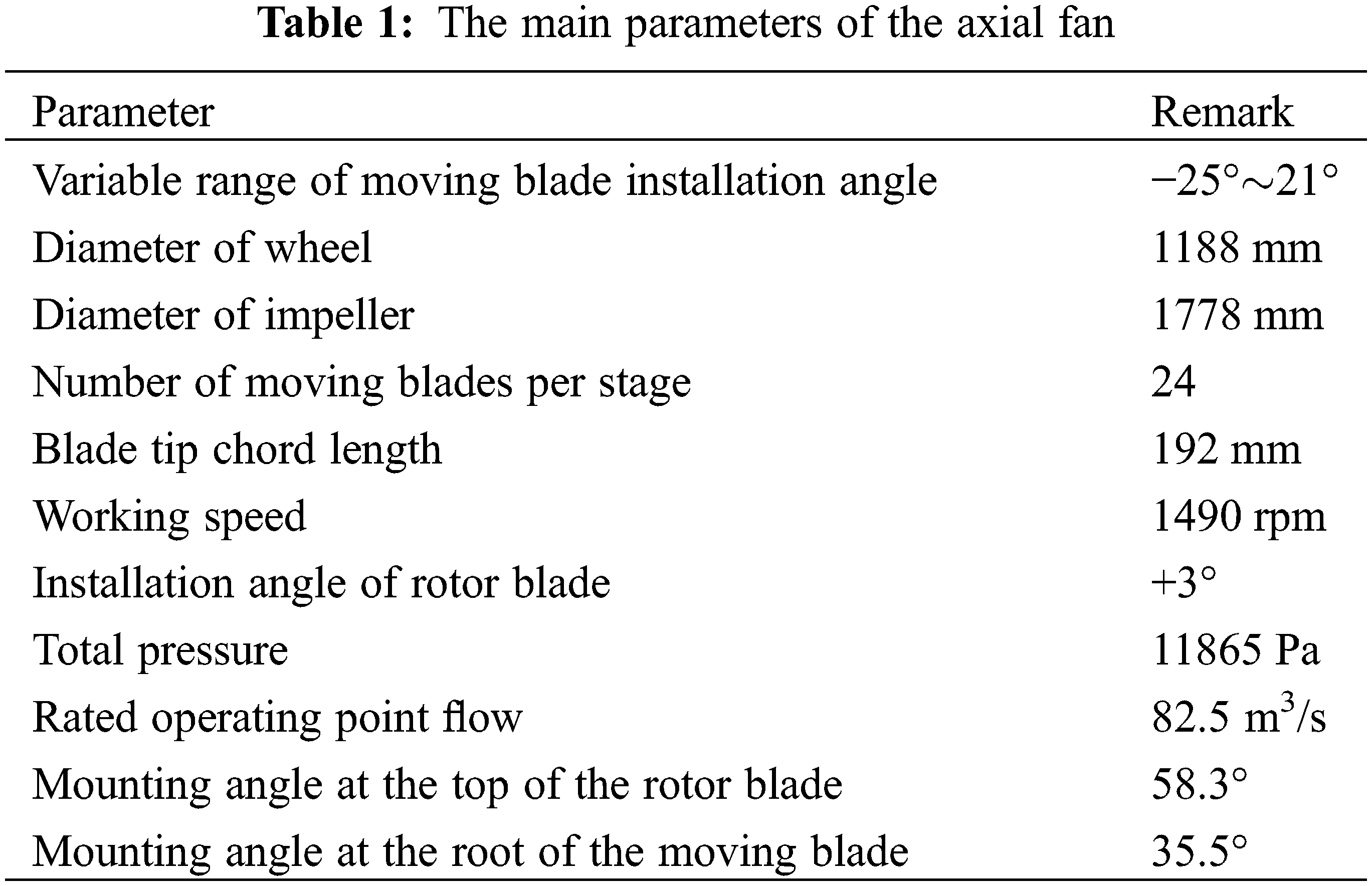
A two-stage variable-pitch axial flow primary fan is selected in this manuscript, the structure of which is shown in Fig. 1. According to the axial structure, it is mainly divided into a series of parts, such as the collector, first-stage moving blade, first-stage stationary blade, second-stage moving blade, two-stage vane, and diffuser. The main parameters of the axial fan are shown in Table 1.
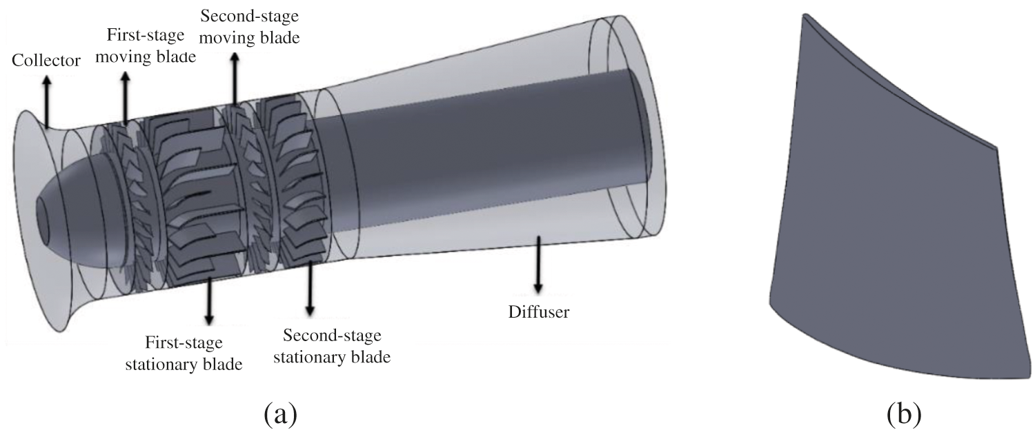
Figure 1: Two-stage variable-pitch axial flow fan diagram. (a) Fan model structure diagram (b) The first stage rotor blade structure
To explore the influence of the blade tip modification on the two-stage variable-pitch axial flow fan, four different improvement schemes are proposed. Fig. 2a shows the original tip of the first stage moving blade. In the case of a winglet at the blade top, a slot is carved into the blade top. The four different schemes are shown in Figs. 2b∼2e. Schemes 1 to 4 are all added winglets on the suction surface, and ribs at different positions are formed after different grooves on the top. The width of the winglet is twice the width of the tip, the thickness is 3 mm, the groove depth is 1.5 mm, and the rib width and groove edge distance are both 3 mm. According to the airflow direction and the number of grooves, Scheme 1 is a single counterflow rib layout groove tip based on the airflow direction and the number of grooves (the rib is 45% of the axial chord distance from the leading edge of the blade). Scheme 2 is a single forwards flow rib layout groove tip (the rib is 48% of the axial chord distance from the leading edge of the blade). A double forwards-flow rib arrangement groove tip is shown in Scheme 3 (the middle groove width is 38% of the axial chord length). Scheme 4 is a double counter-flow rib layout groove tip (the middle groove width is 38% of the axial chord distance).
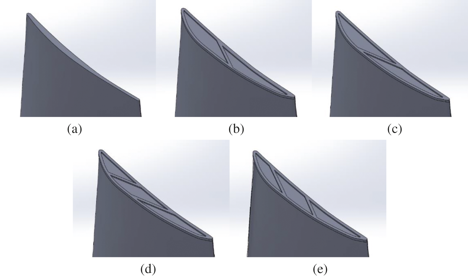
Figure 2: Different schemes of the leaf’s top structure. (a) Original (b) Scheme 1 (c) Scheme 2 (d) Scheme 3 (e) Scheme 4
2.2 Calculation Method and Boundary Conditions
The continuity equation and the three-dimensional Reynolds time-averaged N-S equation of motion are taken as the control equation. The realizable k-ε model is adopted as the turbulence model, which can effectively solve the problem of rotational motion, secondary flow and backflow [21–23]. For pressure velocity coupling, the SIMPLEC algorithm with good convergence is used. The variables and viscosity parameters in the control equation are all discretized in the second-order upwind style, and the standard wall function is adopted for the near wall. Due to the relative motion between the blade and the shell, the multireference system model is selected to simulate the steady state of the fan [24–26]. The data on the two interfaces of the upstream outlet and the downstream inlet are exchanged through an interface transfer.
The current collector is the inlet of the calculation domain, of which the velocity inlet is adopted. k and ε are determined by the empirical formulas. The diffuser is the outlet of the calculation domain, of which the free flow is selected. When the residual error of the inlet and outlet volumetric flow rate is less than 10−5, the residual error of the velocity in each direction and the parameters, such as k and ε, are less than 10−4. When the total pressure of the inlet and outlet sections does not change with time, the calculation can be considered to converge [27].
2.3 Meshing and Independent Verification
Based on the structural characteristics of the wind turbine, ICEM is used to divide the grid separately. The moving blade area and the static blade area are divided by unstructured grids, with the divided moving blade grid shown in Fig. 3. To ensure the calculation accuracy, the moving blade area has meshed, and the current collector and diffuser are structured grids.
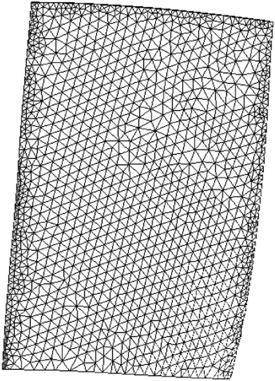
Figure 3: Moving blade grid
To verify the independence of the grids, six groups of grids are selected as follows: 5.13 million, 6.23 million, 7.18 million, 8.22 million, 9.48 million and 10.34 million. The simulation is conducted under the design flow (qv = 82.5 m3/s), the results of which are shown in Table 2. When the number of grids exceeds 8.22 million, the pressure value and efficiency value no longer change significantly. Considering the computing resources, 8.22 million grids are chosen for the simulation calculation of the entire model.
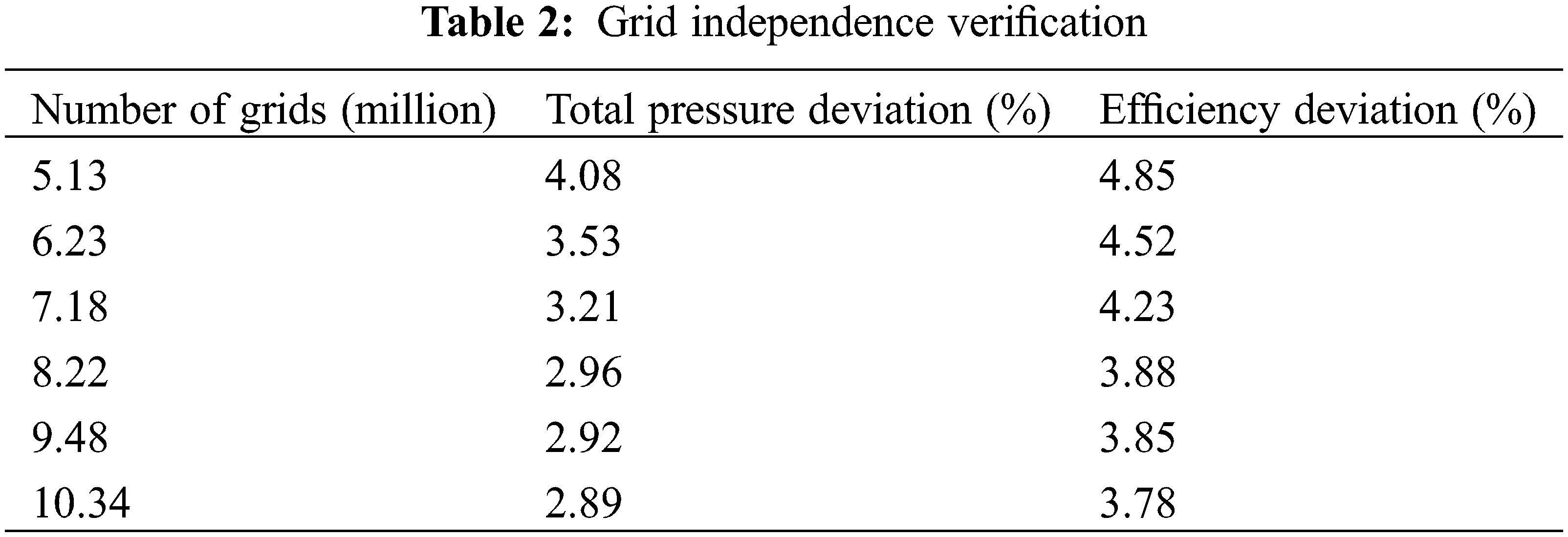
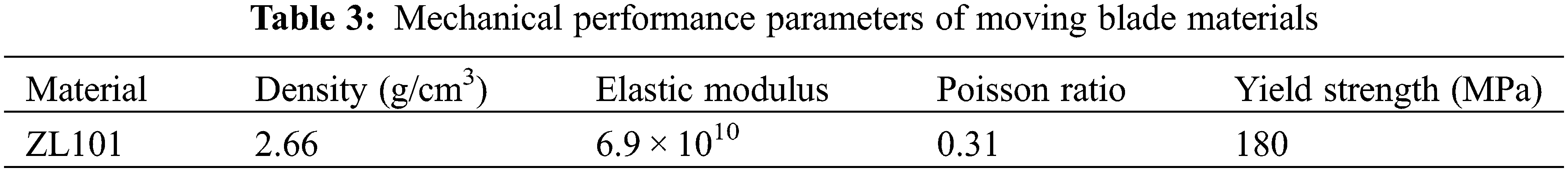
Table 3 shows the mechanical properties of fan impeller materials. The Workbench modules, Static Structural and Modal, are chosen to perform a static analysis on five different structural schemes, with 850,000 grids chosen for the numerical calculation. By default, the bottom of the moving blade is not deformed. The fixed support is used to apply a centrifugal load to the blade. Meanwhile, the blade pressure data obtained by the fluid simulation are imported, and the aerodynamic loads in various directions are simultaneously applied to the surface of the blade to perform fluid-solid coupling static force [28,29]. The specific loading process is shown in Fig. 4.
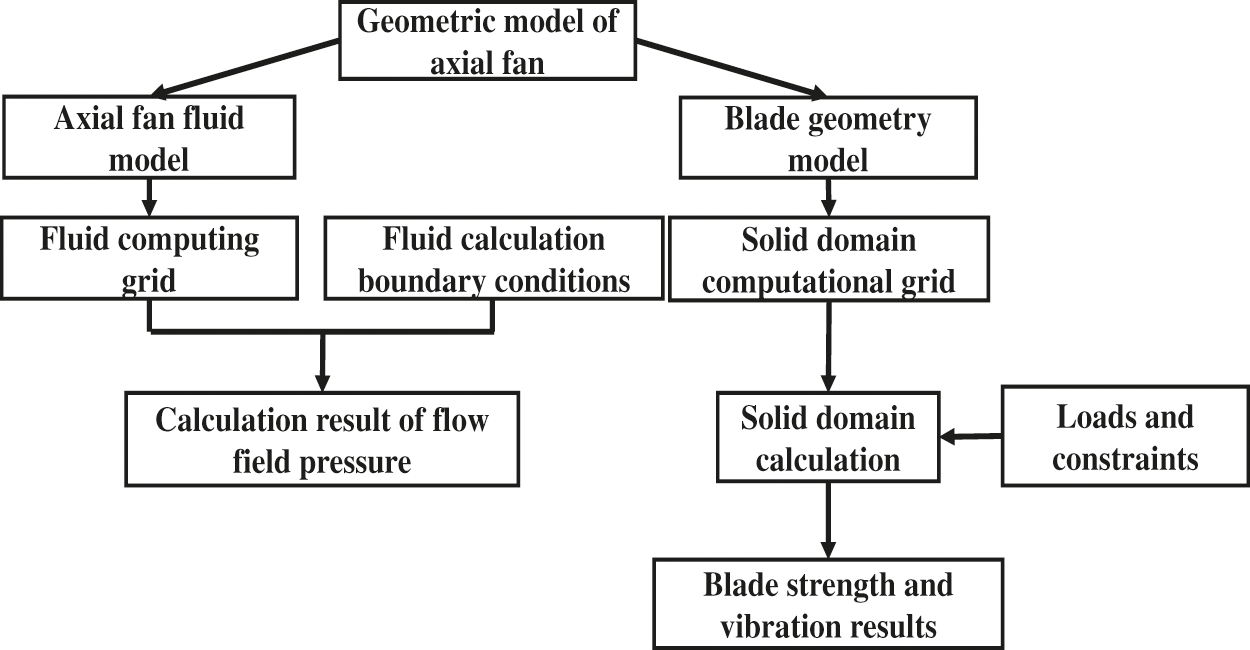
Figure 4: Fluid-solid coupling flow chart
2.5 Simulation Result Verification
The simulated value is compared to the sample value in the research flow range (80–92.5 m3/s) and the result is shown in Fig. 5. Under the full flow range, the average deviations of the full pressure and efficiency are 3.10% and 3.01%, and the deviations under the design conditions are 2.96% and 3.88%, respectively. All errors are controlled within 5%, and the results meet the accuracy requirements, which can reflect the actual operating conditions of the fan [30,31].
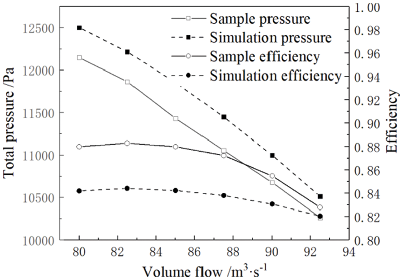
Figure 5: Comparison of simulation results and the sample values
The original blade top structure and the fan performance under different schemes are shown in Fig. 6. The research flow range, compared with the original structure, the total pressure and the efficiency under the four schemes have been improved to different degrees. Fig. 6a shows a comparison of the total pressure lift value of the four schemes in the full flow range. The increase is in the order of Scheme 4, Scheme 2, Scheme 3, and Scheme 1. Scheme 2, Scheme 3, and Scheme 4 are all on the small flow side among all the schemes. The pressure increase is more obvious, and the increased value is above 100 Pa, while the total pressure increase effect gradually weakens as the flow rate increases. The first solution has the worst effect, and the increase is relatively average under the full range of flow, approximately 90–100 Pa. The fan efficiency has improved significantly in the full flow range under the four schemes, reaching a maximum value under the design conditions (qv = 82.5 m3/s) in Fig. 6b. The improvement effect is in the order of Scheme 1, Scheme 4, Scheme 2 and Scheme 3. In addition, Scheme 1 has a slightly higher lifting capacity under low traffic than Scheme 4. As the traffic increases, the effect of upgrading is essentially the same as Scheme 4.
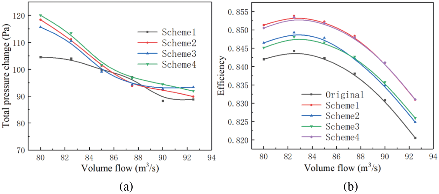
Figure 6: The effect of the blade top structure on the performance. (a) Total pressure curve (b) Efficiency curve
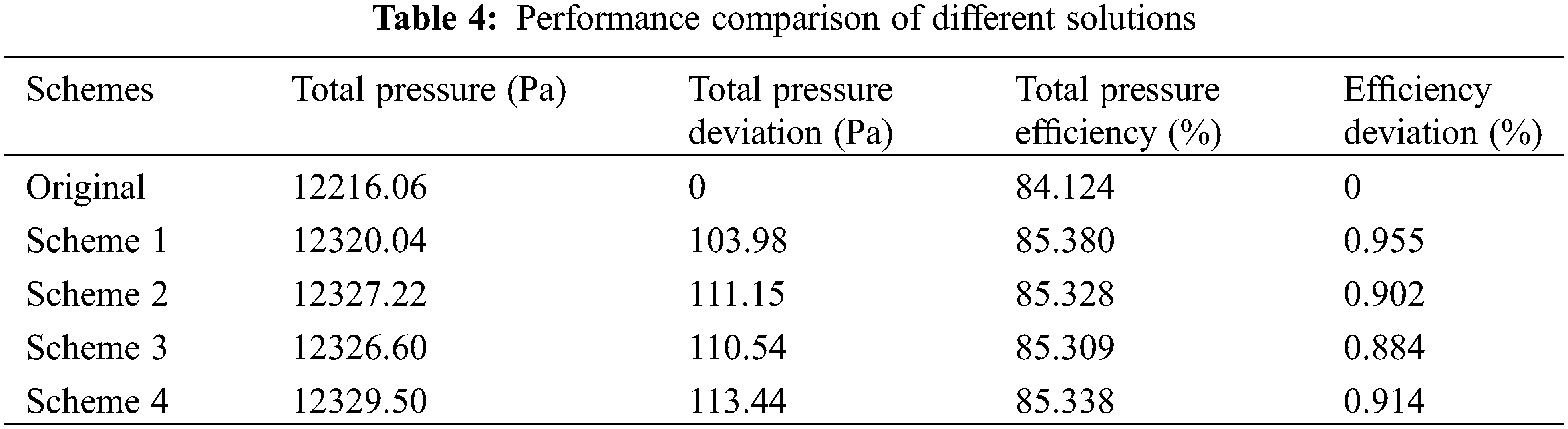
Table 4 shows the comparison of different schemes under the design flow. As shown in the table, Scheme 1 is increased to 103.98 Pa, while Scheme 2, Scheme 3, and Scheme 4 are all over 110 Pa. Scheme 4 has the most obvious improvement effect, with a value of 113.44 Pa. In terms of fan efficiency, Scheme 1 has the best improvement capability with an efficiency increase of 0.955%. The others are Scheme 4, Scheme 2, and Scheme 3, namely, 0.914%, 0.902%, and 0.884% in order, respectively. Combining Table 4 and Fig. 6, it can be seen that although Scheme 1 has the best efficiency improvement capability, it has the worst pressure improvement effect among the four schemes. Scheme 4 is only slightly worse than Scheme 1 in terms of its efficiency improvement capacity under a small flow rate, and the incensement of pressure is the best in the entire flow range. The double counter-flow ribs at the groove tip in Scheme 4 has the best performance improvement effect.
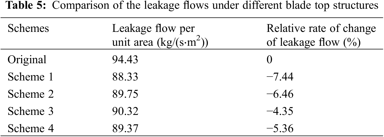
Most of the tip loss comes from the tip leakage flow, which can reflect the loss characteristics of the fan before and after tip modification. The larger the tip leakage flow is, the more prominent the leakage loss and the increase in the overall loss. Taking the large pressure difference between the suction surface and the pressure surface of the moving blade into account, the flow direction of the tip leakage flow is roughly perpendicular to the moving blade. The flow velocity in the gap is set as:
where υt is the leakage flow velocity, p1 and p2 represent the pressure surface and suction surface pressure, respectively, and ρ is the density of the medium. The relative change rate of the leakage flow rate, ψ, is obtained as:
where Qc is the leakage flow rate after the blade tip modification and Qo is the leakage flow rate under the original blade tip. As shown in Table 5, compared with the original structure, the tip leakage flow of the four schemes is reduced, to varying degrees. And this is consistent with the conclusion by Ye et al. [25]. The reductions from more to less are Scheme 1, Scheme 2, Scheme 4, and Scheme 3, reducing by 7.44%, 6.46%, 5.36%, and 4.35%, respectively.
In large rotating machinery, the blade is one of the most important components. To avoid changes in the structural strength of the blade before and after modification, which results in a large deformation, it is necessary to conduct a static analysis on the fan blade after the groove winglet is installed. After calculating the centrifugal force and aerodynamic load, the overall distribution of different schemes has changed little. The isoline of the suction surface of the first stage bucket approximates with a shape of “Λ” along with the blade height, and it is aligned from the leading edge. In the angular direction, the amount of deformation is gradually reduced. Due to the structure of the blade bottom, the thickness is larger, and the value of deformation is 0. Fig. 7a shows that the largest deformation area of the original scheme appears at the leading edge of the blade tip with a deformation value of 0.1737 mm. Considering the blade is narrow, a deformation area is appeared nearing the trailing edge in the direction of the leaf height above 60%. At the tip of the blade, the deformation changes along the chord line, and the deformation is the smallest near the trailing edge at 20%. As shown in Figs. 7b∼7e, the deformation amount under the four schemes is reduced to different degrees after installing the groove winglet, which are 0.1338, 0.1281, 0.1299, and 0.1291 mm, respectively. The largest structural deformation occurs near the leading edge and the trailing edge of the blade tip, and the transformation is mainly aimed at the tip of the blade. The width of the winglet is added, and its resistance to deformation is increased. Different from the blade top surface of the original structure, the centre of the winglet groove under the four schemes has a larger deformation. The significant deformation region of Scheme 1 and Scheme 2 is near to the middle rib in the single-rib groove, whereas the middle groove deformation area of the double-rib groove is larger and essentially occupies the entire groove in the double-rib groove.
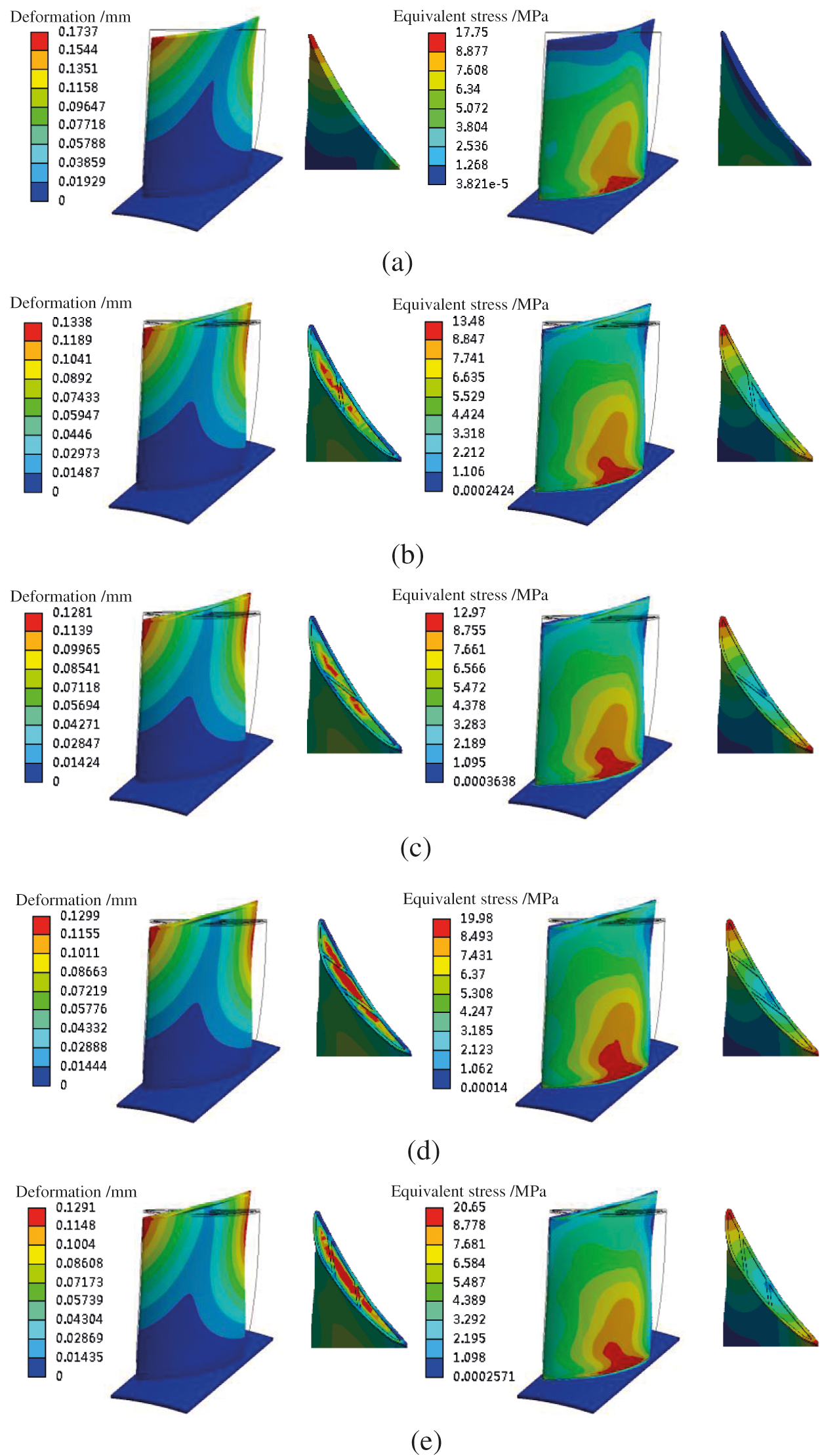
Figure 7: Deformation and stress distribution of the different structures. (a) Original (b) Scheme 1 (c) Scheme 2 (d) Scheme 3 (e) Scheme 4
In terms of equivalent stress, the use of grooved winglets has little effect on the surface stress distribution of the suction surface. The stress steadily reduces along the blade height direction in the original structure. The tip surface stress is the smallest, while the maximum stress is located at the blade root near the trailing edge and near the hub. Compared with the original structure, the maximum equivalent stress of adding a single-rib groove is reduced by a substantial amount. Scheme 1 and Scheme 2 are reduced by 24% and 27%, respectively. The equivalent stress of the double-rib groove is slightly increased, with Scheme 3 and Scheme 4 increasing by 12% and 16%, respectively. Due to the structural particularity of the winglets and grooves, the stress distribution at the tip of the blade under the four schemes is much more complicated than that of the original structure. The maximum tip stress is appeared on leading edge and trailing edge have, while the minimum stress area on the rib and end walls near the junction.
The strength check of the blades before and after the modification is mainly based on the fourth strength theory [32], where the allowable stress [σ] is defined as:
where σs is the yield limit of the material and ns is the safety factor of the material, which is generally taken as 1.5–2. In this manuscript, σs = 180 and ns = 2 when the material ZL101 is used for blades, and the allowable stress of the moving blade is 90 MPa. The maximum stress is presented in Scheme 4 among the four schemes. The peak value is only 20.65 MPa, which is far less than the allowable stress. In terms of the stiffness, the maximum deformation of the four structures is lower than that of the original structure, which meets the strength requirements and improves the overall safety margin of the blade.
At the same time, due to the changes in the force and the applied load on the surface of the fan blade before and after the blade tip modification, in order to avoid the resonance of the blade after the modification, it is necessary to perform a modal analysis on the fan blade after the groove winglet is installed. In the finite element analysis software Workbench, the static force results are applied to the wind turbine blades as prestress, and the modal analysis is performed on the blades before and after the winglet is installed. Table 6 shows the natural frequencies of the first six orders of the first-stage buckets under the original structure and the four schemes. With an increasing order, the natural frequencies of the blades are also greatly improved. After the modification, the first two orders and the fourth-order natural frequency of the four schemes have a small drop, and the third-order natural frequency is dropped by approximately 40 Hz. The difference is mainly reflected in the fifth-order natural frequency. The frequency of the two schemes under the single rib groove winglet structure increased the most, reaching 75 Hz and 78 Hz, respectively. The frequency increase of the double rib groove winglet structure scheme is also nearly 70 Hz, while the sixth-order frequency of the four schemes has risen by approximately 40 Hz.
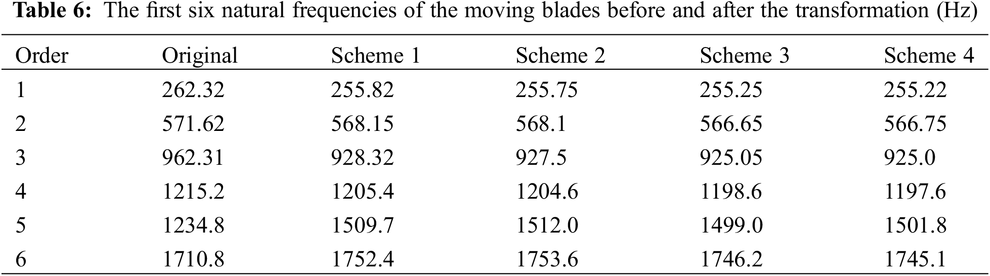
The passing frequency of the blade is defined as:
where n is the rotating speed, Z is the number of blades, k = 1 is the blade passing frequency, and k = 2, 3… is the k-th order blade passing frequency [33]. Since the revolution speed of the two-stage adjustable-blade axial fan is 1490 rpm and the number of single-stage blades is 24, the passing frequency of the blades is 596 Hz. Comparing the sixth-order natural frequencies in Table 6, all natural frequencies avoid the passing frequency. After adopting the suction surface groove winglet structure, no resonance phenomenon will occur, which leads to fatigue damage of the blade.
Four different grooves combined with a small wing tip structure were constructed in this manuscript. Within the research flow range and compared with the original structure, the total pressure and efficiency of the fan under the four schemes have been improved to different degrees. This is in line with the conclusion that the winglet tip and groove tip construction has been chosen in most recent research to improve performance. Meanwhile, few conclusions have also been obtained as follows:
1. The grooved tip is arranged with double counter-flow ribs in Scheme 4, which provides the optimum performance improvement impact. The total pressure and efficiency are increased by 113.44 Pa and 0.955%, respectively. The tip leakage flow under the four winglet solutions has different degrees than the original structure. The reductions in the schemes are as follows: Scheme 1, Scheme 2, Scheme 4 and Scheme 3, with decreases of 7.44%, 6.46%, 5.36%, and 4.35%, respectively.
2. The strength of the blades before and after the modification are checked. The blade tip stress distribution under the four schemes is more complicated than that of the original structure. Nearing the junction of the end walls, the maximum deformation of the blade is lower than that of the original structure, which meets the strength requirements and improves the overall safety margin of the blade.
3. The modal analysis of the blades before and after the winglet is added. The passing frequency of the blade is avoided by the inherent frequencies, and the resonance can not be occurred by adopting of the suction surface groove winglet structure.
Funding Statement: This research is supported by the Fundamental Research Funds for the Central Universities (No. 2021 MS121).
Conflicts of Interest: The authors declare that they have no conflicts of interest to report regarding the present study.
1. Li, H. R., Zheng, J., Dong, K. T., Li, K. L. (2020). Research on intelligent energy-saving operation of dynamically adjusted axial flow fans in all working conditions. Thermal Power Generation, 49(11), 34–39 (in Chinese). DOI 10.19666/j.rlfd.202003105. [Google Scholar] [CrossRef]
2. Zhang, Y. G. (2021). Stall analysis of two-stage adjustable blade axial flow fan in thermal power plant. Mechanical and Electrical Information, 21(5), 33–35 (in Chinese). DOI 10.19514/j.cnki.cn32-1628/tm.2021.05.015. [Google Scholar] [CrossRef]
3. Li, H. R., Zheng, J., Du, J. Z. (2021). Diagnosis and treatment of failure of sub-standard aerodynamic performance of two-stage dynamic blade adjustable axial fan. Fluid Machinery, 49(2), 66–70 (in Chinese). DOI 10.3969/j.issn.1005-0329.2021.02.010. [Google Scholar] [CrossRef]
4. Dai, J., Mou, J., Liu, T. (2020). Influence of tip clearance on unsteady flow in automobile engine pump. Fluid Dynamics & Materials Processing, 16(2), 161–179. DOI 10.32604/fdmp.2020.06613. [Google Scholar] [CrossRef]
5. Riera, W., Marty, J., Castillon, L., Deck, S. (2016). Zonal detached-eddy simulation applied to the tip-clearance flow in an axial compressor. AIAA Journal, 54(8), 2377–2391. DOI 10.2514/1.J054438. [Google Scholar] [CrossRef]
6. Wbitcomb, R. T. (1976). A Design approach and selected wind-tunnel results at high subsonic speeds for wing-tipmounted winglets. NASA Technical Reports Server. NASATN D-8260. [Google Scholar]
7. Seo, Y. C., Lee, S. W. (2013). Tip gap flow and aerodynamic loss generation in a turbine cascade equipped with suction-side winglets. Journal of Mechanical Science and Technology, 27(3), 703–712. DOI 10.1007/s12206-012-1258-x. [Google Scholar] [CrossRef]
8. Ebrahimi, A., Mardani, R. (2018). Tip-vortex noise reduction of a wind turbine using a winglet. Journal of Energy Engineering, 144(1), 04017076. DOI 10.1061/(ASCE)EY.1943-7897.0000517. [Google Scholar] [CrossRef]
9. Hui, Z., Cheng, G., Chen, G. (2021). Experimental investigation on tip-vortex flow characteristics of novel bionic multi-tip winglet configurations. Physics of Fluids, 33(1), 011902. DOI 10.1063/5.0036369. [Google Scholar] [CrossRef]
10. Saha, A. A., Acharya, S., Bunker, R., Prakash, C. (2006). Blade tip leakage flow and heat transfer with pressure-side winglet. International Journal of Rotating Machinery, 2006, 1–15. DOI 10.1155/IJRM/2006/17079. [Google Scholar] [CrossRef]
11. Zhang, C., Ji, L., Zhou, L., Zhang, Z. (2020). Effects of different blended blade tip and winglets on aerodynamic and aeroacoustic performances of diagonal fans. Aerospace Science and Technology, 106, 106200. DOI 10.1016/j.ast.2020.106200. [Google Scholar] [CrossRef]
12. Khaled, M., Ibrahim, M. M., Abdel Hamed, H. E., Abdel Gwad, A. (2019). Investigation of a small Horizontal-Axis wind turbine performance with and without winglet. Energy, 187, 1–11. DOI 10.1016/j.energy.2019.115921. [Google Scholar] [CrossRef]
13. Schabowski, Z., Hodson, H. (2013). The reduction of over tip leakage loss in unshrouded axial turbines using winglets and squealers. Journal of Turbomachinery, 136(4), 1–6. DOI 10.1115/1.4024677. [Google Scholar] [CrossRef]
14. Coull, J. D., Atkins, N. R., Hodson, H. P. (2014). Winglets for improved Aerothermal performance of high pressure turbines. Journal of Turbomachinery, 136(9), 091007. DOI 10.1115/1.4026909. [Google Scholar] [CrossRef]
15. Ameri, A. A., Steinthorsson, E., Rigby, D. L. (1998). Effect of squealer tip on rotor heat transfer and efficiency. Journal of Turbomachinery, 120(4), 753–759. DOI 10.1115/1.2841786. [Google Scholar] [CrossRef]
16. Nho, Y. C., Park, J. S., Yong, J. L., Kwak, J. S. (2012). Effects of turbine blade tip shape on total pressure loss and secondary flow of a linear turbine cascade. International Journal of Heat & Fluid Flow, 33(1), 92–100. DOI 10.1016/j.ijheatfluidflow.2011.12.002. [Google Scholar] [CrossRef]
17. Jung, Y., Choi, M., Park, J. Y., Baek, J. H. (2012). Effects of recessed blade tips on the performance and flow field in a centrifugal compressor. Proceedings of the Institution of Mechanical Engineers, Part A: Journal of Power and Energy, 227(2), 157–166. DOI 10.1177/0957650912465278. [Google Scholar] [CrossRef]
18. Li, W., Jiang, H., Zhang, Q., Lee, S. W. (2013). Squealer tip leakage flow characteristics in transonic condition. Journal of Engineering for Gas Turbines and Power, 136(4), 042601. DOI 10.1115/1.4025918. [Google Scholar] [CrossRef]
19. de Maesschalck, C., Lavagnoli, S., Paniagua, G. (2015). Blade tip carving effects on the aerothermal performance of a transonic turbine. Journal of Turbomachinery, 137(2), 1–10. DOI 10.1115/1.4028326. [Google Scholar] [CrossRef]
20. Cheon, J. H., Lee, S. W. (2015). Tip leakage aerodynamics over the cavity squealer tip equipped with full coverage winglets in a turbine cascade. International Journal of Heat and Fluid Flow, 56, 60–70. DOI 10.1016/j.ijheatfluidflow.2015.07.003. [Google Scholar] [CrossRef]
21. Song, J., Kharoua, N., Khezzar, L., Alshehhi, M. (2021). Numerical simulation of turbulent swirling pipe flow with an internal conical bluff body. Fluid Dynamics & Materials Processing, 17(2), 455–470. DOI 10.32604/fdmp.2021.014370. [Google Scholar] [CrossRef]
22. Wang, L., An, C., Wang, N., Ping, Y., Wang, K. et al. (2020). Numerical simulation of axial inflow characteristics and aerodynamic noise in a large-scale adjustable-blade fan. Fluid Dynamics & Materials Processing, 16(3), 585–600. DOI 10.32604/fdmp.2020.09611. [Google Scholar] [CrossRef]
23. Ye, X. M., Li, X. Y., Li, C. X. (2013). Numerical simulation on internal flow field of a two-stage variable vane axial flow fan. Journal of Power Engineering, 33(11), 871–877 (in Chinese). DOI 10.3969/j.issn.1674-7607.2013.11.008. [Google Scholar] [CrossRef]
24. Du, K., Li, J. (2017). Numerical study on unsteady flow and heat transfer characteristics of turbine blade groove tip. Journal of Propulsion Technology, 38(3), 551–558 (in Chinese). DOI 10.13675/j.cnki.tjjs.2017.03.010. [Google Scholar] [CrossRef]
25. Ye, X. M., Zhang, J. K., Li, C. X. (2018). Numerical investigation of blade tip shape on aerodynamic performance of a two-stage variable-pitch axial fan. Acta Aerodynamics Sinica, 36(4), 695–703 (in Chinese). DOI 10.7638/kqdlxxb-2016.0066. [Google Scholar] [CrossRef]
26. Cheng, X., Jiang, Y., Li, M., Zhang, S. (2020). Influence of the axial position of the guide vane on the fluctuations of pressure in a nuclear pump. Fluid Dynamics & Materials Processing, 16(5), 1047–1061. DOI 10.32604/fdmp.2020.010695. [Google Scholar] [CrossRef]
27. Miao, S., Zhang, H., Shi, F., Wang, X., Ma, X. (2021). Study on energy conversion characteristics in volute of pump as turbine. Fluid Dynamics & Materials Processing, 17(1), 201–214. DOI 10.32604/fdmp.2021.012950. [Google Scholar] [CrossRef]
28. Sun, C., Shang, J., Luo, Z., Li, X., Lu, Z. et al. (2020). CFD simulation and experimental study of a new elastic blade wave energy converter. Fluid Dynamics & Materials Processing, 16(6), 1147–1159. DOI 10.32604/fdmp.2020.09937. [Google Scholar] [CrossRef]
29. Kong, C., Bang, J., Sugiyama, Y. (2005). Structural investigation of composite wind turbine blade considering various load cases and fatigue life. Energy, 30(11–12), 2101–2114. DOI 10.1016/j.energy.2004.08.016. [Google Scholar] [CrossRef]
30. Ye, X. M., Li, P. M., Li, C. X. (2015). Investigation of double grooved blade tip structure on aerodynamic performance and vibration characteristic of an axial flow fan. Journal of Mechanical Engineering, 51(4), 167–174 (in Chinese). DOI 10.3901/JME.2015.04.167. [Google Scholar] [CrossRef]
31. Li, C. X., Fan, F. W., Liu, H. K., Ye, X. M. (2019). Simulation on aerodynamic performance of a variable-pitch axial flow fan with circumferentially skewed blades. Journal of Chinese Society of Power Engineering, 39(1), 41–49, 58 (in Chinese). DOI 10.3969/j.issn.1674-7607.2019.01.007. [Google Scholar] [CrossRef]
32. Qi, D. D., Long, H. Y., Li, Y. G., Dong, J. H. (2018). Fluid-structure coupling analysis of mixed flow fan based on ansys workbench. Mechanical Engineering and Automation, 47(3), 65–66+69 (in Chinese). DOI 10.3969/j.issn.1672-6413.2018.03.025. [Google Scholar]
33. Vala, J., Patel, D. K., Panchal, H. (2019). Numerical investigation of blade tip with different groove effect and its dynamic analysis of axial flow fan. International Journal of Ambient Energy, 42(15), 1785–1793. DOI 10.1080/01430750.2019.1614993. [Google Scholar] [CrossRef]
 | This work is licensed under a Creative Commons Attribution 4.0 International License, which permits unrestricted use, distribution, and reproduction in any medium, provided the original work is properly cited. |