| Fluid Dynamics & Materials Processing |
DOI: 10.32604/fdmp.2022.021541
ARTICLE
An Analytical Model for the Thermal Assessment of a Vertical Double U-Tube Ground-Coupled Heat Pump System in Steady-State Conditions
Université de Lorraine, CNRS, LEMTA, Nancy, F-54000, France
*Corresponding Author: Ali H. Tarrad. Email: ali.tarrad@univ-lorraine.fr
Received: 20 January 2022; Accepted: 21 February 2022
Abstract: An analytical model was built to predict the thermal resistance of a vertical double U-tube ground-coupled heat pump that operates under steady-state conditions. It included a geometry obstruction factor for heat transfer throughout the backfill medium due to the presence of the second loop. The verification of the model was achieved by the implementation of five different borehole configurations and a comparison with other correlations in the available literature. The model considered a U-tube spacing range between (2) and (4) times the U-tube outside diameter producing a geometry configuration factor range of (0.29–0.6). The results of the model were utilized for the assessment of the DX ground heat exchanger coupled heat pump system. For similar geometrical configurations, the borehole thermal resistance experienced a decrease as the geometry factor increased. The single U-tube borehole thermal resistance was higher than that of the double U-tube heat exchanger by (10–27)% for the examined geometry configurations. The borehole thermal resistance at tube spacing of twice the tube diameter was higher than the predicted value at the triple diameter and fell in the range of (18–34)%.
Keywords: Ground-coupled heat pumps; borehole thermal resistance; double U-tube; modeling
Nomenclature
| Parameter | Definition |
| A | Tube area, m2 |
| CF | Configuration fraction |
| COP | Coefficient of performance |
| d | Tube diameter, m |
| D | Borehole diameter, m |
| GSHE | Ground source heat exchanger |
| GSHP | Ground source heat pump |
| h | Convection heat transfer coefficient, W/m2 K |
| H | Depth |
| | Latent heat of vaporization, J/kg |
| k | Thermal conductivity, W/m.K |
| L | Length or depth, m |
| lp | Tube offset length, m |
| | Mass flow rate, kg/s |
| N | Number of loops |
| q | Heat transfer rate per unit length, W/m |
| | Heat transfer rate, W |
| R | Thermal resistance per unit length, m.K/W |
| S | Geometry shape factor, m |
| Sp | Shank spacing, m |
| t | Thickness, m |
| T | Fluid or wall temperature, K |
| ΔT | Temperature difference, K |
| WF | Wall factor defined as WF = do/t |
| Subscribes | |
| a | Tube leg (a) |
| b | Tube leg (b) |
| B | Borehole |
| cond | Condenser |
| e | Equivalent |
| f | Filling |
| fluid | Carrier heat fluid |
| g | Grout |
| gr | Ground |
| i | Inside |
| in | Inlet port |
| m | Mean |
| max | Maximum |
| mul | Multi loops |
| o | Outside |
| out | Outlet port |
| off | Offset |
| p | Pipe |
| S | Single U-tube |
| t | Total |
| Greek Letters | |
| α | Equivalency coefficient |
| β | Thermal resistance ratio factor |
| β0 | A coefficient in Eq. (4) |
| β1 | An index in Eq. (4) |
| | Borehole thermal resistance factor |
| | Tube spacing enhancement factor |
| ρ | Refrigerant density, kg/m3 |
| σ | Obstruction factor defined in Eq. (17) |
The ground is considered one of the most importantly clean, cheap, and sustainable natural energy sources on earth. Hence, it has received great attention from scientists to develop a proper technology to exploit this energy for modern life requirements. Further, the scientists kept developing optimization methodology for the thermal design and efficiency of technologies utilized in this energy field. The ground heat exchanger is inevitably important in energy transmission to or from the heat storage.
Eskilson et al. [1] modeled the performance of vertical ground heat exchangers and the interaction between boreholes in the field. They postulated that the accuracy of their model showed to be very good. Bakirci [2] conducted experimental work on the ground-source heat pump system in a cold climate region. The thermal performance results showed that the average heat-pump COP values were approximately 3.0 and 2.6 in the coldest months of a heating season. Esen et al. [3] studied experimentally and numerically the transient temperature distribution inside a borehole for a vertical U-tube heat exchanger at different depths for 150 (mm) borehole diameter. They concluded that the numerical analysis appears to be an important future tool to predict the response of GSHEs to thermal loading.
Remund [4] has shown experimentally that increasing grout thermal conductivity decreases borehole thermal resistance; it approaches the best performance at grout thermal conductivity of 1.73 (W/m.K). Liao et al. [5] presented a numerical model for the effective borehole thermal resistance of a vertical, single U-tube ground heat exchanger for a range of shank spacing. They produced a correlation that was claimed to show a better agreement with the data than available correlations. Sharqawy et al. [6] developed a 2-dimensional numerical model for the steady-state heat conduction within the borehole. They established a correlation for the prediction of the borehole thermal resistance.
Pei et al. [7] numerically simulated a GSHP with a single well, single, and double U-tube heat exchangers and the impact of these heat exchangers on the surrounding rock-soil temperature field. They concluded that the influence on the rock-soil temperature is approximately 13% higher for the double U-tube heat exchanger than that of the single U-tube one. Florides et al. [8] developed a numerical model for energy flow and temperature changes in and around a borehole. It was found that, compared to the single U-tube GSHE, the efficiencies of the double U-tube GSHEs, parallel and series configurations, are both superior. The parallel arrangement is more efficient by 26–29%, while the series configuration by 42–59%. Generally, the analytical models for GSHE implement mainly a line heat source [9,10] and cylinder heat source theory [11,12] to predict the heat transfer rate between the ground and the heat carrier fluid flowing in the GSHE.
Many correlations are available in the open literature predicting the thermal resistance of a single U-tube borehole configuration. Most of these correlations presented the U-tube in an equivalent tube configuration to evaluate the thermal resistance of the borehole. For example, the equivalent diameter of a U-tube can be shown in the form of:
where
In which the equivalent diameter corresponds to:
where n is equal to 2 for a single U-tube system and corresponds to 4 for a double U-tube ground heat exchanger. A steady-state heat transfer simulation based on the superposition technique for a cylindrical source was accomplished by Gu et al. [15]. They arrived at the following expression:
This form of equation reveals that the equivalent diameter was expressed as:
Remund [4] has formulated the borehole thermal resistance according to the U-tube leg spacing as:
where the values of the coefficient β0 and the index β1 for the average tube spacing case were 17.44 and –0.6052, respectively. The results of Eq. (4) revealed that the borehole thermal resistance approaches a peak value as the geometry ratio Sp/do equals unity. The minimum value will be experienced as the tube spacing reaches a maximum when the tubes touch the borehole surface. Sharqawy et al. [6] postulated a correlation based on a numerical model for the steady-state heat conduction within the borehole; it has the form:
Koenig [16] has analyzed the heat transfer problem in a borehole with single and multi-vertical U-tube loops. He has postulated a correlation for the borehole thermal resistance of a single U-tube heat exchanger as follows:
And another correlation for multi-vertical U-tubes in the following expression:
where RB is the borehole resistance for a single U-tube configuration described in [16].
Tarrad [17] has reported a simple correlation for predicting a borehole thermal resistance in a vertical single U-tube ground heat exchanger by expressing the equivalent diameter of Eq. (1) as:
The correlation showed an acceptable agreement with previously available ones in the open literature. Tarrad [18] presented a correlation for the borehole thermal resistance based on the equivalent tube diameter technique. He stated that the equivalent concentric tube has the expression:
The equivalency coefficient (
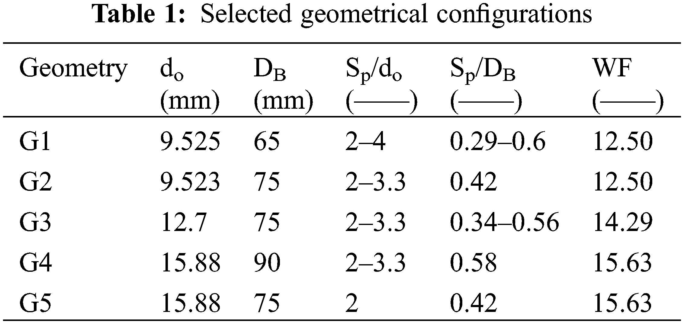
In this study, a model was built to predict the thermal resistance of the double U-tube borehole. The available double U-tube thermal resistance correlations are limited in the open literature, Shonder et al. [14] and Koenig [16]. Hence, the present model provides a new tool that implements the analytical and empirical techniques in a simple model to determine the thermal performance of the double U-tube borehole configuration. The validation of the model was based on the comparison with the available Shonder et al. [14] and Koenig [16] correlations. The tube spacing Sp was ranged between 2 and 4 times the U-tube outside diameter. This geometry parameter produces a geometry factor defined as the ratio of tube spacing to borehole diameter DB in the range of 0.29–0.6 for different configurations.
Consider a double U-tube ground heat exchanger as shown in Fig. 1 as a part of a heat pump system. The refrigerant flow in the copper U-tubes are identical, and the tubes have an equal outside diameter and shank spacing. Further, the tube layout constructs a square shape.
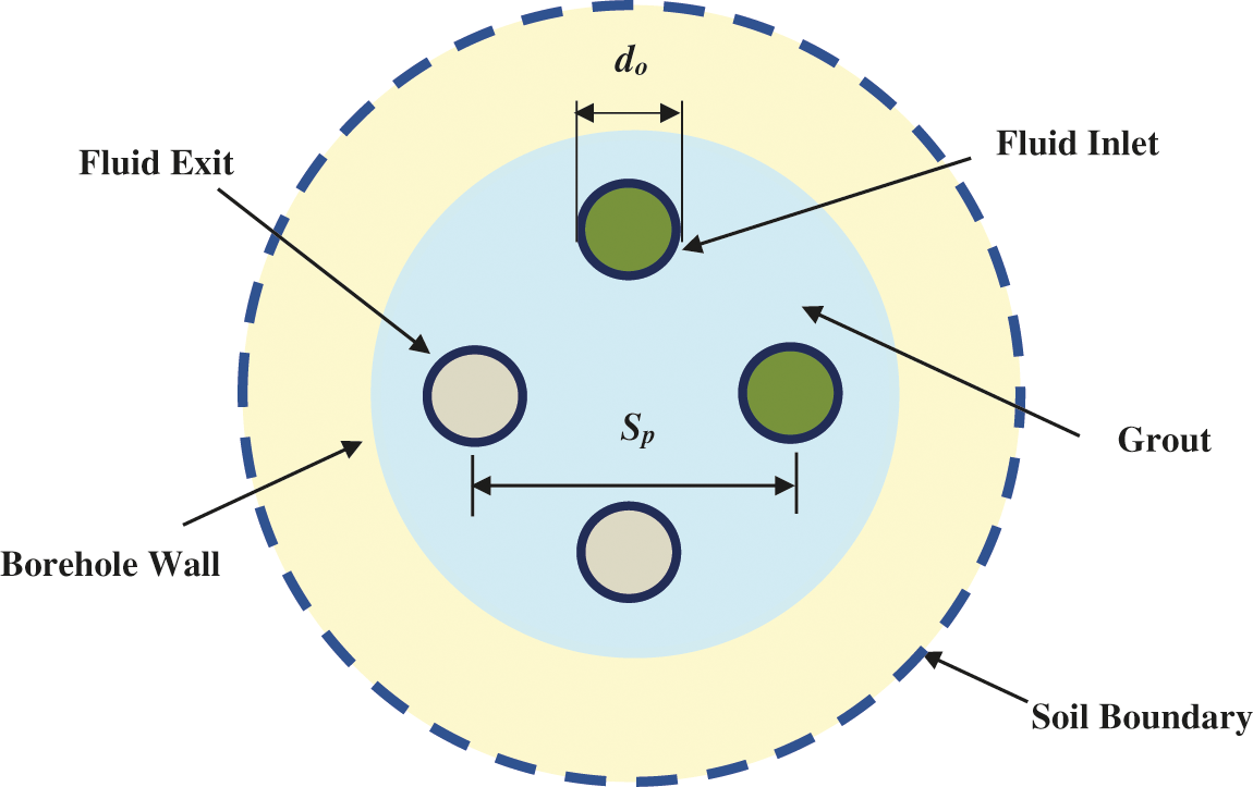
Figure 1: A vertical two U-tube ground heat exchanger
In the present work, the double U-tube ground heat exchanger is transformed into an equivalent single U-tube heat exchanger with the same geometry configuration as the original one. The U-tubes are usually symmetrically distributed and installed inside the borehole. Hence, identical physical dimensions are implemented, tube diameter, tube spacing, and length. This assumption simplifies the borehole simulation and modeling for fluid dynamics and heat transfer categories. Let us replace the downcomers with a single equivalent tube to keep the same grout volume in the borehole:
This equation yields:
This result is similar to Claesson et al. [13] and Shonder et al. [14] predictions. Similarly, the upward flow legs may also be presented by Eq. (10). This procedure reduces the original double U-tube to an equivalent single U-tube with a fixed backfill material volume in the borehole. This technique is essential for transient heat transfer modeling of the borehole.
2.2 Equivalent Tube Eccentricity
The hypothetical equivalent tube is chosen to be positioned eccentrically in the borehole. The position along the horizontal axis is selected to maintain a fixed distance between the tube legs of the equivalent U-tube as that of the original U-tube configuration. It is deduced from:
Using Eqs. (10) and (11) gives the eccentricity of the equivalent tube as:
Simplifying and arranging this expression yields:
Therefore, the double U-tube is transformed to an equivalent single U-tube, as shown in Fig. 2, in which a dotted line presents the far distance undisturbed soil.
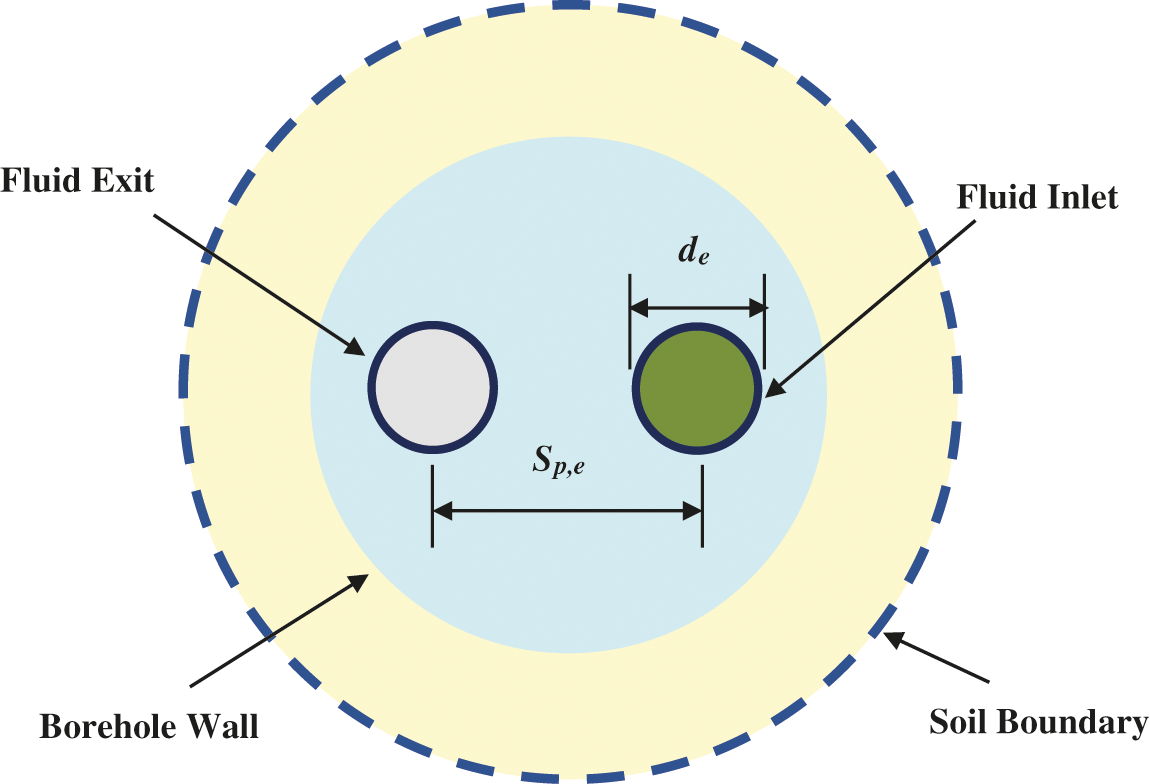
Figure 2: Equivalent system for a double U-tube ground heat exchanger
The shape factor of the equivalent tube is obtained from the relation presented in Holman [25] for an eccentric tube. For its derivation, two-dimensional heat conduction was presumed between the boundaries that are maintained at uniform temperatures as:
The thermal resistance of the eccentric tube is calculated from:
Tarrad [19] developed a model to predict the thermal resistance of a single U-tube loop in a borehole. Fig. 3 illustrates the thermal resistance circuit.
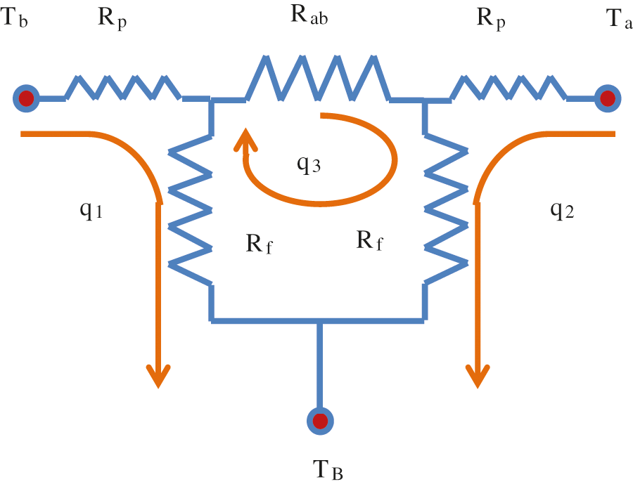
Figure 3: The thermal circuit presentation for a single U-tube heat exchanger [19]
Applying the outcomes of the Tarrad [19] model of a single U-tube heat exchanger to the equivalent U-tube borehole configuration shown in Fig. 2 yields:
The obstruction factor was obtained for the equivalent single loop as:
The obstruction factor value lies in (
For the case of copper tubes implemented in the DX ground heat exchangers, the pipe thermal resistance corresponds to a small value. Hence, its contribution to the borehole resistance is negligible. In a DX U-tube ground source coupled heat pump system, the heat exchanger plays the role of evaporator or condenser, which experiences a phase change process with negligible thermal resistance. Such phenomena always occur at isothermal conditions for pure fluids, azeotrope blends, and non azeotropic mixtures with negligible temperature glide such as R-410A. Hence, the mean temperature of the fluids inside tubes corresponds to the evaporation or condensation temperature of the refrigerant. For such conditions, Eq. (15) is still valid for predicting borehole thermal resistance of the double U-tube ground heat exchanger. Under normal operating conditions, when the process of condensation or evaporation takes place at a constant temperature, the thermal short-circuiting between the downward and upward tubes is zero. The latter condition could also be assumed for the case of the indirect heat exchanger with acceptable approximation due to the slight fluid temperature difference between both U-tube legs.
The limitation of the U-tubes outer circle diameter for practical applications of the ground heat exchanger is controlled by the relation expressed by Koenig [16]:
Rearranging this relation in terms of the tube spacing Sp gives:
This expression shows that the maximum practical tube spacing inside the borehole is controlled by:
Eq. (21) provides a practical tool for locating the U-tube inside the borehole and avoiding the critical case where the tube legs are close to the borehole boundary. However, fabricating the U-tube with a considerable value of Sp leads to close tube legs to the borehole boundary. As a result, the heat transfer process can be enhanced dramatically but deteriorate the borehole’s mechanical structure, leading to a failure for the ground heat exchanger.
Due to the lack of available experimental data for a double U-tube borehole configuration, it was decided to verify the present model by comparing it with previously published correlations in the open literature, namely Shonder et al. [14] and Koenig [16]. The proposed model was examined with several heat exchanger configurations of various tube diameters do, borehole sizes DB, and center to center tube spacings Sp. The thermal mechanism in a ground condenser of a non-azeotropic refrigerant was utilized to predict the borehole thermal resistance and compared with other investigators under similar operating conditions. The effect of the backfill material on the thermal performance of examined heat exchanger was represented by the practical range of thermal conductivity of the grout. The following describes in detail the examined double U-tube heat exchanger geometry:
1—A copper U-tube and borehole geometry dimensions are shown in Table 1. The selected physical dimensions of the borehole configurations cover practical industrial applications for copper tubing in the ground heat exchangers. It possesses a high thermal conductivity of about 400 (W/m.K) with negligible thermal resistance.
Although the U-tube has been selected to possess equal tube sizes for the downward and upward comers, it is possible to fabricate the ground condenser or evaporator with different tube sizes on both sides. For example, it is practical to select the downcomer in condensers, which passes the vapor with a bigger size than that of the liquid phase upward comer, Maritime Geothermal, Ltd. (Canada) [26].
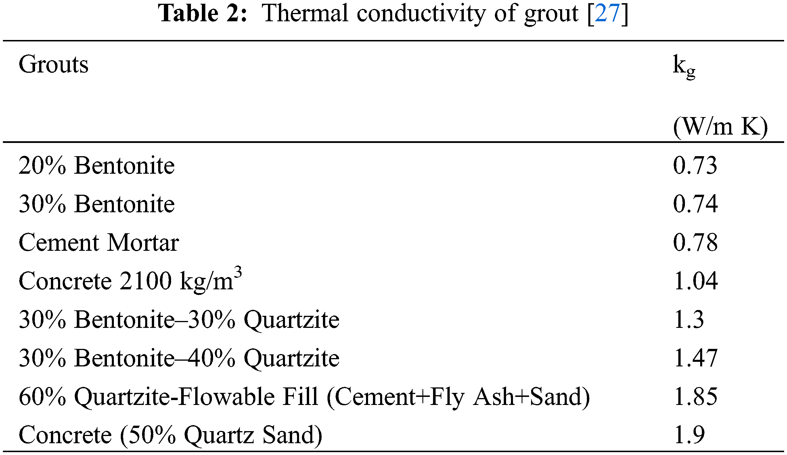
2—The grout material should possess reasonable thermal, physical, and mechanical properties to facilitate the heat exchange between the working fluid and the surrounding soil. Table 2 depicts the grout thermal conductivity of some selected grouting materials used in industrial applications in the range of 0.73–1.9 (W/m.K) [27].
3—R-410A is circulated through the examined ground single and double U-tube DX heat exchangers. Huang et al. [28] have reported data for condensation of R-410A/oil mixture at mass flux density ranging between 200 and 600 (kg/m2 s) and heat flux in the range of 4–19 (kW/m2). For condensation at (40)°C, the heat transfer coefficient of pure R-410A was within 2.4–4.6 (kW/m2°C) for the test range of vapor quality 0.2–0.9 and a tube diameter of 5 (mm). Kim et al. [29] reported their experimental data for condensation heat transfer coefficient in 9.52 (mm) outside diameter. The R-410A condensation heat transfer coefficient was ranged between 2 to 3 (kW/m2°C) depending on vapor quality at a heat flux of 11 (kW/m2), condensation temperature of 45°C, mass flux velocity of 273–287 (kg/m2 s), and vapor quality of 0.1–0.9. Therefore, a typical condensation heat transfer coefficient of 3000 (W/m2 K) was selected to verify the models [28, 29].
3.1 Double Loops Thermal Resistance
The variation of the borehole thermal resistance with the geometry factor Sp/DB and grout thermal conductivity for two configurations is illustrated in Fig. 4.
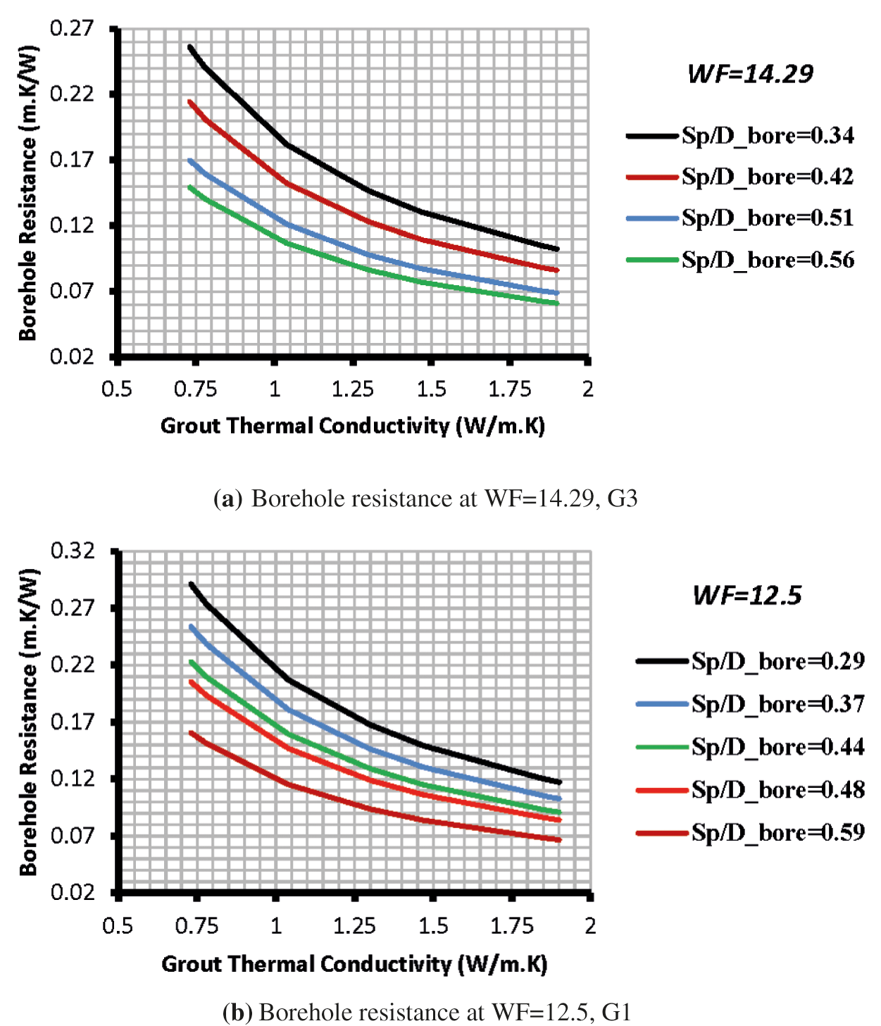
Figure 4: Comparison of borehole thermal resistance for double U-tube loops at different geometry factors
The borehole thermal resistance decreased as the geometry factor increased and vice versa. This is because increasing the geometry factor Sp/DB results in increasing spacing of the U-tube legs, which reveals a lower thermal resistance, as was proved by Remund [4], Gu et al. [15], Tarrad [19], and Sagia et al. [30]. Further, as the ratio increases, the two legs will be situated closer to the borehole wall, minimizing the grout resistance. Similarly, the borehole’s thermal resistance is also shown a declination as the grout thermal conductivity rises and approaches a minimum for the higher tested thermal conductivity due to reducing the temperature gradient through the grout layer.
3.2 Double/Single Loops Comparison
Fig. 5 illustrates a comparison of borehole thermal resistance between single and double U-tube heat exchangers for G3 and G1 configurations at WF of 14.29 and 12.5, respectively. Both tube configurations showed a decrease in the thermal resistance with geometry ratio increase. This is due to moving the tube legs closer to the borehole wall and reducing the grout layer covering the tubes for the single and double U-tube heat exchangers. The results showed that the double U-tube’s predicted values of borehole thermal resistance are less than that of the single one. The influence of the U-tube spacing is represented by:
where the subscriptions 2 & 3 refer to 2 do and 3 do tube spacing, respectively. The lower tube spacing 2 do exhibited a higher thermal resistance than that of 3 do in the range of 22–24 % for the single U-tube; it fell in the range of 32–34% for the double U-tube case (Fig. 5a). The corresponding values of
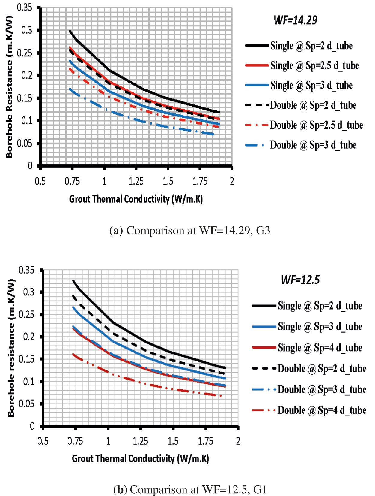
Figure 5: Comparison of the borehole thermal resistance between the single and double U-tube heat exchangers
The performance comparison of single to that of the double U-tube was based on the borehole thermal resistance measure as follows:
The enhancement of the heat transfer rate for the double U-tube depends on the tube spacing criterion. Increasing the U-tube legs improves the heat transfer rate and minimizes the borehole thermal resistance. In the small tube size of 9.53 mm, G1 configuration, the reduction percentage of the thermal resistance of the double U-tube was lower than that of the (12.7) mm tube size, G3. The values of
The enhancement of the heat transfer area inside a borehole can improve the heat transfer performance, improving the thermal efficiency of the GSHP system. Such an increase could be achieved throughout the implementation of more than one U-tube inside the borehole, larger tube diameter, and or increase the thermal conductivity of the backfill. This was also confirmed by the experimental work conducted by Jalaluddin et al. [31], who found that the heat transfer capacity of a single-U-heat exchanger is smaller than that of a double-U-heat exchanger due to its reduced heat transfer area.
The results of the borehole thermal resistance of the single and double U-tube configuration showed a vital role for tube spacing Sp. For example, the results of the single U-tube overlapped with the double U-tube configuration for both G1 and G3 at the examined geometry and grout thermal conductivity ranges. The results for the G1 configuration showed that the borehole thermal resistance of the single U-tube at Sp of 4 do was similar to those of the double U-tube ones at Sp of 3 do. They fell in the range of 0.09 (m.K/W) and 0.22 (m.K/W) predicted at grout thermal conductivity of 1.9 and 0.73 (W/m K), respectively. Similar behavior was also revealed for G3; the respective values of borehole thermal resistance of the single U-tube at Sp = 2.5 do coincided with those of the double U-tube configuration at Sp= 2 do. They fell in the range of 0.1 (m.K/W) and 0.25 (m.K/W) as predicted at grout thermal conductivity of 1.9 and 0.73 (W/m K), respectively.
3.2.2 Borehole and U-Tube Sizes
The results showed that increasing the borehole diameter for the same U-tube configuration, diameter, and spacing, caused an increase in the borehole thermal resistance (Fig. 6). This behavior is because increasing the borehole diameter will increase the grout layer around the tubes and, hence, thermal resistance.
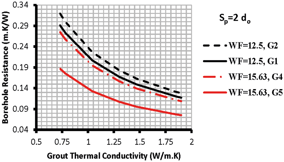
Figure 6: Effect of borehole size on the RB
Fig. 7 reveals that increasing the U-tube diameter reduces thermal resistance and vice versa. Hence, the geometry assigned as G5 produced the lower resistance, and G2 possessed the higher corresponding value.
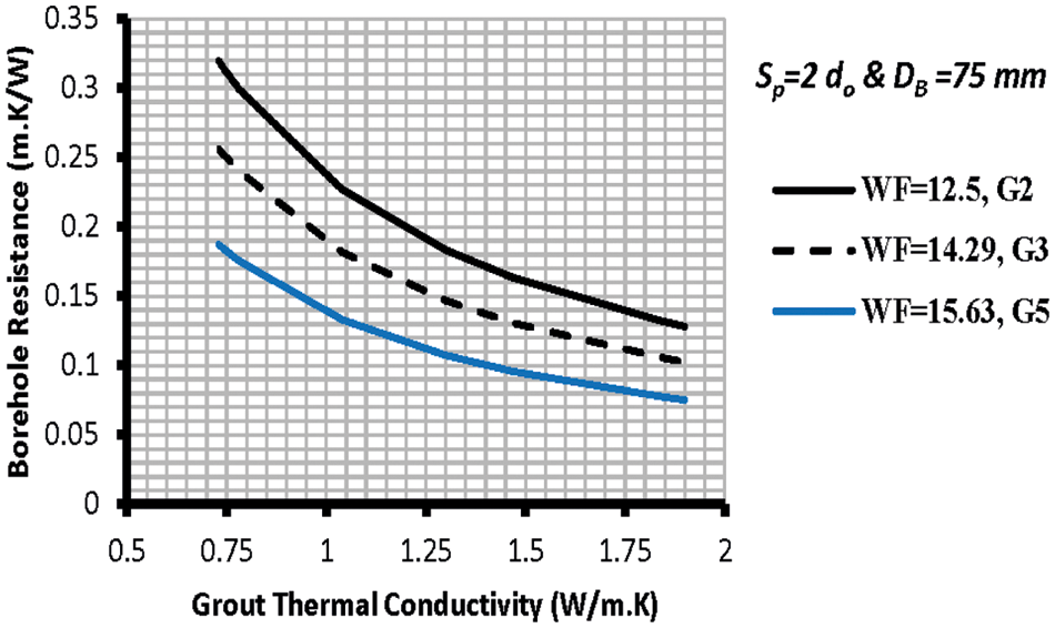
Figure 7: RB at fixed DB for the double U-tube
Two of the available correlations for the borehole thermal resistance predictions are used to verify the outcome of the present work. Fig. 8 compares the borehole thermal resistance with Koenig [16] and Shonder et al. [14] correlations for the G3 and G1 U-tube configurations.
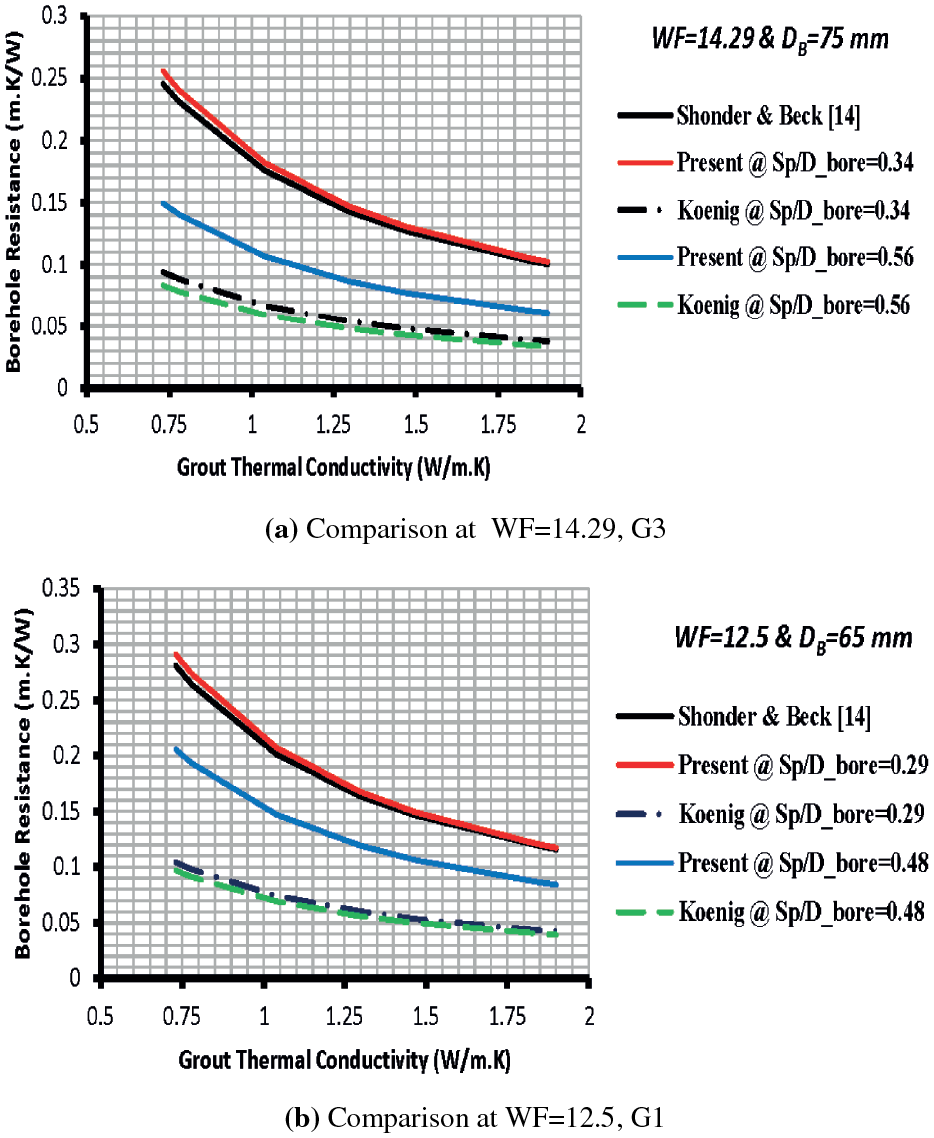
Figure 8: Comparison of the predicted borehole thermal resistance of double U-tube configurations with other investigators
Shonder et al. [14] correlation didn’t interact with the U-tube spacing for geometry configurations G1 and G3. Koenig’s [16] analytical model showed a slight response to the tube spacing for both of the considered arrangements (Fig. 8). Both examined correlations showed the same data trend as those of the present work for all configurations regardless of the tube spacing. The present model exhibited the exact numerical values of the borehole thermal resistance as those of Shonder et al. [14] ones for both geometries G1 and G3 at 0.29 and 0.34 geometry factors, respectively. The predicted borehole thermal resistance for G1 by Koenig [16] at Sp/DB of 0.29 was lower than those of the present work and Shonder et al. [14] estimations by 64%. It was lower than that predicted by the current work at Sp/DB of 0.48 by 54% for G1 configuration. Koenig [16] revealed lower thermal resistance than the present work and Shonder et al. [14] correlations by 63–67% at Sp/DB of 0.34 for G3 configuration. It was lower than that predicted by the present work at Sp/DB of 0.56 by 45%.
The above discrepancies in the estimation of the borehole thermal resistance will be reflected in the total required length of the U-tube heat exchanger and borehole depth. Therefore, the borehole thermal resistance is the critical factor in the ground heat exchanger design thermally and economically. Further, the soil thermal resistance has been proven to be a time-dependent criterion; however, it approaches a steady-state condition after one year of continuous operation [32]. Therefore, the total thermal resistance of a ground heat exchanger is often considered a constant numerical value for thermal design of their sizes.
Furthermore, the depth of the borehole also depends on the available temperature difference between the carrier heat transfer fluid and the far distance undisturbed soil temperature, and the latter varies according to the geography and climate changes. Therefore, this temperature difference represents the potential driving force for heat delivery in the borehole/soil structures. Consequently, the borehole depth is estimated from the following expressions for given operating conditions:
The fluid temperature Tfluid,m corresponds to the carrier heat fluid’s saturation temperature Tfluid, sat at the operating pressure for evaporators and condensers. For other cases where there is a temperature difference between the entering and leaving ports of the carrier heat fluid, it is feasible to use the mean temperature from:
Hence, it is essential to predict an accurate value of the borehole thermal performance to avoid overestimating the ground heat exchanger size and its cost. As a result, it is expected that the Koenig [16] model predicts the shortest U-tube length among the examined models. On the other hand, the Shonder et al. [14] correlation exhibited the most significant heat exchanger length, and implicitly the cost for the examined operating conditions.
An analytical model was derived and possessed the obstruction factor for heat transfer in the borehole due to the presence of the second tube leg in the flow direction. The consistency of the borehole thermal resistance interaction with different geometry factors Sp/DB was revealed when compared with previously published work in the open literature. The borehole thermal resistance of the single U-tube was higher than that of the double U-tube by 10–27%, depending on the geometry configuration. The borehole thermal resistance experienced a reduction as the U-tube legs got closer to the borehole wall for both single and double U-tube heat exchangers. The borehole thermal resistance at tube spacing of twice the tube diameter was higher than that at the triple diameter and fell in the range of 18–34%. Increasing the geometry factor Sp/DB or geometry ratio Sp/do reduces the borehole thermal resistance and hence increases the heat transfer rate. Similar borehole geometry configurations produced lower thermal resistance for a bigger U-tube size than a smaller one. The present and Koenig [16] models showed an agreement in the general trend of the borehole thermal resistance with the ground heat exchanger configuration. The borehole thermal resistance showed independence on the grout thermal conductivity, an essential factor in assessing the GSHE design.
The model may be expanded to utilize different tube sizes for the vapor and liquid phase sides in DX condensers and evaporators. Furthermore, examining the present model for the borehole thermal resistance with a carrier heat fluid without changing phases like water and brines. Finally, the model can be integrated for the borehole’s transient heat transfer mechanism modeling.
Acknowledgement: The author expresses his sincere thanks to the (PAUSE) Program Administration of Collège de France and the University of Lorraine for their valuable support in completing this work.
Funding Statement: The author received no specific funding for this study.
Conflicts of Interest: The author declares that he has no conflicts of interest to report regarding the present study.
1. Eskilson, P., Claesson, J. (1988). Simulation model for thermally interacting heat extraction boreholes. Numerical Heat Transfer, 13(2), 149–165. [Google Scholar]
2. Bakirci, K. (2010). Evaluation of the performance of a ground-source heat-pump system with series GHE (ground heat exchanger) in the cold climate region. Energy, 35(7), 3088e96–3096. DOI 10.1016/j.energy.2010.03.054. [Google Scholar] [CrossRef]
3. Esen, H., Inalli, M., Esen, Y. (2009). Temperature distributions in boreholes of a vertical ground-coupled heat pump system. Renewable Energy, 34(12), 2672–2679. DOI 10.1016/j.renene.2009.04.032. [Google Scholar] [CrossRef]
4. Remund, C. P. (1999). Borehole thermal resistance: Laboratory and field studies. ASHRAE Transactionss, 105, 439–445. [Google Scholar]
5. Liao, Q., Zhou, C., Cui, W., Jen, T. C. (2012). Effective borehole thermal resistance of a single U-tube ground heat exchanger. Numerical Heat Transfer, Part A: Applications, 62(3), 197–210. DOI 10.1080/10407782.2012.691061. [Google Scholar] [CrossRef]
6. Sharqawy, M. H., Mokheimer, E. M., Badr, H. M. (2009). Effective pipe-to-borehole thermal resistance for vertical ground heat exchangers. Geothermics, 38(2), 271–277. DOI 10.1016/j.geothermics.2009.02.001. [Google Scholar] [CrossRef]
7. Pei, G., Zhang, L. (2016). Heat transfer analysis of underground U‐type heat exchanger of ground source heat pump system. SpringerPlus, 5(1), 1863. DOI 10.1186/s40064-016-3548-8. [Google Scholar] [CrossRef]
8. Florides, G. A., Christodoulides, P., Pouloupatis, P. (2013). Single and double U-tube ground heat exchangers in multiple-layer substrates. Applied Energy, 102(2), 364–373. DOI 10.1016/j.apenergy.2012.07.035. [Google Scholar] [CrossRef]
9. Muttil, N., Chau, K. W. (2006). Neural network and genetic programming for modeling coastal algal blooms. International Journal of Environment and Pollution, 28(3/4), 223–238. DOI 10.1504/IJEP.2006.011208. [Google Scholar] [CrossRef]
10. Ingersoll, L. R., Zobel, O. J., Ingersoll, A. C. (1948). Heat conduction with engineering and geological application. New York, McGraw Hill. [Google Scholar]
11. Carslaw, H. S., Jaeger, J. C. (1959). Conduction of heat in solids. 2nd edition. London: Oxford University Press. [Google Scholar]
12. Ingersoll, L. R., Zobel, O. J., Ingersoll, A. C. (1954). Heat conduction with engineering, geological and other applications. revised edition, WI 53706 USA. Madison, University of Wisconsin Press. [Google Scholar]
13. Claesson, J., Dunand, A. (1983). Heat extraction from the ground by horizontal pipes-A mathematical analysis. Stockholm: Document D1, Swedish Council for Building Research [Google Scholar]
14. Shonder, J. A., Beck, J. V. (1999). Determining effective soil formation thermal properties from field data using a parameter estimation technique. ASHRAE Transactions, 105, 458–466. [Google Scholar]
15. Gu, Y., O.’Neal, D. L. (1998). Development of an equivalent diameter expression for vertical U-tubes used in ground-coupled heat pumps. ASHRAE Transaction, 104(2), 347–355. [Google Scholar]
16. Koenig, A. A. (2015). Thermal resistance of borehole heat exchangers composed of multiple loops and custom shapes. Geothermal Energy, 3(10), 1–14. DOI 10.1186/s40517-015-0029-1. [Google Scholar] [CrossRef]
17. Tarrad, A. H. (2019). A borehole thermal resistance correlation for a single vertical DX U-tube in geothermal energy application. American Journal of Environmental Science and Engineering, 3(4), 75–83. DOI 10.11648/j.ajese.20190304.12. [Google Scholar] [CrossRef]
18. Tarrad, A. H. (2020). A perspective model for borehole thermal resistance prediction of a vertical U-tube in geothermal heat source. Athens Journal of Technology and Engineering, 7(2), 73–92. DOI 10.30958/ajte.7-2-1. [Google Scholar] [CrossRef]
19. Tarrad, A. H. (2020). Development of analytical model for a vertical DX single U-tube ground-coupled heat pump system. Global Journal of Researches in Engineering, J: General Engineering, 20(3), 1–14. [Google Scholar]
20. Tang, F. J. (2020). Numerical investigation on the ground heat exchanger installed in shallow depth soils (Ph.D. Thesis). Electric Power. Université de Strasbourg, France. [Google Scholar]
21. Tarrad, A. H. (2020). A 3-dimensional borehole numerical modeling for single and double U-tube ground-coupled heat pump. COMSOL 2020 Conference, Grenoble, France. [Google Scholar]
22. Tarrad, A. H. (2021). A 3-dimensional numerical thermal analysis for a vertical double U-tube ground coupled heat pump. International Journal of Chemical Engineering and Applications, 12(2), 12–16. DOI 10.18178/ijcea.2021.12.2.789. [Google Scholar] [CrossRef]
23. Tarrad, A. H. (2021). A 3-dimensional numerical thermal analysis for the configuration effect of a single and double U-tube on the borehole performance. Proceedings of the ASME, 2021 15th International Conference on Energy Sustainability,Paper No: ES2021-60659. USA, DOI10.1115/ES2021-60659 [Google Scholar] [CrossRef]
24. Tarrad, A. H. (2021). A numerical analysis for the effect of the borehole characteristics and carrier fluid flow on the thermal performance of ground heat exchangers. International Journal of Mechanical and Production Engineering, 9(9), 19–25. [Google Scholar]
25. Holman, J. P. (2010). Heat Transfer, 10th edition, pp. 83–86. New York, McGraw-Hill. [Google Scholar]
26. Maritime Geothermal, Ltd. (2022). Installation Manual,Direct Expansion Energy Module Heat Pumps, NORDIC® models EM (DX) 45-55-65. https://www.manualslib.com/manual/1299201/Maritime-Geothermal-Nordic.html.Retrieved in 17/1/2022. [Google Scholar]
27. Gaia Geothermal (2009). Ground Loop Design Software. GLD. [Google Scholar]
28. Huang, X., Ding, G., Hu, H., Zhu, Y., Gao, Y. et al. (2010). Condensation heat transfer characteristics of R410a-oil mixture in 5 mm and 4 mm outside diameter horizontal microfin tubes. Experimental Thermal and Fluid Science, 34(7), 845–856. [Google Scholar]
29. Kim, M., Shin, J. (2005). Condensation heat transfer of R-22 and R410a in horizontal smooth and micorofin tubes. International Journal of Refrigeration, 28(6), 949–957. DOI 10.1016/j.ijrefrig.2005.01.017. [Google Scholar] [CrossRef]
30. Sagia, Z., Stegou, A., Rakopoulos, C. (2012). Borehole resistance and heat conduction around vertical ground heat exchangers. Open Chemical Engineering Journal, 6(1), 32–40. DOI 10.2174/1874123101206010032. [Google Scholar] [CrossRef]
31. Jalaluddin, A., Miyara, K., Tsubaki, S., Inoue, K., Yoshida, K. (2011). Experimental study of several types of ground heat exchanger using a steel pile foundation. Renewable Energy, 36(2), 764–771. DOI 10.1016/j.renene.2010.08.011. [Google Scholar] [CrossRef]
32. Garbai, L., Méhes, S. (2008). Heat capacity of vertical ground heat exchangers with single U-tube installation in the function of time. WSEAS Transactions on Heat and Mass Transfer, 3(3), 177–186. [Google Scholar]
 | This work is licensed under a Creative Commons Attribution 4.0 International License, which permits unrestricted use, distribution, and reproduction in any medium, provided the original work is properly cited. |