| Fluid Dynamics & Materials Processing |
DOI: 10.32604/fdmp.2022.019617
ARTICLE
LES Analysis of the Unsteady Flow Characteristics of a Centrifugal Pump Impeller
1School of Metrology and Measurement Engineering, China Jiliang University, Hangzhou, China
2Leo Group Pump Co., Ltd., Taizhou, China
3Zhijiang College, Zhejiang University of Technology, Hangzhou, China
*Corresponding Author: Denghao Wu. Email: wdh@cjlu.edu.cn
Received: 02 October 2021; Accepted: 21 February 2022
Abstract: Stall phenomena increase the complexity of the internal flow in centrifugal pump impellers. In order to tackle this problem, in the present work, a large eddy simulation (LES) approach is applied to determine the characteristics of these unstable flows. Moreover, a vorticity identification method is used to characterize quantitatively the vortex position inside the impeller and its influencing area. By comparing the outcomes of the numerical simulations and experimental results provided by a Particle Image Velocimetry (PIV) technique, it is shown that an apparent “alternating stall” phenomenon exists inside the impeller when relatively small flow rate conditions are considered. The stall is generated near the suction side of the blade inlet, grows towards the high-pressure side of the blade in the circumferential direction, and gradually attenuates. As the flow rate decreases, the number of stalls remains unchanged, while the related influencing area and strength gradually increase and the circumferential velocity increases.
Keywords: Centrifugal pump impeller; large eddy simulation; unsteady flow; stalls; vorticity
When a centrifugal pump works under stall conditions, the flow structures in a centrifugal pump impeller are highly complex, inducing unstable flow characteristics and producing severe pressure fluctuations inside the pump. However, the pump’s flow instability mechanism and its influence on its characteristics still require further study.
Advanced internal flow measurements and numerical calculations have been carried out to investigate the evolution of flow states in centrifugal pumps and understand this remarkable flow phenomenon. Sinha et al. [1] used PIV to visualize quantitatively the turbulent velocity field and the vortex field in a centrifugal pump with radial guide vanes, finding that the wake structure had occupied the entire flow passages of a pump. The guide vane’s boundary layer and turbulence structure were strongly affected by the flow from the impeller. Afterward, the researchers applied these measurement results to verify the accuracy of the numerical calculation model. Both the calculation results of RANS and LES were compared with the experimental results. Accordingly, the simulation in the shear layer was more realistic [2]. Byskov et al. [3] further compared the steady RANS and LES simulation results of centrifugal pump impellers under various operating conditions with the PIV test results. The observation was that the LES results were more consistent with the PIV results, while RANS was incapable of accurately predicting the stalls in a centrifugal pump impeller under small flow rates. Currently, the LES has been extensively used in calculating forced turbulence flow in pumps. For instance, Posa et al. [4] developed the immersion boundary method to perform LES calculations on the internal flow of mixed flow pumps. Gao et al. [5] applied numerical calculation and pressure pulsation measurement methods to study the unsteady flow in a large centrifugal pump. The outcome was that the numerical calculation could accurately predict wall pressure pulsation.
With the development of research methods, the focus on turbulence in pumps has gradually shifted from large-scale dynamic/static interference phenomena to multi-scale turbulent eddy dynamics. For example, Miorini et al. [6] used high-resolution PIV to study the tip clearance flow, leakage vortex structure, and evolution process of an axial flow pump, and found that the leakage vortex was like an irregular strip shape that would affect the boundary layer structure of the volute wall.
Generally, the unstable flow structure in a centrifugal pump, such as stall and backflow, is inevitable. However, it can delay its generation even if the stall and backflow can be controlled in a limited part-load flow range [7–9]. Typically, due to deviations between flow and blade placement angles, flow separation and stalls are prone to occur when a centrifugal pump operates in a minor flow rate condition [10]. The internal flow of a centrifugal pump has high-speed rotation and high-curvature. As the pump operates under stall conditions, the internal flow in the impeller is relatively complicated. A large attack angle induces severe flow separation, which then turns into a stall group. The reverse pressure gradient further causes inlet and outlet backflow. Between these types of flow structures, a robust nonlinear interaction exists. This particularity and extreme complexity impose extremely high requirements on the turbulence model. Therefore, LES can effectively calculate this unsteady flow of a centrifugal pump [11–16].
In this paper, LES investigates the internal flow of a low specific speed centrifugal pump impeller to reveal the stall evolution and its mechanism. Meanwhile, the vortex identification method identifies the vortex position inside the impeller and its influencing area.
2 Numerical Calculation Method
2.1 Basic Equations of Large Eddy Simulation
Compared to direct numerical simulation (DNS) and RANS, LES is a compromise scheme that considers computing resources and computing accuracy. Therefore, it can calculate turbulent flow inside a centrifugal pump [17–25]. In LES, the large-scale pulsations directly calculated are called solvable-scale turbulence, while small-scale ones indirectly calculated are called unsolvable-scale or sub-grid-scale turbulence. The turbulence of these two scales is separated by a filter, whose scale is called the filtering scale. Assuming that the filter operator can be exchanged with a differential operator, the filtered Navier-Stokes equation can be determined by filtering the Navier-Stokes equation:
Continuity equation:
Momentum equation:
where
In LES, scale separation can be directly achieved by truncating the wavenumber kc. The decomposition of the flowing physical quantities into solvable and unsolvable scales is achieved through low-pass filtering operations in the physical space.
The solvable scale component of the flow variable is:
G(x-y)−Δ is the filter function, the volume integral formula is a filter operation, dy is the area of the filter operation, and Δ is the filtering scale. Filtering operation must satisfy operation interchange:
If the filtering scale is the same in all directions, it is a uniform filter; otherwise, it is non-uniform. The filter in this paper is:
To obtain a closed sub-grid stress term
Among them, the vortex viscosity model is the most prevalent and practical engineering-wise. The relationship between sub-grid stress and solvable scale motion is established by referring to the form of molecular viscosity:
where
The formula of vortex viscosity based on the mixed length model is:
Assuming l = s, and
This sub-grid pattern is called the Smagorinsky pattern, and the coefficient of the model Cs =
2.4 Vorticity Prediction Method
For a three-dimensional velocity field, its corresponding vorticity is:
Generally, PIV data collects only on a single plane of the impeller, signifying that it provides the velocity components of u and v on the plane. Therefore, the vorticity on this plane can be defined as Ωz, expressed as:
In this research, we used ANSYS CFX 16.2 as the CFD tool. The medium is clean water at 25°C The LES Smagorinsky turbulence model was adopted for numerical simulations, because it has high resolution ability [25]. In the transient simulation, the time step was set as 1/360 of one impeller rational period, and impeller rotates 10 circles in total. We use the steady calculation result as the input for transient simulation [26]. The advection scheme was set as central difference. The transient scheme was set as Second Order Backward Euler, and timescale was set as coefficient loops. The convergence criterion (RMS) was set as 10−5.
3 Calculation Model and Grid Independence Verification
To effectively reveal the evolution of unsteady flow in centrifugal pumps, the classical impeller model in [27] was the research object. The CATIA software built the 3D calculated model. Table 1 provides the geometric parameters of the impeller, while Fig. 1 illustrates the impeller model.

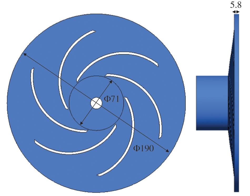
Figure 1: Calculation model of a low-specific-speed centrifugal pump impeller
3.2 Grid Independence Analysis
The structured hexahedral mesh of the impeller was created by GridPro software, as shown in Fig. 2. The number of grids will affect the results of numerical calculation [28], so a grid independence analysis was carried out. According to the grid independence verification procedure, there were six impeller models with different grid sizes: 150,000, 300,000, 540,000, 900,000, 2 million, and 3 million. Two typical working conditions of 0.25Qd and 1.0Qd were selected for the calculation. The variable Qd refers to the designed flow rate of the centrifugal pump. Fig. 3 illustrates the predicted head values under the designed condition and the minor flow rate condition of different grid numbers. In Table 2, as the number of grids increases, the head gradually decreases and tends to be stable. The test data from reference [25] was used to verify the model; the tested heads at 0.25Qd and 1.0Qd were 2.4 and 1.75 m, respectively. Comparing the test data and the numerical data, the calculation error under the designed condition was small, and the minimum error was 1.14%. On the other hand, the calculation error under minor flow rate conditions was relatively large, and the minimum error was 9.17%. Through grid independence and calculation error analyses, alongside the consideration of calculation accuracy and time, we selected 2 million grids as the final calculation model. The Y+ value of the calculated model was below 10.
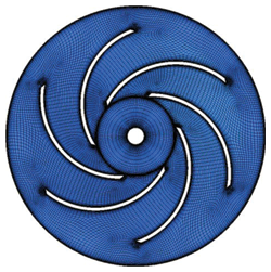
Figure 2: Schematic diagram of an impeller grid
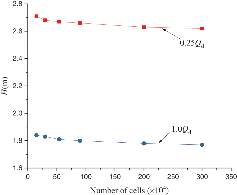
Figure 3: Grid independence analysis

3.3 Verification of the Numerical Results
This paper selected the numerical data at 1.0Qd and 0.25Qd to verify the accuracy of the numerical calculation results while taking PIV test data of this model from Reference [25]. In comparing PIV data, this study selected the relative velocities with radii of 0.5R2, 0.65R2, 0.75R2, 0.9R2, and 1.01R2 in the circumferential direction of the impeller’s middle section for analysis (Fig. 4).
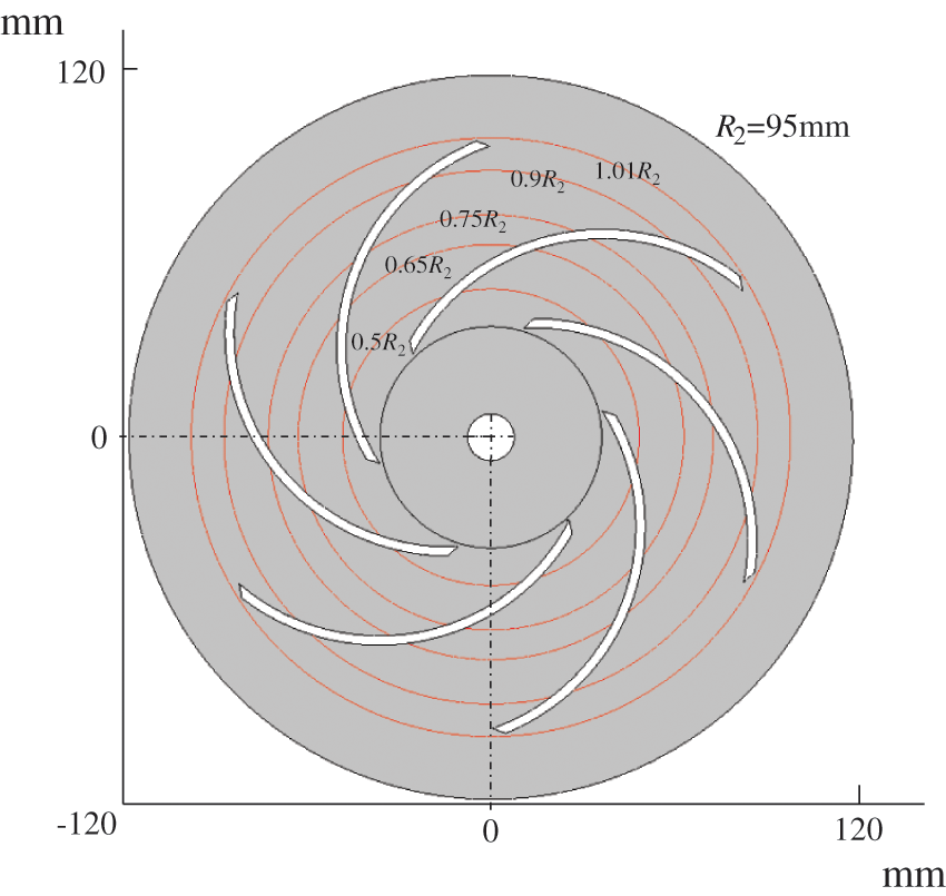
Figure 4: Distribution of relative velocity monitoring radius in the impeller
Fig. 5 depicts a comparison of PIV and CFD results at different monitoring radius. This paper found that: (1) Under the designed flow rate condition, the relative velocity distribution at different radii in the impeller was relatively uniform. The relative velocity in the impeller channel near the suction side was greater than the pressure side, and a jet-wake phenomenon occurred at the impeller exit. There was no noticeable difference in the relative velocity distribution of adjacent channels A and B. (2) Under minor flow rate conditions, the relative velocity distribution of the impeller channel A fluctuated wildly, and a large amount of backflow occurred near the inlet and outlet of the channel A, and the relative velocity distribution in the adjacent channel B was relatively uniform. Generally, LES could predict the relative velocity in the impeller flow passage more accurately.
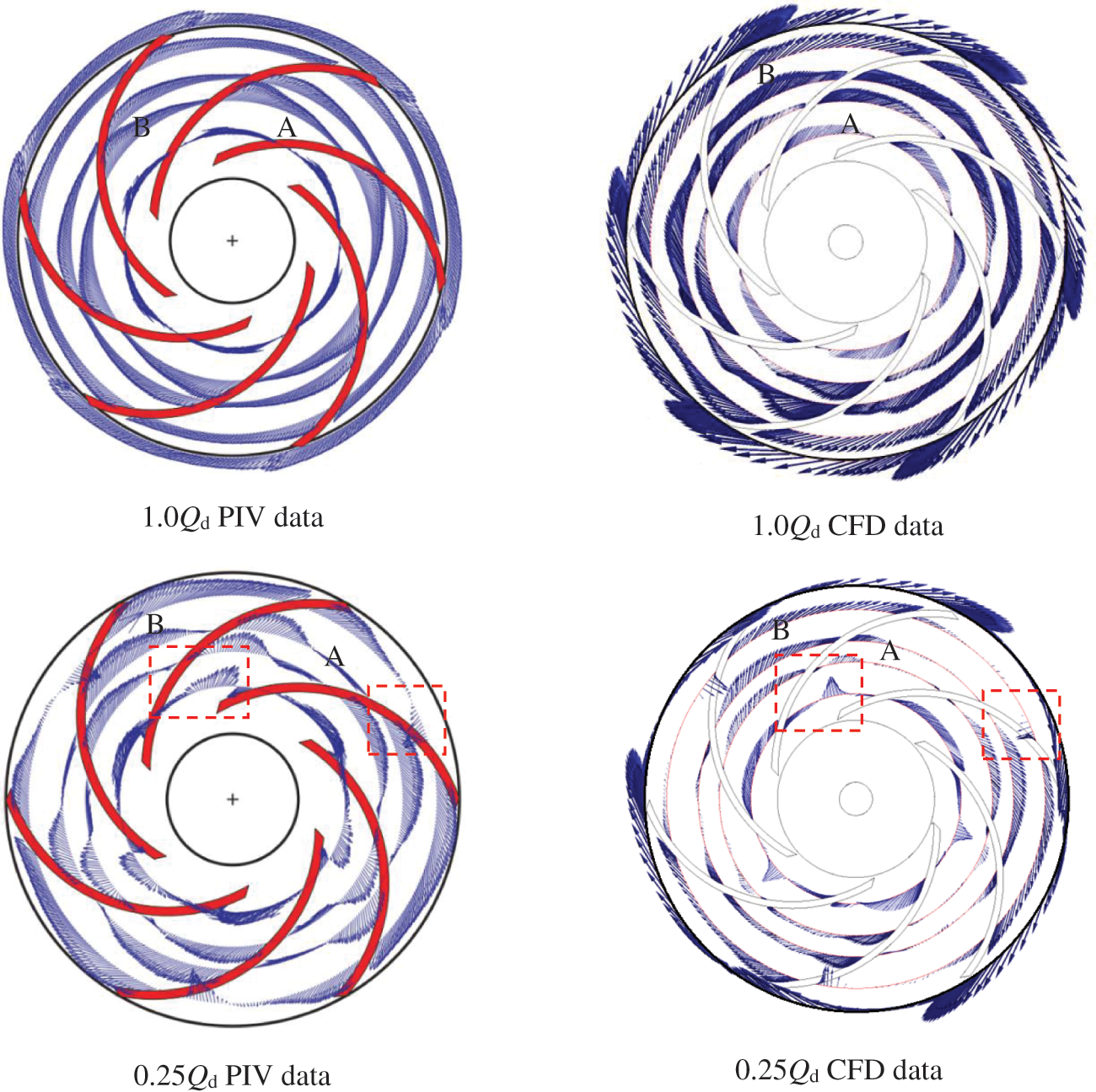
Figure 5: Comparison of relative velocity in the impeller
Figs. 6 and 7 illustrate the vorticity distribution of impeller at different flow rates in PIV and CFD. This paper found that: (1) Under designed flow rate conditions, the results of PIV and CFD determined that vortices were generated on the inlet side of the impeller and were distributed along the impeller flow passages near the suction side. It was because vorticity on the suction side of the impeller was higher than that on the pressure side. (2) Under a small flow rate, a large area of vortex emerged at the inlet of flow channel A of the impeller, which destroyed the flow pattern at the inlet of channel A. However, vorticity in adjacent flow channel B was lower, and the flow was relatively stable. Therefore, LES could predict the vorticity in the impeller flow passage more accurately.
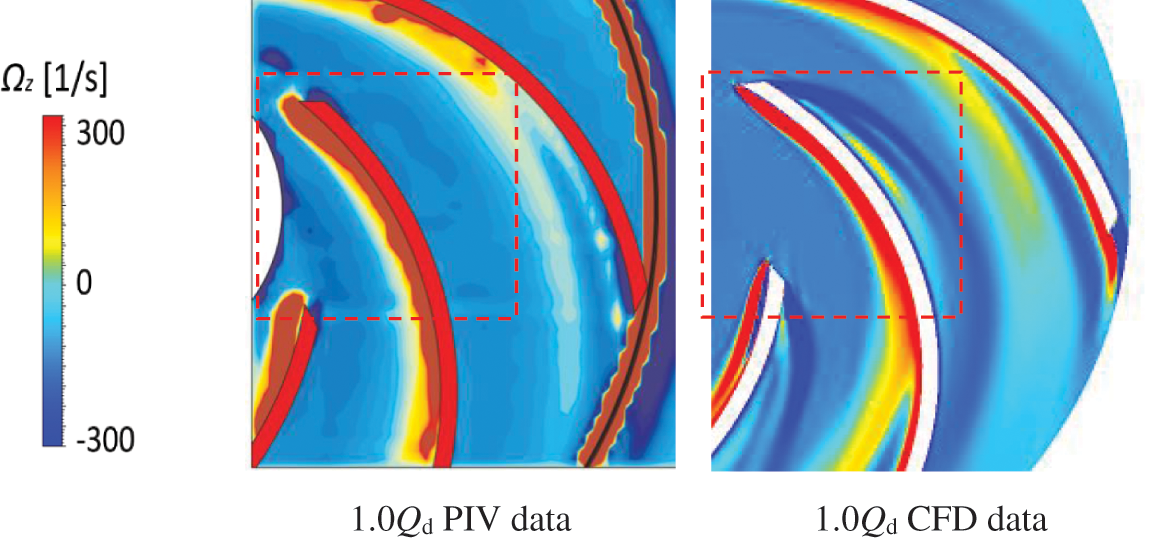
Figure 6: Comparison of impeller internal vorticity under the designed flow rate
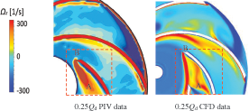
Figure 7: Comparison of impeller internal vorticity under a small flow rate
4 Evolution of Unsteady Flow in the Impeller
4.1 Evolution of Velocity Streamline in the Impeller
Fig. 8 illustrates the flow velocity streamlines in the impeller at different flow rates. This paper found that: (1) Under designed flow rate conditions, there was an even distribution in the velocity streamlines in the impeller, and the velocity on the suction side was more significant than that on the pressure side. No apparent vortex and flow separation were found in the entire impeller flow channel. (2) At 0.75Qd working condition, there was a difference between the liquid flow angle and the blade inlet angle, which formed a negative angle of attack. Then, it caused a local stall, which appeared on the suction side of the blade inlet. Meanwhile, flow separation began to appear on the pressure side of the blade. (3) At 0.5Qd working condition, due to the increase of the negative angle of attack, a large stall appeared at the inlet of impeller flow passages A, C, and E, which destroyed the inlet flow pattern impeller. On the pressure side, flow separation occurred and formed a local vortex near the middle of the pressure side of the blade. In contrast, the flow states in the adjacent channels B, D, and F were relatively stable. An apparent “alternating stall” phenomenon was observed in the impeller. (4) At 0.25Qd working condition, the vortices in the impeller channels A, C, and E further developed. Four large vortices appeared in one channel, while the flow in adjacent channels B, D, and F was still relatively stable.
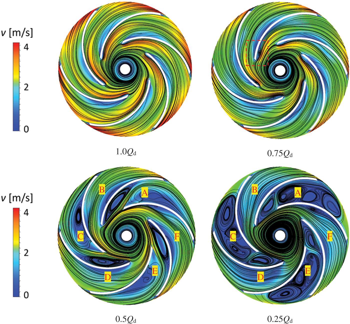
Figure 8: Evolution of velocity streamlines in the impeller under different flow rates
4.2 Evolution of Relative Velocity in Impeller
Fig. 9 shows the relative velocity of the impeller at different flow rates. This paper found that: (1) Under the designed flow rate condition, the relative velocity distribution in the impeller was uniform, and there was a certain degree of jet-wake phenomenon in both the impeller channel and the impeller outlet. (2) At 0.75Qd working condition, the jet-wake phenomenon in the impeller further enhanced. (3) At 0.5Qd working condition, due to the large area of stall vortices appearing at the inlet of the impeller channels A, C, and E, the relative velocity in the impeller fluctuated apparently. The impeller inlet had local backflow due to the effect of the stall. On the pressure side of the blade, due to the influence of local vortices, the relative velocity of the middle area of the impeller channel was near zero. In contrast, the relative velocity in adjacent channels B, D, and F was relatively stable. (4) At 0.25Qd working condition, the vortices in impeller flow passages A, C, and E further developed. Stalls blocked the entire flow passage. Backflow phenomena emerged at the inlet and outlet of the impeller. The flow state further deteriorated, and the flow state in the adjacent flow channel was relatively stable.
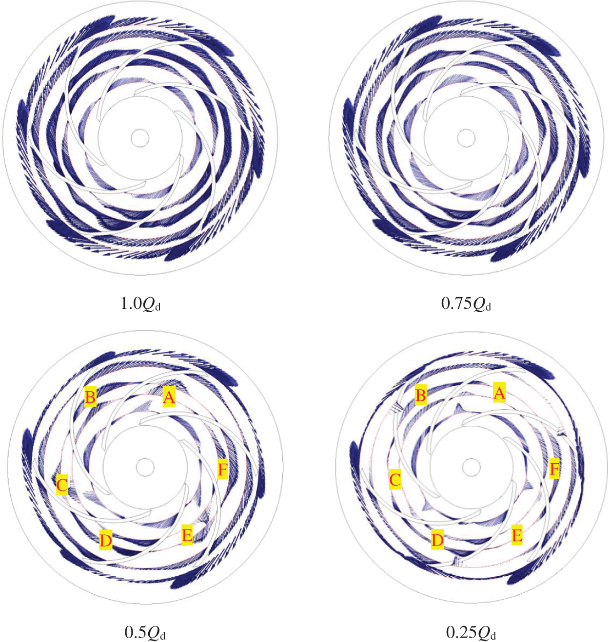
Figure 9: Evolution of relative velocity in the impeller under different flow rates
4.3 Evolution of Vorticity in the Impeller
Fig. 10 illustrates the vorticity distribution in the impeller under different flow rates. This paper found that: (1) At the designed flow rate, the vorticity of the impeller was small, then vorticity formed at the inlet edge of the blade and extended to the outlet of the blade. The vorticity distribution in each flow channel had a good consistency. (2) At 0.75Qd working condition, the change of the inlet impact angle made the vorticity at the inlet of the blade further increase. (3) At 0.5Qd working condition, under the influence of large stalls in the inlet of impeller flow channels A, C, and E, the vorticity extended toward the pressure side of the blade and gradually attenuated. In contrast, the vorticity of its adjacent flow channel (B, D, and F) was less. (4) At 0.25Qd working condition, the vortex of the impeller flow channel (A, C, and E) further developed and expanded, and local vorticity was generated in the inlet and blade pressure surface of the impeller, while the flow state in the adjacent flow was relatively stable.
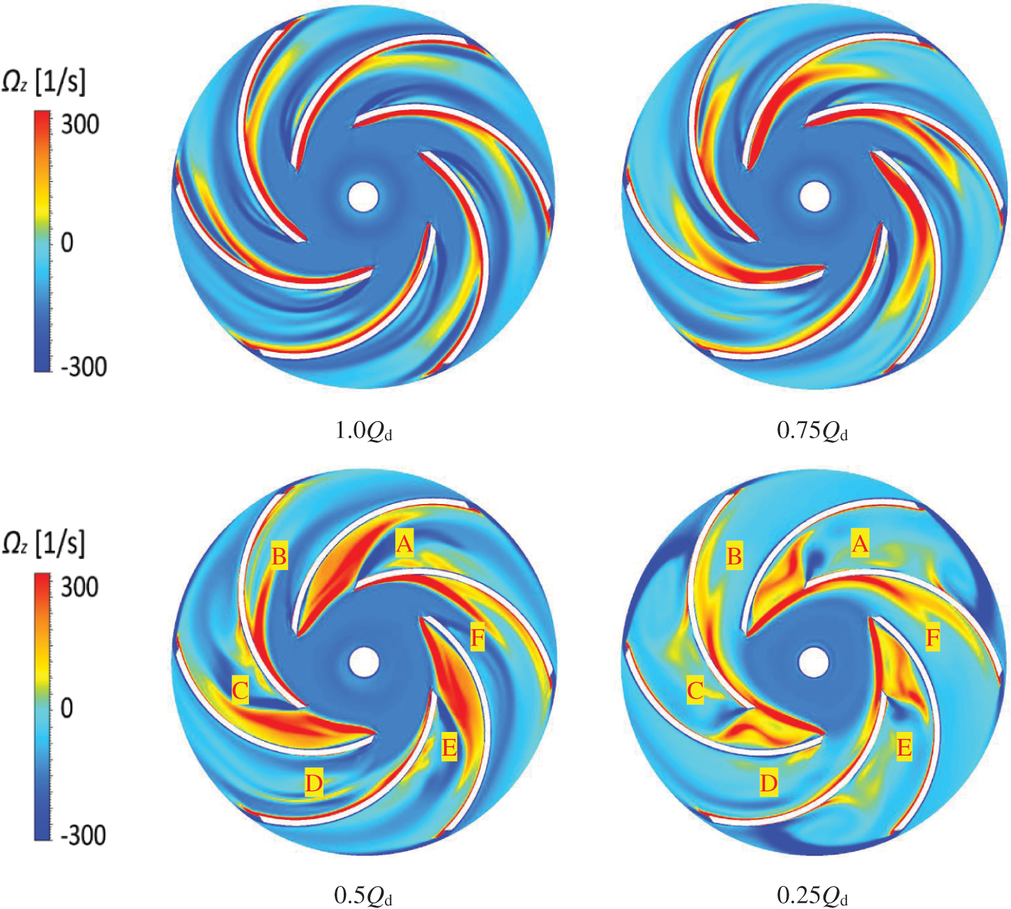
Figure 10: Evolution of vorticity in the impeller under different flow rates
LES studied the evolution of unstable flow inside the impeller, revealing the stall changes in the impeller under different working conditions. The main conclusions are as follows:
(1) Stall is generated near the suction surface of the blade inlet, moves in the circumferential direction to the pressure side of the blade, and gradually attenuates. As flow decreases, the number of stalls remains unchanged, while the occupied area and strength and the velocity along the circumferential direction increase.
(2) An apparent “alternating stall” phenomenon is observed in the impeller at low flow rate conditions. The significant deviation between flow and blade placement angle causes the vortex and flow separation in the impeller flow channels. As a result, a large stall size emerges at the inlet of impeller flow passages A, C, and E. Flow separation occurs and forms a local vortex near the middle of the pressure side of the blade. In contrast, flow states in adjacent channels B, D, and F are relatively stable.
(3) Under low flow rate conditions, the change of the inlet impact angle causes the vorticity at the inlet of the blade. The vorticity extends towards the pressure side of the blade along with flow rate decrease, while the vorticity in the adjacent flow is relatively small.
Funding Statement: This research was funded by the Zhejiang Provincial Natural Science Foundation of China (Grant Nos. LGG21E090002, LY21E060004, LGG21E090003), National Natural Science Foundation of China (Grant No. 51779226), the China Postdoctoral Science Foundation (Grant No. 2021M691383).
Conflicts of Interest: The authors declare that they have no conflicts of interest to report regarding the present study.
1. Sinha, M., Katz, J. (2020). Quantitative visualization of the flow in a centrifugal pump with diffuser vanes-I: On flow structures and turbulence. Journal of Fluids Engineering-Transactions of the ASME, 122(1), 97–107. DOI 10.1115/1.483231. [Google Scholar] [CrossRef]
2. Sinha, M., Katz, J., Meneveau, C. (2000). Quantitative visualization of the flow in a centrifugal pump with diffuser vanes-II: Addressing passage-averaged and large-eddy simulation modeling issues in turbomachinery flows. Journal of Fluids Engineering-Transactions of the ASME, 122(1), 108–116. DOI 10.1115/1.483232. [Google Scholar] [CrossRef]
3. Byskov, R. K., Jacobsen, C. B., Pedersen, N. (2003). Flow in a centrifugal pump impeller at design and off-design conditions–Part II: Large eddy simulations. Journal of Fluids Engineering-Transactions of the ASME, 125(1), 73–83. DOI 10.1115/1.1524586. [Google Scholar] [CrossRef]
4. Posa, A., Lippolis, A., Verzicco, R., Balaras, E. (2011). Large-eddy simulations in mixed-flow pumps using an immersed-boundary method. Computers & Fluids, 47(1), 33–43. DOI 10.1016/j.compfluid.2011.02.004. [Google Scholar] [CrossRef]
5. Gao, Z., Zhu, W., Lu, L., Deng, J., Zhang, J. G. et al. (2014). Numerical and experimental study of unsteady flow in a large centrifugal pump with stay vanes. Journal of Fluids Engineering-Transactions of the ASME, 136(7), 1–10. DOI 10.1115/1.4026477. [Google Scholar] [CrossRef]
6. Miorini, R. L., Wu, H., Katz, J. (2012). The internal structure of the tip leakage vortex within the rotor of an axial waterjet pump. Journal of Fluids Engineering-Transactions of the ASME, 134(3), 1–12. DOI 10.1115/1.4003065. [Google Scholar] [CrossRef]
7. Yang, W., Wang, F., Wang, H. (2012). Three-dimensional inverse problem optimization design of centrifugal fan blades. Journal of Agricultural Machinery, 43(8), 105–109. DOI 10.2514/6.2015-3931. [Google Scholar] [CrossRef]
8. Yang, W., Wang, F., Wang, H. (2012). Centrifugal impeller three-dimensional inverse problem design and numerical calculation. Journal of Drainage and Irrigation Machinery Engineering, 30(6), 632–635. DOI 10.3969/j.issn.1674-8530.2012.06.003. [Google Scholar] [CrossRef]
9. Zhu, Y., Wang, Z., Chen, H. (2012). Optimal design method of blade full three-dimensional inverse problem. Journal of Aerodynamics, 27(5), 1045–1052. DOI 10.13224/j.cnki.jasp.2012.05.015. [Google Scholar] [CrossRef]
10. Zhang, J., Zhu, H., Yang, C., Li, Y., Wei, H. (2011). Multi-objective shape optimization of helico-axial multiphase pump impeller based on NSGA-II and ANN. Energy Conversion and Management, 52(1), 538–546. DOI 10.1016/j.enconman.2010.07.029. [Google Scholar] [CrossRef]
11. Smagorinsky, J. (1963). General circulation experiments with the primitive equations. I. Basic Experiment. Monthly Weather Review, 91(3), 99–164. DOI 10.1175/1520-0493(1963)091<0099:GCEWTP>2.3.CO;2. [Google Scholar] [CrossRef]
12. Zhang, Z., Cui, G., Xu, C. (2008). Theory and application of turbulent large eddy simulation. Beijing: Tsinghua University Press. [Google Scholar]
13. Yang, Z. (2021). Research on large eddy simulation method of three-dimensional flow of centrifugal pump. Beijing: China Agricultural University. [Google Scholar]
14. Posa, A., Lippolis, A. (2018). A LES investigation of off-design performance of a centrifugal pump with variable-geometry diffuser. International Journal of Heat and Fluid Flow, 70(2), 299–314. DOI 10.1016/j.ijheatfluidflow.2018.02.011. [Google Scholar] [CrossRef]
15. Zhou, P. J., Wang, F. J., Yang, Z. J., Mou, J. G. (2017). Investigation of rotating stall for a centrifugal pump impeller using various SGS models. Journal of Hydrodynamics, 29(2), 235–242. DOI 10.1016/S1001-6058(16)60733-3. [Google Scholar] [CrossRef]
16. Posa, A. (2021). LES study on the influence of the diffuser inlet angle of a centrifugal pump on pressure fluctuations. International Journal of Heat and Fluid Flow, 89(2), 301–311. DOI 10.1016/j.ijheatfluidflow.2021.108804. [Google Scholar] [CrossRef]
17. Posa, A. (2021). LES investigation on the dependence of the flow through a centrifugal pump on the diffuser geometry. International Journal of Heat and Fluid Flow, 87(3), 225–231. DOI 10.1016/j.ijheatfluidflow.2020.108750. [Google Scholar] [CrossRef]
18. Huang, X. B., Liu, Z. Q., Li, Y. J., Yang, W., Gou, Q. (2019). Study of the internal characteristics of the stall in a centrifugal pump with a cubic non-linear SGS model. Journal of Hydrodynamics, 31(4), 229–234. DOI 10.1007/s42241-018-0170-y. [Google Scholar] [CrossRef]
19. Posa, A., Lippolis, A. (2018). A LES investigation of off-design performance of a centrifugal pump with variable-geometry diffuser. International Journal of Heat and Fluid Flow, 70(3), 321–329. DOI 10.1016/j.ijheatfluidflow.2018.02.011. [Google Scholar] [CrossRef]
20. Huang, X., Liu, Z., Yang, W. (2016). Numerical analysis of dynamic and static interference of centrifugal pump based on large eddy simulation. Chinese Science and Technology Paper, 11(19), 2256–2259. DOI 10.3969/j.issn.2095-2783.2016.19.021. [Google Scholar] [CrossRef]
21. Chao, W., Chen, W., Li, X., Xu, X., Song, S. S. et al. (2020). Unsteady large eddy simulation and experimental study of fuel centrifugal pumps. Hydraulics and Pneumatics, 12(4), 130–135. DOI 10.11832/j.issn.1000-4858.2020.04.021. [Google Scholar] [CrossRef]
22. Huang, X. B., Liu, Z. Q., Li, Y. J., Yang, W. (2018). Numerical investigation of flow features in the vaneless region of a centrifugal pump by large eddy simulation. Engineering Computations, 35(1), 125–134. DOI 10.1108/EC-09-2016-0328. [Google Scholar] [CrossRef]
23. Huang, S., Wu, Y. (2006). Large eddy numerical simulation of full three-dimensional flow field of centrifugal pump. Journal of South China University of Technology (Natural Science Edition), 15(4), 111–114. DOI 10.3321/j.issn:1000-565X.2006.04.024. [Google Scholar] [CrossRef]
24. Ye, D., Lai, X., Wang, Q., Zheng, H. (2019). Multi-objective optimization design of impeller blades of nuclear power plant reactor coolant pump based on genetic algorithm. Chinese Journal of Power Engineering, 39(8), 672–678. DOI CNKI:SUN:DONG.0.2019-08-011. [Google Scholar]
25. Han, K., Feng, Y. T., R., D. (2007). Numerical simulations of irregular particle transport in turbulent flows using coupled LBM-DEM. Computer Modeling in Engineering & Sciences, 18(2), 87–100. DOI 10.1016/j.chaos.2005.11.041. [Google Scholar] [CrossRef]
26. Miao, S., Zhang, H., Tian, W., Li, Y. Q. (2021). A study on the unsteady flow characteristics and energy conversion in the volute of a pump-as-turbine device. Fluid Dynamics & Materials Processing, 17(6), 1021–1036. DOI 10.32604/fdmp.2021.016925. [Google Scholar] [CrossRef]
27. Pedersen, N., Larsen, P. S., Jacobsen, C. B. (2003). Flow in a centrifugal pump impeller at design and off-design conditions–Part I: Particle image velocimetry (PIV) and laser Doppler velocimetry (LDV) measurements. Journal of Fluids Engineering-Transactions of the ASME, 125(1), 241–249. DOI 10.1115/1.1524585. [Google Scholar] [CrossRef]
28. Cheng, X., Liu, X., Lv, B. (2022). Influence of the impeller/guide vane clearance ratio on the performances of a nuclear reactor coolant pump. Fluid Dynamics & Materials Processing, 18(1), 93–107. DOI 10.32604/fdmp.2022.017566. [Google Scholar] [CrossRef]
 | This work is licensed under a Creative Commons Attribution 4.0 International License, which permits unrestricted use, distribution, and reproduction in any medium, provided the original work is properly cited. |