| Fluid Dynamics & Materials Processing |
DOI: 10.32604/fdmp.2022.020405
ARTICLE
An Improved Model to Characterize Drill-String Vibrations in Rotary Drilling Applications
School of Petroleum Engineering, China University of Petroleum (East China), Qingdao, 266580, China
*Corresponding Author: Hongjian Ni. Email: nihj@upc.edu.cn
Received: 21 November 2021; Accepted: 13 December 2021
Abstract: A specific model is elaborated for stick-slip and bit-bounce vibrations, which are dangerous dynamic phenomena typically encountered in the context of rotary drilling applications. Such a model takes into account two coupled degrees of freedom of drill-string vibrations. Moreover, it assumes a state-dependent time delay and a viscous damping for both the axial and torsional vibrations and relies on a sawtooth function to account for the cutting force fluctuation. In the frame of this theoretical approach, the influence of rock brittleness on the stability of the drill string is calculated via direct integration of the model equations. The results show that the rock brittleness has a great influence on the rotational speed and bit depth.
Keywords: Stick-slip vibration; bit bouncing; torsion pendulum; rock brittleness; cutting force
During drilling, the vibration of drill string in borehole mainly includes axial vibration, torsional vibration, and lateral vibration. The axial vibration is the bit-bounce, torsional vibration shows stick-slip vibration, lateral vibration is the collision between the bit and wellbore [1–5]. Because the contact force between bit and bottom hole is coupled to the friction between drill string and borehole, the interaction between drill string and borehole is highly nonlinear. So, it is difficult to study them in a same model [6].
The contact force between bit and rock is consist of cutting force and friction force. One of the factors affecting stick-slip vibration of drill string is the velocity nonlinearity of contact force [7–9]. Regardless of the uniform speed of the surface unit, the downhole drill string is bound to be unstable. It also affects the magnitude of the vibration. However, the coupling of axial vibration and torsional vibration is not considered in the above studies. The cutting force has both axial and tangential components, and its magnitude depend on the cutting depth. The cutting depth is determined by the axial vibration that produces the regenerative effect. The tangential components of the cutting force are combined to form the cutting torque, which becomes the lower boundary of the torsional vibration model of the drill string. Therefore, torsional vibration and axial vibration are coupled [9]. Compared with previous studies, Richard et al. [10] established a coupling model of axial and torsional vibration with constant friction coefficient. However, the model lacked axial stiffness, axial damping, and torsional damping, making steady-state drilling unstable under all conditions [11–13]. Besselink et al. [14] and Nandakumar et al. [12] added damping and axial stiffness to the above model to achieve stable under certain conditions. Nandakumar et al. [15] and Gupta et al. [9] studied a fully coupled two-degree-of-freedom model to analyze the stability of the system, in which the model assumes that both axial and torsional motions have state-dependent time delay and viscous damping.
Since rock brittleness has significant influence on the fluctuation of torque and the stability of drill string, saw teeth wave function is introduced into cutting force function to simulate rock brittleness. The influence of rock brittleness on the stability of drill string system is studied numerically.
2 A Two Degree-of-Freedom Axial-Torsional Model
Fig. 1 is the principal diagram of the 2 degree-of-freedom axial-torsional vibration model of drill string [9,15]. The torsional vibration model is simplified as a torsional pendulum, while the axial vibration model is simplified as a elastic-mass model. The moment of inertia of the drill pipe is combined with that of the Bottom Hole Assembly (BHA), represented by the lumped parameter I. The torsional stiffness of drill pipe is simplified as a linear elastic torsional stiffness Kt. The rotation speed of the top of drill string is assumed to be uniform rotation speed Ω0, and the rotation speed of the bit is represented by Ω. Torque T is generated by the tangential component of the bit-rock contact force acting on the moment of inertia I. Ca, Ct are the axial and torsional damping of the drill string, respectively.
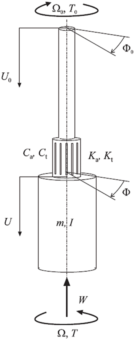
Figure 1: Schematic of the drill-string model with a lumped mass
The model ignores the axial yield of drill string and simplifies the BHA and drill string mass into lumped mass m. The axial stiffness of drill string is simplified as linear elastic stiffness Ka; the displacement at the top of the drill string is assumed to be uniform velocity U0, the displacement of bit is U. Weight on Bit (WOB) is the axial component W of the bit-rock contact force, which is applied to the axial lumped mass m. WOB and torque can be decomposed into cutting force and friction and are distinguished by their respective subscripts c and f. The cutting and friction components of W and T are derived from the single-tooth rock cutting experiment [16,17].
where:
where, a is the bit radius, d is the instantaneous depth of PDC teeth,
where
Therefore, the instantaneous cutting depth of a single blade (as shown in Fig. 2) is:
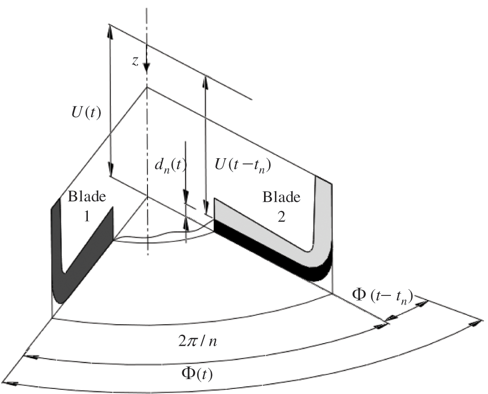
Figure 2: Schematic of the instantaneous cutting depth
where
The delay time
The total depth of n blades per revolution is:
When the bit rotates at a uniform speed, the speed is a constant value
Therefore, the dynamic differential equation of the drill string is shown as follows:
where:
W0 represents the effective WOB and is the negative of the bit-rock contact force, which is a drilling control parameter, and bit-rock contact force is negative of each other.
It should be noted that W0 and V0 are independent parameters. V0 can be expressed as follows:
where H(.) is Heaviside function,
sgn(.) is sgn function,
Since Tc in torsional dynamics model (8) and Wc in axial dynamics model (7) both contain instantaneous cutting depth d, the torsional dynamics model and axial dynamics model are coupled by parameter d. From the discontinuous equation H(.) and sgn(.). The bit-rock contact force of the bit still has discontinuous characteristics without considering brittleness.
3 Improvement of PDC Bit-Rock Contact Force Model
Richard et al.’s research [16] shows that the rock failure mode is related to the cutting depth: a ductile failure mode occurs in a shallow cutting. while a brittle failure mode occurs in a deep. To simplify the model, we ignore ductile failure cutting. According to the analysis of the model, the drilling model considers not only the axial and torsional elasticity of the drill string, but also the damping effect of drilling fluid. Due to the state-dependent-time-delay parameters, the drilling model is transformed into a two degree-of-freedom time-delay coupled dynamic model. However, the biggest problem of the model is that the brittleness of rock is not considered, which leads to no essential difference between the model and the metal cutting model, and the calculation results are greatly deviated from the actual situation.
For the convenience of numerical calculation, the following assumptions will be made in this paper:
①Ignore the clearance between adjacent cutters on the same blade.
②The arrangement of teeth of different blades is exactly the same.
③PDC teeth with the same distance from the axis of the bit belong to the same row. The PDC teeth closest to the axis of the bit are the first row, and the second row and the number as increases the distance. k is the number of the PDC teeth.
④The adjacent cutting teeth of the same blade do not affect each other in the cutting process.
⑤The fluctuation of cutting force is sawtooth.
Based on the above assumptions, the cutting torque Tck and cutting WOB Wck are generated by the Eq. (2):
In the process of PDC tooth cutting rock, the bulk cracking caused by rock brittleness is the main factor of its cutting force fluctuation. To simulate the fluctuation of cutting force [18,19], the cutting torque Tck and cutting WOB Wck are multiplied by a sawtooth function Sck. The torque Tck and Wck generated by the raw n tooth are expressed as follows:
According to references [20–24], the frequency of the fluctuation of cutting force depends on the following:
where, l is the crushing interval, d is the current cutting depth of the bit, ψ is the rock crushing angle. For rotary drilling, if the arc length of PDC teeth moving through the midpoint is taken as the cutting length, the breaking distance expression of the row k teeth is:
The wave function of cutting force of the row k can be expressed as:
where:
α1 is the bit rotation angle when the fluctuation of cutting force begins, and α is the current bit rotation angle. By combining (13) and (14), the cutting force expression of row k cutters can be obtained:
There are many ways to solve the vibration system. In this paper, the direct integration method is used to solve the equation from the physical equation, without solving the inherent characteristics of the equation, and without decoupling the equation. In general, the direct integration method firstly discretizes the time with equal interval method, and only satisfies the motion differential equation at time points after discretization, and there is no requirement between time points. Secondly, the first discrete point is integrated according to the discrete incremental equilibrium equation in the time interval, and then the following points are integrated step by step. In the process of integration, different calculation methods can be obtained according to different assumptions. These methods have different convergence and stability. The commonly used methods mainly include linear acceleration method, Wilson-θ method, etc. In this paper, linear acceleration method is adopted.
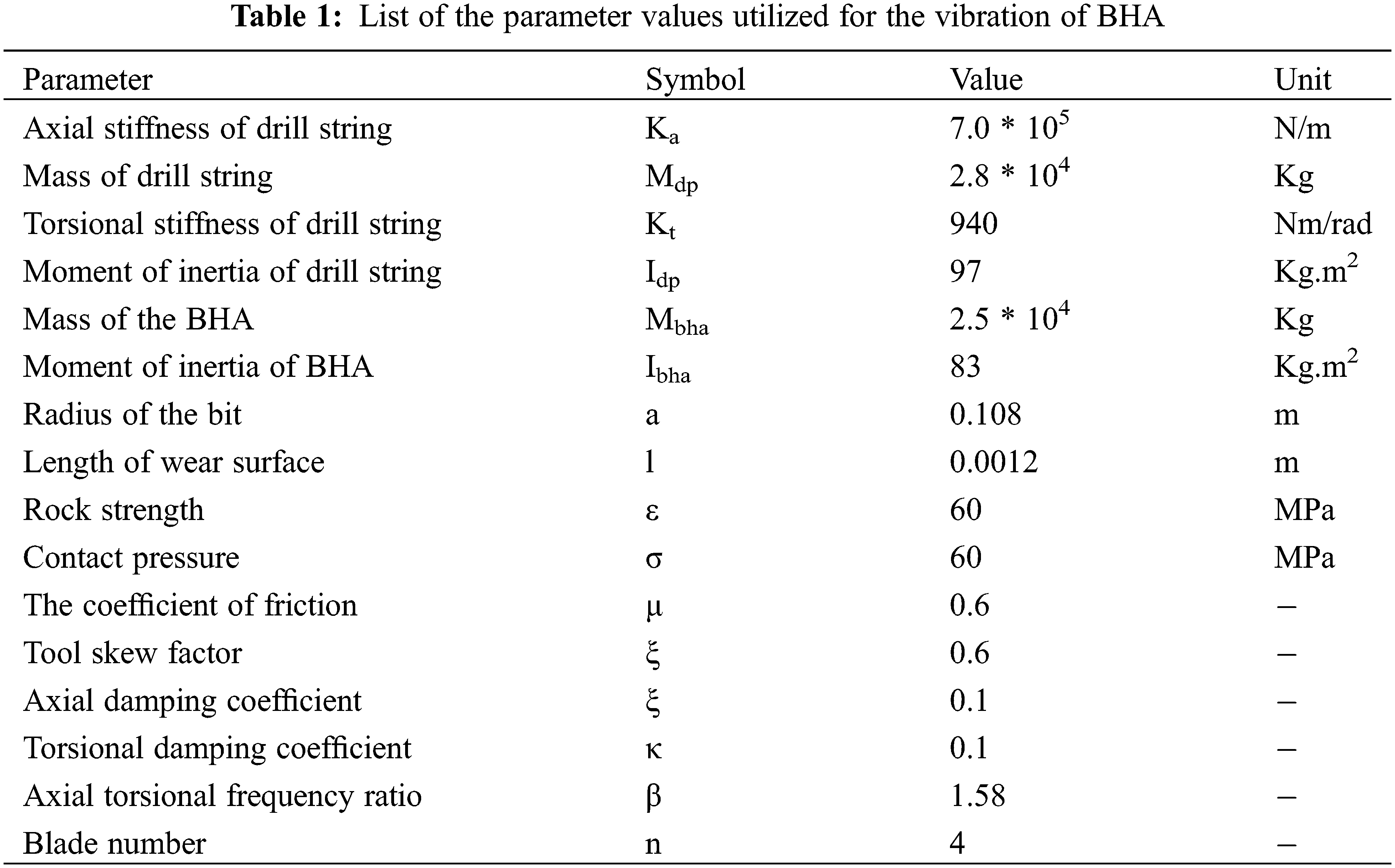
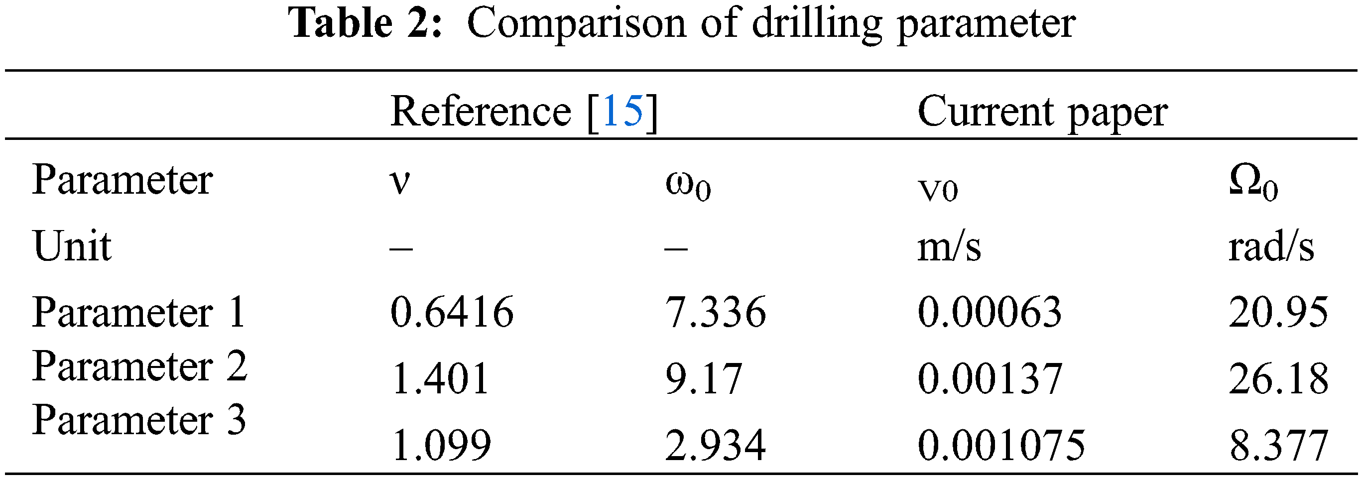
Parameters required for calculation are shown in Table 1. According to reference [15], the rock breakage angle φ ranges from 125° to 142°, and the breakage angle is set as 135° in this paper. The drilling parameters were dimensionless and divided into stable zone (no stick-slip vibration and axial vibration) and unstable zone. Three groups of data, point 1 in the stable zone, point 2 and point 3 in the unstable zone, were selected for numerical simulation.
When t < 0, the initial drilling state is set as uniform drilling. We are going to increase our average velocity by 10% at t = 0. This initial state is arbitrarily set and represents a velocity disturbance for stable drilling. The expression of initial conditions is shown in (19)–(22):
There is a process of entering and exiting stick-slip vibration in the process of numerical calculation. Assume the current time step is i, then the displacement of bit is Ui, the axial velocity of bit Vi.
Enter torsional stick:
If Φi = Φi-1, the bit enters torsional stick. Then Ui = 0, Vi = 0.
Exit torsional stick:
The model will automatically exit torsional stick.
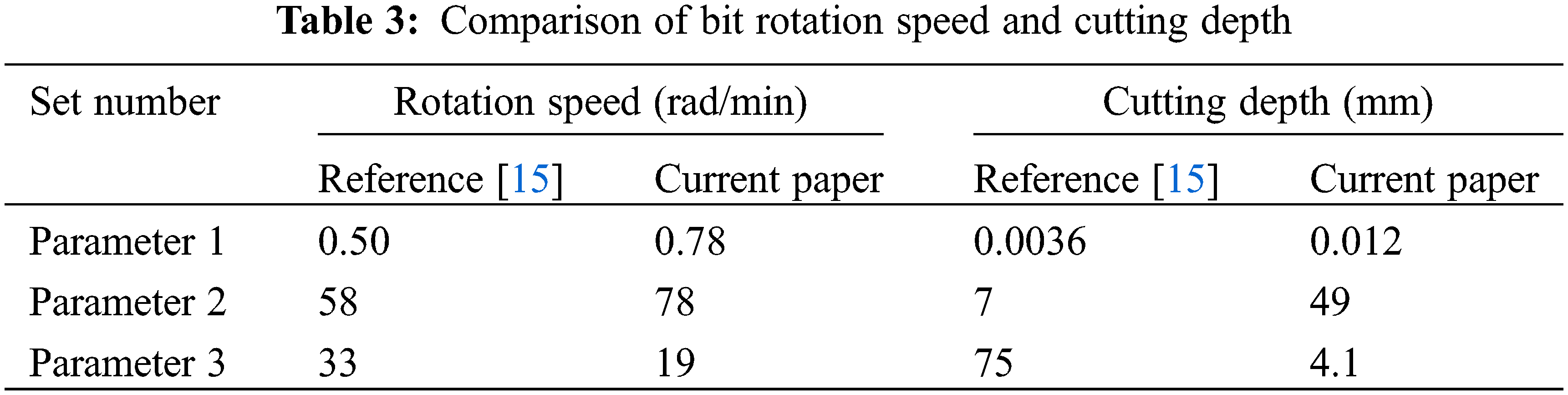
The comparison of calculation results between the original model and the improved model is shown in Figs. 3 and 4, the drilling parameter is shown in Table 2, and the amplitude of rotation speed and cutting depth fluctuation is shown in Table 3. For drilling parameter 1 located in the steady-state region of the original model, the fluctuation amplitude of rotation speed and cutting depth of the improved model is slightly larger than that of the original model. Drilling parameter 2 was in the stick-slip zone of the original model, and the improved model increased the amplitude of rotation velocity by 34% and the amplitude of cutting depth by 600% compared to the original model. The drilling parameter 3 was in the stick-slip zone of the original model, and the fluctuation amplitude of the rotation velocity was reduced by 42% and the fluctuation amplitude of the cutting depth was reduced by 95% compared with the original model.
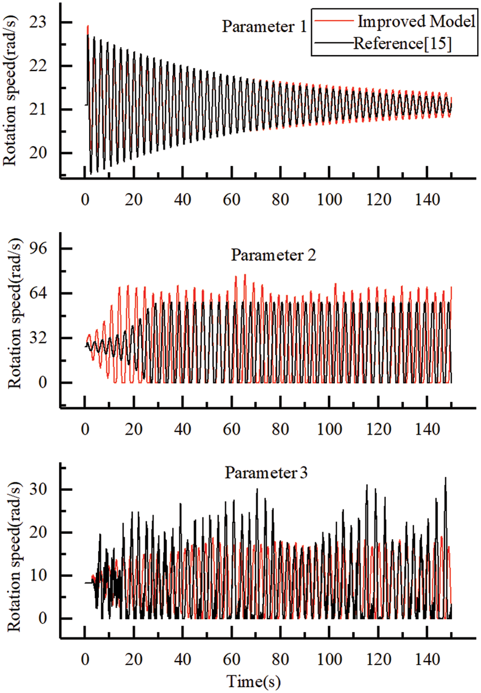
Figure 3: Comparison of the bit rotation speed
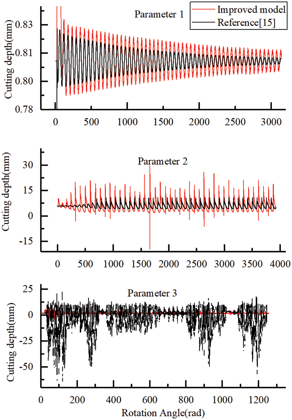
Figure 4: Comparison of cutting depth
In this paper, a lot of numerical simulation is carried out based on the improved model, and the parameter boundary of stationary drilling in ω0-v plane is determined. The comparison results are shown in Fig. 5. The stationary region of the model in [15] is mainly the region contained between the blue line and v = 0. The stationary drilling parameters of the improved model are mainly concentrated in the zone surrounded by the red line. One of the differences between the two stationary regions is the region close to v = 0. it is the stationary region in the model of [15], while it is not the stationary region in the improved model. According to the drilling parameters in the field, it is unstable in the region near v = 0, which shows that the improved model is more accurate. The improved model’s stationary drilling parameters are zonal and more like the experimental results.
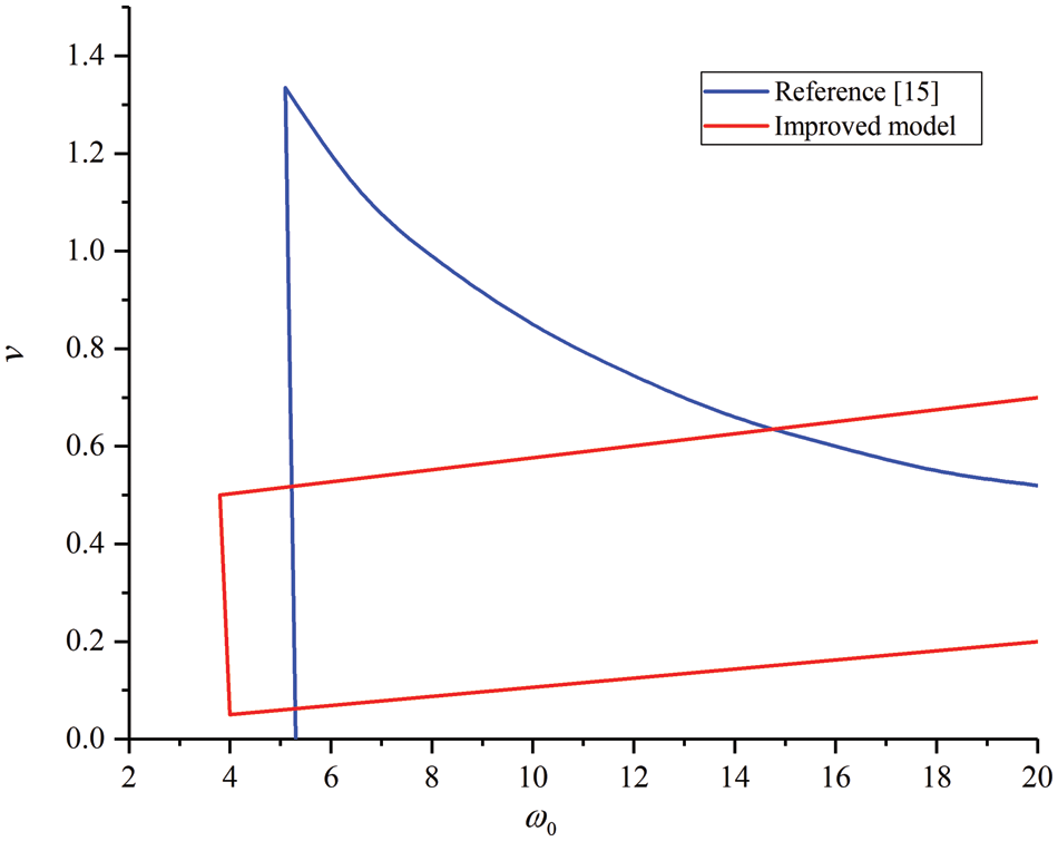
Figure 5: Comparison of the stationary region of drilling parameters
The method in this paper is verified by the experimental equipment in reference [23]. We will verify the point ω0 = 6 and v = 1 in ω0-v plane. Experimental parameters are V0 = 0.98 mm/s, Ω0 = 17.13 rad/s. The experimental results are shown in Figs. 6 and 7. Stick-slip vibration and bit-bounce occurred. The model in this paper predicts stick slip and bit-bounce, while the model in reference [15] does not.
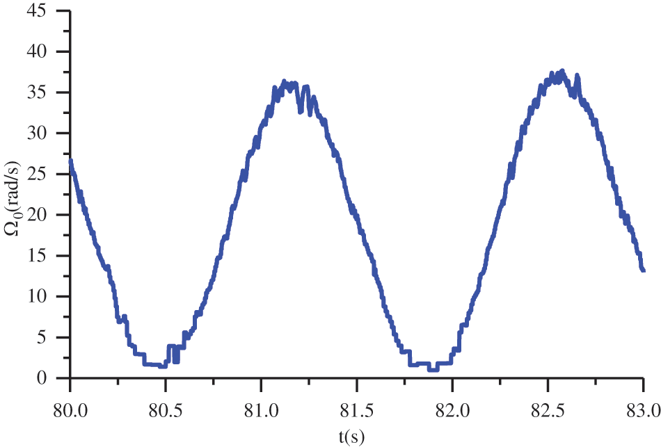
Figure 6: Bit rotation speed
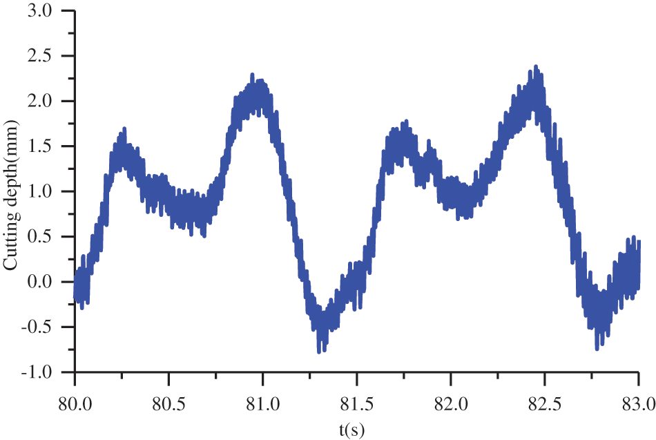
Figure 7: Cutting depth
(1) The analysis of the calculated results show that brittleness leads to the increase of the amplitude of rotation velocity and cutting depth of parameter 1 and parameter 2; Brittleness results in reduced fluctuation of rotation speed and cutting depth of parameter 3.
(2) The brittleness of rock affects not only the fluctuation amplitude of rotation speed and cutting depth, but even the motion state of the bit. The parameter 2 is stick-slip only in the original model, while stick-slip and bit bouncing are shown in the improved model.
(3) The improved model’s stationary drilling parameters are zonal, and it is much more different from the original model and more like the field results.
Rock brittleness is an important factor affecting the motion state of drill bit. It can improve the accuracy of model calculation and provide a reference for the selection of drilling parameters.
Funding Statement: This work was sponsored by the Major Science and Technology Project of the CNPC under Grant ZD2019-183-005.
Conflicts of Interest: The authors declare that they have no conflicts of interest to report regarding the present study.
1. Xu, Y., Zhang, H., Guan, Z. (2021). Dynamic characteristics of downhole bit load and analysis of conversion efficiency of drill string vibration energy. Energies, 14(1), 229. DOI 10.3390/en14010229. [Google Scholar] [CrossRef]
2. Tian, J., Yang, Y., Yang, L. (2017). Vibration characteristics analysis and experimental study of horizontal drill string with wellbore random friction force. Archive of Applied Mechanics, 87(9), 1439–1451. DOI 10.1007/s00419-017-1262-9. [Google Scholar] [CrossRef]
3. Arjun Patil, P., Teodoriu, C. (2013). Model development of torsional drillstring and investigating parametrically the stick-slips influencing factors. Journal of Energy Resources Technology, 135(1), 032802. DOI 10.1115/1.4007915. [Google Scholar] [CrossRef]
4. Wiercigroch, M., Nandakumar, K., Pei, L., Kapitaniak, M., Vaziri, V. (2017). State dependent delayed drill-string vibration: Theory, experiments and new model. Procedia IUTAM, 22(2), 39–50. DOI 10.1016/j.piutam.2017.08.007. [Google Scholar] [CrossRef]
5. Zheng, X., Balachandran, B. (2017). State-dependent delay and drill-string dynamics. Procedia IUTAM, 22(3), 31–38. DOI 10.1016/j.piutam.2017.08.006. [Google Scholar] [CrossRef]
6. Ghasemloonia, A., Rideout, D. G., Butt, S. D. (2015). A review of drillstring vibration modeling and suppression methods. Journal of Petroleum Science and Engineering, 131(10), 150–164. DOI 10.1016/j.petrol.2015.04.030. [Google Scholar] [CrossRef]
7. Challamel, N., Sellami, H., Chenevez, E., Gossuin, L. (2000). A stick/slip analysis based on rock/bit interaction. Journal of Petroleum Technology, 52(12), 30–31. DOI 10.2118/1200-0030-JPT. [Google Scholar] [CrossRef]
8. Kyllingstad, A., Halsey, G. W. (1988). A study of slip/stick motion of the bit. SPE Drilling Engineering, 3(4), 369–373. DOI 10.2118/16659-PA. [Google Scholar] [CrossRef]
9. Gupta, S. K., Wahi, P. (2016). Global axial-torsional dynamics during rotary drilling. Journal of Sound and Vibration, 375(3), 332–352. DOI 10.1016/j.jsv.2016.04.021. [Google Scholar] [CrossRef]
10. Richard, T., Germay, C., Detournay, E. (2007). A simplified model to explore the root cause of stick–slip vibrations in drilling systems with drag bits. Journal of Sound and Vibration, 305(3), 432–456. DOI 10.1016/j.jsv.2007.04.015. [Google Scholar] [CrossRef]
11. Challamel, N., Sellami, H., Chenevez, E., Gossuin, L. et al. (2000). A stick-slip analysis based on rock/bit interaction: Theoretical and experimental contribution. IADC/SPE Drilling Conference, OnePetro. [Google Scholar]
12. Nandakumar, K., Wiercigroch, M. (2013). Galerkin projections for state-dependent delay differential equations with applications to drilling. Applied Mathematical Modelling, 37(4), 1705–1722. DOI 10.1016/j.apm.2012.04.038. [Google Scholar] [CrossRef]
13. Wang, P., Ni, H., Wang, R., Li, Z., Wang, Y. (2016). Experimental investigation of the effect of in-plane vibrations on friction for different materials. Tribology International, 99(9), 237–247. DOI 10.1016/j.triboint.2016.03.021. [Google Scholar] [CrossRef]
14. Besselink, B., van de Wouw, N., Nijmeijer, H. (2011). A semi-analytical study of stick-slip oscillations in drilling systems. Journal of Computational and Nonlinear Dynamics, 6(2), 235. DOI 10.1115/1.4002386. [Google Scholar] [CrossRef]
15. Nandakumar, K., Wiercigroch, M. (2013). Stability analysis of a state dependent delayed, coupled two DOF model of drill-stringvibration. Journal of Sound and Vibration, 332(10), 2575–2592. DOI 10.1016/j.jsv.2012.12.020. [Google Scholar] [CrossRef]
16. Richard, T., Detournay, E., Drescher, A., Nicodeme, P., Fourmaintraux, D. et al. (1998). The scratch test as a means to measure strength of sedimentary rocks. In: SPE/ISRM rock mechanics in petroleum engineering. OnePetro. [Google Scholar]
17. Detournay, E., Defourny, P. (1992). A phenomenological model for the drilling action of drag bits. International Journal of Rock Mechanics and Mining Sciences & Geomechanics Abstracts, 29, 13–23. [Google Scholar]
18. Munoz, H., Taheri, A., Chanda, E. (2016). Rock cutting characteristics on soft-to-hard rocks under different cutter inclinations. International Journal of Rock Mechanics and Mining Sciences, 100(87), 85–89. DOI 10.1016/j.ijrmms.2016.05.014. [Google Scholar] [CrossRef]
19. Wang, Y., Ni, H., Wang, R., Huang, B., Liu, S. et al. (2022). Numerical simulation research on cutting rock with a PDC cutter assisted by an impact force. Advances in Civil Engineering, 2022(1), 1–9. DOI 10.1155/2022/8282104. [Google Scholar] [CrossRef]
20. de Moraes, L. P., Savi, M. A. (2019). Drill-string vibration analysis considering an axial-torsional-lateral nonsmooth model. Journal of Sound and Vibration, 438(9), 220–237. DOI 10.1016/j.jsv.2018.08.054. [Google Scholar] [CrossRef]
21. Aarsnes, U. J. F., van de Wouw, N. (2019). Axial and torsional self-excited vibrations of a distributed drill-string. Journal of Sound and Vibration, 444, 127–151. DOI 10.1016/j.jsv.2018.12.028. [Google Scholar] [CrossRef]
22. Real, F. F., Batou, A., Ritto, T. G., Desceliers, C. (2019). Stochastic modeling for hysteretic bit-rock interaction of a drill string under torsional vibrations. Journal of Vibration and Control, 25(10), 1663–1672. DOI 10.1177/1077546319828245. [Google Scholar] [CrossRef]
23. Wang, Y., Ni, H., Tu, Y. P., Wang, R., Wang, X. et al. (2021). Experimental study on axial impact mitigating stick-slip vibration with a PDC bit. Shock and Vibration, 2021, 1–8. DOI 10.1155/2021/8897283. [Google Scholar] [CrossRef]
24. Wang, Y., Ni, H., Wang, R., Lei, P., Huang, B. et al. (2021). Effect of pulsed jet on pore pressure of deep formation rock. Shock and Vibration, 2021, 1–9. DOI 10.1155/2021/2217787. [Google Scholar] [CrossRef]
 | This work is licensed under a Creative Commons Attribution 4.0 International License, which permits unrestricted use, distribution, and reproduction in any medium, provided the original work is properly cited. |