| Fluid Dynamics & Materials Processing |
DOI: 10.32604/fdmp.2022.021827
ARTICLE
Experimental Electromagnetic Characterization of High Temperature Superconductors Coils Located in Proximity to Electromagnetically Active Materials
Université de Lorraine, GREEN, Nancy, F-54000, France
*Corresponding Author: Hocine Menana. Email: hocine.menana@univ-lorraine.fr
Received: 07 February 2022; Accepted: 25 February 2022
Abstract: The electromagnetic properties of high temperature superconductors (HTS) are characterized with the explicit intent to improve their integration in electric power systems. A tape and a coil made of Bismuth Strontium Calcium Copper Oxide (BSCCO) are considered in the presence of electromagnetically active materials in order to mimic properly the electromagnetic environment typical of electrical machines. The characterization consists of the determining the critical current and the AC losses at different values of the frequency and the transport current. The effects induced by the proximity of the active materials are studied and some related experimental issues are analyzedc.
Keywords: AC losses; HTS coils; experimental characterization; proximity of electromagnetically active materials
Nomenclature
| U | Voltage [V] |
| I | Electric current [A] |
| E | Electric field [V/m] |
| J | Electric current density [A/m2] |
| Uc | Critical voltage [V] |
| Ec | Critical electric field [V/m] |
| Ic | Critical current [A] |
| Jc | Critical current density [A/m2] |
| n | Creep exponent characterizing the steepness of the transition from the superconductive to the normal state |
| Lt | Tape length [m] |
| St | Tape thickness [m] |
| Ulosses | Voltage in phase with the current [V] |
| L | Self-inductance of the superconductor [H] |
| M | Mutual inductance of the superconductor [H] |
| P | Average AC losses [W] |
| Irms | RMS value of the current [A] |
| U1rms | RMS value of the fundamental of the voltage signal [V] |
| φ1 | Phase shift between the fundamental of the voltage and the current [rad] |
| Te | Sampling period [s] |
| T | Period [s] |
Superconductors have exceptional electromagnetic properties [1]. Research in this field has been in constant evolution both on theoretical aspects, for the understanding of physical phenomena, and on their applications, in particular, the integration of high temperature superconductors (HTS) in electrical power systems. Indeed, HTS are particularly good candidates for the development of more compact and more efficient electrical machines, in particular for renewable energies and aerospace applications [2–4]. However, the integration of HTS in electrical power systems remains very limited, especially in electrical machines, where they are used only as inductors or for the magnetic field screening in synchronous machines [5,6]. Fully HTS machines concepts are not yet mature [7,8]. The reasons are not only related to the technical constraints of manufacturing HTS, but also to the ignorance of the behavior of such materials in a complex electromagnetic environment. Indeed, the critical current and losses in HTS are strongly dependent on the electromagnetic environment. The characterization of their physical properties is therefore crucial [9–13]. However, the characterization of HTS is a difficult task, due to their unconventional properties characterized by anisotropies and non-linearities. The strong and nonlinear dependence of their electrical properties to the magnetic field makes the transition from the sample characterization to the system a nontrivial task. Indeed, the critical current density in HTS strongly depends on the magnetic field strength and orientation [14,15]. Therefore, the shape of the HTS element and the proximity of electromagnetically active materials affect considerably its performances.
In this context, this work is a contribution to the characterization of tapes and coils made of Bismuth Strontium Calcium Copper Oxide (BSCCO) based HTS material, produced by Sumitomo Electric [16]. The characterization is done in both DC and AC regimes, in the proximity of active materials, aiming to reproduce their electromagnetic environments when they are used in electrical machines. In the DC characterization the voltage dependence on the current “U(I)” is determined for a tape and a coil in different configurations. The AC losses are then measured for a coil in the self-field condition, and with the proximity of ferromagnetic materials, highlighting the effect of the proximity such materials on the losses in HTS coils. This is the main contribution of this work to the state of the art of the HTS characterization. A method of losses separation is applied, to extract the AC losses in the HTS from the measured losses including the iron losses in the ferromagnetic material [17,18]. We also highlight some problems encountered in the experimental characterization and their resolution.
The characterization methods are presented in the next section, followed by the presentation of the main obtained results and their interpratation.
2 DC and AC Characterization Methods
With the assumption that the electric current (I) is uniform in the section of the tape, the E(J) relation, i.e., the electric field (E) dependence on the electric current density (J), is deduced from the U(I) curves measurement, i.e., the voltage dependence on the electric current, in the superconductive element.
The four-point measurement method is used for the determination of the U(I) curves [5]. The element is supplied by a direct current I, and the potential difference U across its terminals is measured (Fig. 1). The measurement points must be far from the current leads to avoid the perturbation voltage generated by the Seebeck effect due to the temperature gradient in this region. The critical electric field is: Ec = 1 μV/cm. The critical voltage (Uc) of the sample is the product of the critical electric field “Ec” with the tape length “Lt” between the points of the potential measurement (Uc = Ec × Lt), and the critical current (Ic = Jc × St), where St is the tape section, is the current giving this critical voltage. The E(J) or U(I) dependence is generally expressed by the power law given by Eq. (1), where n is the creep exponent characterizing the steepness of the transition from the superconductive to the normal state.
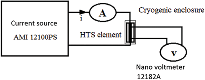
Figure 1: The U(I) curves measurement system [13]
Fig. 2 shows the test bench for the measurement of AC losses using a synchronous detection [9,10]. The superconductive element is fed by a sinusoidally varying current from an AC current source in which both the amplitude and frequency are variable. An isolation transformer is used to avoid electromagnetic disturbances passing through the mass. The measurement at the network frequency is not recommended, since it can be very disturbed.
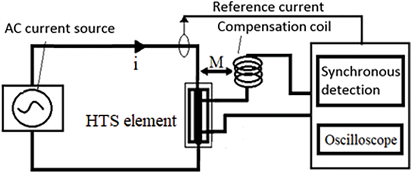
Figure 2: The AC losses measurement system [13]
The voltage measured across the element contains a resistive part which is in phase with the current and responsible for the losses, and an inductive part which is a few hundred times higher than the resistive part which is of interest. The measurement of the inductive part has been compensated to avoid to calibrate the apparatus its voltage level leading to considerable errors in the measurement of the resistive part which would be embedded in its error margin. We used a compensation coil connected in series with the measurement wires, and positioned near the power supplying cable (Fig. 2). The compensation coil orientation is chosen so that the mutual inductance (M) with the supplying cable is in opposition with the inductance (L) of the tested element. The measured voltage is then given as follows [13]:
The distance separating the compensation coil and the supplying cable is varied such as the mutual inductance (M) becomes in the same order as the self-inductance (L) of the characterized sample. There is no need to eliminate completely the inductive part; it is sufficient to bring it to a value close to the resistive part (Ulosses). The reference in the synchronous detection is the supply current signal. The signal form of the measured voltage is non-sinusoidal due to the non-linear behavior of the superconductor, related to the nonlinear dependence of the electric field on the electric current (Eq. (1)). The AC losses are only linked to the fundamental of this voltage, given by Eq. (3), where, Irms, U1rms, and φ1 denote respectively the RMS of the current, the RMS of fundamental of the voltage signal, and the phase shift between them.
The main disadvantage of this method is that it only works if the reference signal is sinusoidal. For other forms of current, one can use a numerical integration on an oscilloscope, as follows, where Te is the sampling period and T = N × Te:
The DI-BSCCO (dynamically innovative BSCCO) type tape, manufactured by Sumitomo Electric [16] has been used. Such tape is composed of twisted BSCCO filaments in a silver matrix. The specifications of the characterized elements (tape and coil) are given in Table 1. The measurements were all done at the temperature of liquid nitrogen (77 K). Concerning the HTS coil, in order to study the influence of the proximity of magnetically active materials, three configurations are considered as shown in Fig. 3: in self-field (Case (a)), in presence of a ferromagnetic plate (Case (b)), and in presence of a NdFeB permanent magnet (Case (c)).

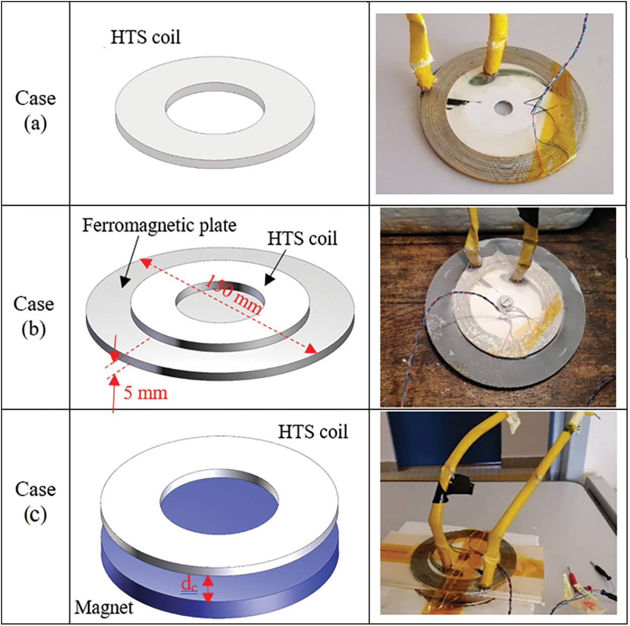
Figure 3: The studied configurations: (a) HTS coil considered alone, (b) HTS coil above a ferromagnetic plate, (c) HTS coil above a NdFeB magnet
The U(I) curves measured for the tape in self-field is given in Fig. 4. The measured results are perfectly fitted by the power law (Eq. (1)) with a creep exponent n = 11. The identified critical current is Ic = 69.5 A, while the data provided by the constructor announce a value of 70 A. This difference may be due to an aging of the material over time.
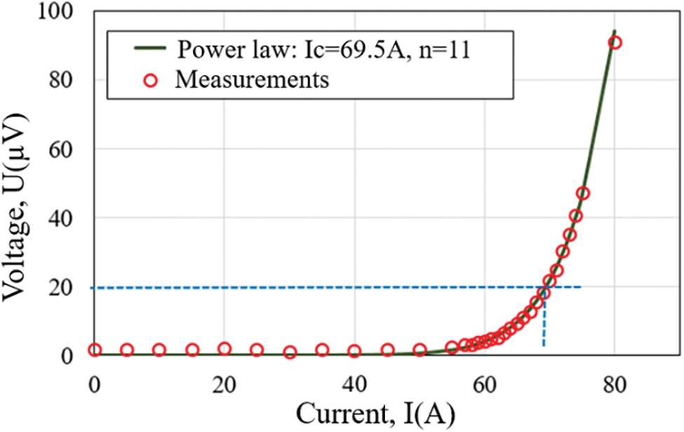
Figure 4: Measured U(I) curve for the tape and its interpolation by the power law
The U(I) curves measured for the coil for the configurations described in Fig. 3 are presented in Fig. 5. The obtained critical current in the self-field (Case (a)) is lower than that of the tape, highlighting the effect of the HTS coil geometry on its superconducting performances. Indeed, the self-magnetic field in the coil is greater than that of the tape. The proximity of the ferromagnetic plate increases the values of the magnetic field and introduces a supplementary degradation of the critical current of the HTS coil. Finally, the exposition to the magnetic field generated by NdFeB magnet (Case (c)) decrease dramatically the critical current of the HTS coil, since this magnetic field is of high value and whose component perpendicular to the widest surface of the tape (the most influential) is high [13].
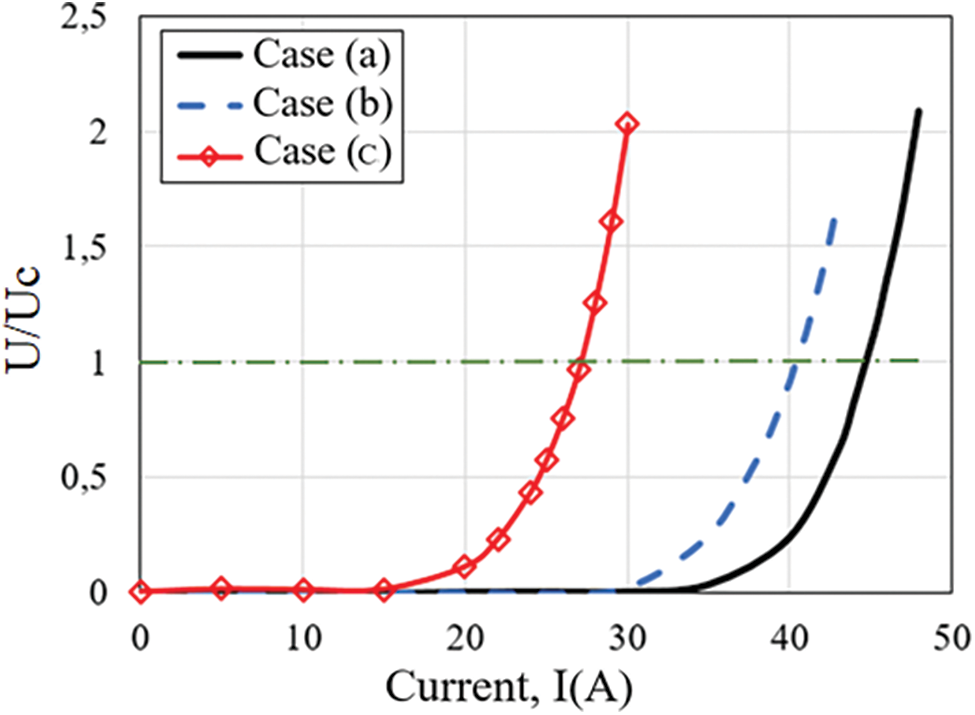
Figure 5: Measured U(I) curve for the configurations presented in Fig. 3
Figs. 6 and 7 show the measured current and voltage with and without using the compensating coil. As the inductive part is largely predominant, the measured voltage without compensation seems to be sinusoidal in quadrature of phase with respect to the current signal. It is also of relatively high value (in the order of volt). With the coil inductance compensation, the measured voltage is of much lower value (in the order of millivolts), and presents a non-sinusoidal form, due to the nonlinear electrical properties of the superconductive material. The fundamental of the measured voltage signal is in phase with the current signal.
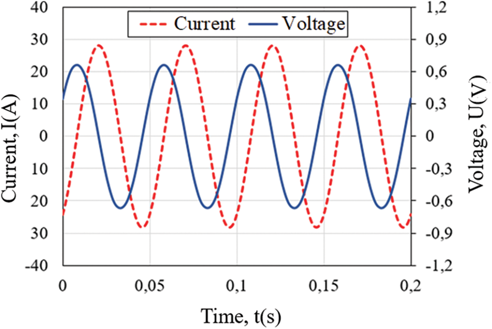
Figure 6: Measured voltage and current without compensation (Case (a), Irms = 20 A, f = 20 Hz)
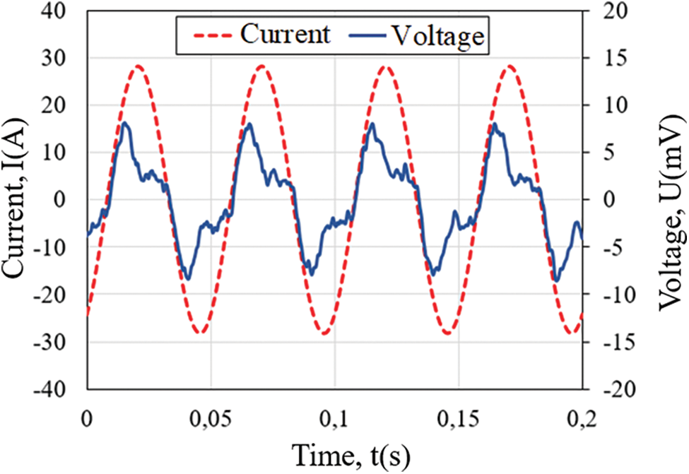
Figure 7: Measured voltage and current with compensation (Case (a), Irms = 20 A, f = 20 Hz)
The measured losses with respect to the RMS value of the current, in self-field condition, are given in Fig. 8, obtained by using both the synchronous detection and the oscilloscope. Both methods give the same losses in this case. As expected, the losses increase with the current, in a nonlinear way, and increase with the frequency. The measured losses with respect to the RMS value of the current, in the proximity of a ferromagnetic plate (Case (b)), are given in Fig. 9. Only the total losses (AC losses in the HTS + Iron losses in the ferromagnetic plate) can be directly measured using the four-point method described in Fig. 1. In order to separate the AC losses in the HTS from the iron losses in the ferromagnetic plate, a copper made coil of the same structure as the HTS coil has been used [17,18]. The results in Fig. 9 highlight the effect of the proximity of the ferromagnetic plate on the AC losses in the HTS which have significantly increased compared to that obtained in the self-field condition (Case (a)).
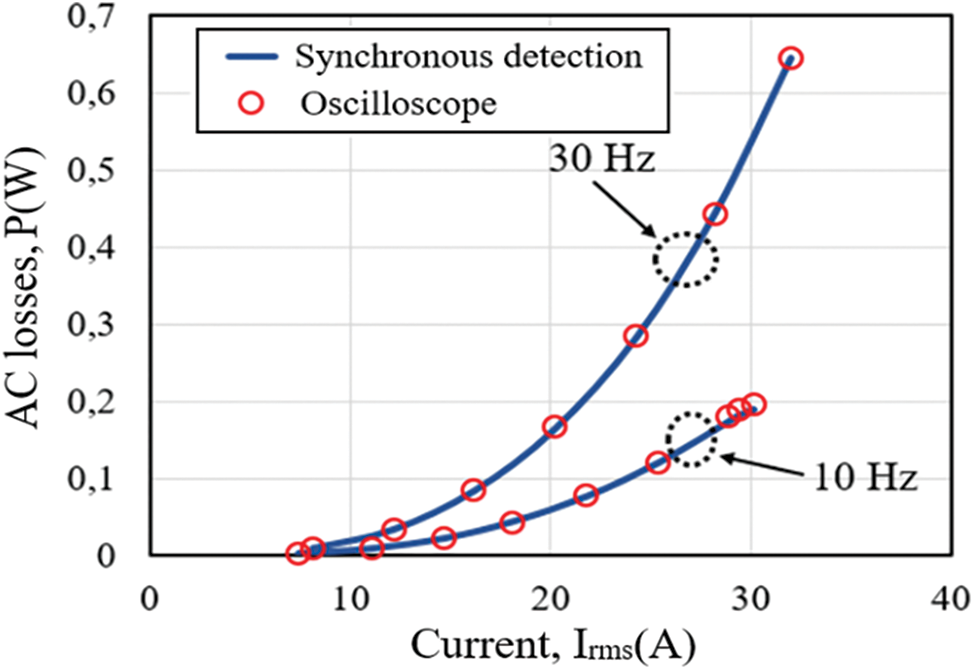
Figure 8: Measured losses using the synchronous detection and the oscilloscope in the Case (a), for two frequencies
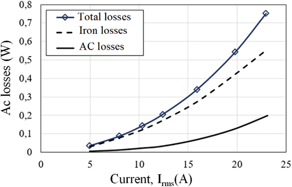
Figure 9: Measured AC losses in the proximity of the ferromagnetic plate (Case (b))
This work constitutes a contribution to the experimental characterization of HTS for the improvement of their integration in electric power systems, in particular in electrical machines. Configurations reproducing the electromagnetic environment of superconducting coils in an electric machine have been studied, highlighting the influence of the proximity of magnetically active materials on the critical current and the AC losses. Some experimental issues and their solutions have also been addressed. Moreover, the provided experimental results can be used for the validation of future calculation models.
As future work, the characterization will be extended to a rotating magnetic field, in multiphase configuration, to better approach the electromagnetic environment of an electric machine.
Funding Statement: The authors received no specific funding for this study.
Conflicts of Interest: The authors declare that they have no conflicts of interest to report regarding the present study.
1. Tixador, P. (1995). Les Supraconducteurs. Hermés, Science Publications, Paris. [Google Scholar]
2. Ainslie, M., Izumi, M., Miki, M. (2016). Recent advances in superconducting rotating machines: An introduction to the ‘Focus on superconducting rotating machines’. Superconductor Science and Technology, 29(6), 060303. DOI 10.1088/0953-2048/29/6/060303. [Google Scholar] [CrossRef]
3. Zhang, M., Eastham, F., Yuan, W. (2016). Design and modeling of 2G HTS armature winding for electric aircraft propulsion applications. IEEE Transactions on Applied Superconductivity, 26(3), 1–5. DOI 10.1109/TASC.2016.2536798. [Google Scholar] [CrossRef]
4. Dezhin, D., Ivanov, N., Kovalev, K., Kobzeva, I., Semenihin, V. (2017). System approach of usability of HTS electrical machines in future electric aircraft. IEEE Transactions on Applied Superconductivity, 28(4), 1–5. DOI 10.1109/TASC.2017.2787180. [Google Scholar] [CrossRef]
5. Bendali, S. (2012). Dimensionnement d’un moteur supraconducteur HTc. (Ph.D. Thesis). Lorraine University, France. [Google Scholar]
6. Dorget, R., Nouailhetas, Q., Colle, A., Berger, K., Sudo, K. et al. (2021). Review on the use of superconducting bulks for magnetic screening in electrical machines for aircraft applications. Materials, 14, 2847. DOI 10.3390/ma14112847. [Google Scholar] [CrossRef]
7. Manolopoulos, C., Iacchetti, M., Smith, A., Berger, K., Husband, M. et al. (2018). Stator design and performance of superconducting motors for aerospace electric propulsion systems. IEEE Transactions on Applied Superconductivity, 28(4), 5207005. DOI 10.1109/TASC.2018.2814742. [Google Scholar] [CrossRef]
8. Statra, Y., Menana, H., Douine, B. (2020). 3D Semi-analytical modeling and optimization of fully HTS ironless axial flux electrical machines. Physica C: Superconductivity and its Applications, 574, 1353660. DOI 10.1016/j.physc.2020.1353660. [Google Scholar] [CrossRef]
9. Gianni, L., Bindi, M., Fontana, F., Ginocchio, S., Martini, L. et al. (2006). Transport AC losses in YBCO coated conductors. IEEE Transactions on Applied Superconductivity, 16(2), 147–149. DOI 10.1109/TASC.2006.870819. [Google Scholar] [CrossRef]
10. Campbell, A. M. (1982). A general treatment of losses in multifilamentary superconductors. Cryogenics, 22(1), 3–16. DOI 10.1016/0011-2275(82)90015-7. [Google Scholar] [CrossRef]
11. Norris, W. T. (1970). Calculation of hysteresis losses in hard superconductors carrying ac: Isolated conductors and edges of thin sheets. Journal of Physics D: Applied Physics, 3(4), 489–507. DOI 10.1088/0022-3727/3/4/308. [Google Scholar] [CrossRef]
12. Douine, B., Lévêque, J., Rezzoug, A. (2000). AC loss measurements of a high critical temperature superconductor transporting sinusoidal or non-sinusoidal current. IEEE Transactions on Applied Superconductivity, 10(1), 1489–1492. DOI 10.1109/TASC.2018.2882059. [Google Scholar] [CrossRef]
13. Statra, Y., Menana, H., Douine, B. (2020). Contribution to the experimental characterization of the electromagnetic properties of HTS. Progress in Electromagnetics Research M, 93, 137–144. DOI 10.2528/PIERM20050705. [Google Scholar] [CrossRef]
14. Kim, Y. B., Hempstead, C. F., Strnad, A. R. (1962). Critical persistent currents in hard superconductors. Physical Review Letters, 9(7), 306–309. DOI 10.1103/PhysRevLett.9.306. [Google Scholar] [CrossRef]
15. Okamoto, H., Kiss, T., Nishimura, S., Inoue, M., Kanazawa, M. et al. (2001). Angular dependence of the extended E–J characteristics in Bi-2223/Ag sheathed tape. Physica C: Superconductivity, 357, 1190–1192. DOI 10.1016/S0921-4534(01)00479-8. [Google Scholar] [CrossRef]
16. Sumitomo Electric (2021). https://sumitomoelectric.com. [Google Scholar]
17. Li, Y., Jiang, Z., Sidorov, G., Koraua, R., Sogabe, Y. et al. (2019). AC loss measurement in HTS coil windings coupled with iron core. IEEE Transactions on Applied Superconductivity, 29(5), 4701805. DOI 10.1109/TASC.2019.2901963. [Google Scholar] [CrossRef]
18. Fukui, S., Ogawa, J., Takahashi, J., Kobu, Y., Sato, T. et al. (2019). Study on AC loss characteristics of 3-phase HTS coils with iron core and its reduction. IEEE Transactions on Applied Superconductivity, 29(5), 8201305. DOI 10.1109/TASC.2019.2902692. [Google Scholar] [CrossRef]
 | This work is licensed under a Creative Commons Attribution 4.0 International License, which permits unrestricted use, distribution, and reproduction in any medium, provided the original work is properly cited. |