| Fluid Dynamics & Materials Processing |
DOI: 10.32604/fdmp.2022.021839
ARTICLE
Thermal Analysis of Melting Occurring Inside a Finned Rectangular Enclosure Equipped with Discrete Pulsed Protruding Heat Sources
1Faculty of Sciences, Department of Physics, Laboratory of Innovation in Sciences Technology and Modeling, Chouaib Doukkali University, El Jadida, Morocco
2Faculty of Sciences Semlalia, Fluid Mechanics and Energetic Laboratory, Department of Physics, Cadi Ayyad University, Marrakesh, Morocco
*Corresponding Author: Hamid El Qarnia. Email: elqarnia@uca.ac.ma
Received: 08 February 2022; Accepted: 01 March 2022
Abstract: This paper numerically investigates the effect of the location of a horizontal fin on the melting of a phase change material (PCM) inside a rectangular enclosure heated by multiple discrete pulsed protruding heat sources. The fin and the phase change material filling the enclosure store the thermal energy extracted from the heat sources, in sensible and latent forms. The heat sources are assumed to simulate electronic components undergoing a superheating technical issue. By extracting heat from the electronics, the PCM plays the role of a heat sink. To analyze the thermal behavior and predict the cooling performance of the proposed cooling system, we derive a nonlinear mathematical model based on mass, momentum and energy conservation laws. Several numerical investigations are conducted to quantify the influence of the fin position on the thermal behavior and the cooling performance of the heat sink. Predictions include the transient maximum temperature occurring inside the heat sources and the liquid volume. A comparison between our numerical results and experimental data selected from the literature shows a good agreement. The main conclusion is that the presence of the fin leads to a slight increase in the melting time.
Keywords: Phase change material; melting; heat transfer; pulsed heating; electronics cooling; heat storage; fin
Nomenclature
| A | Aspect ratio = length/width = l/w |
| a | Amplitude of the generated power (W/m) |
| b | Porosity function |
| c | Specific heat capacity (J/kg.K) |
| e | Thickness (m) |
| f | Dimensionless frequency |
| f1 | liquid fraction |
| H | Length of the fin (m) |
| h | Specific enthalpy (J/kg) |
| k | Thermal conductivity (W/m. K) |
| K | Dimensionless thermal conductivity |
| l | Height of the enclosure (m) |
| lo | Characteristic length representing the mass of the PCM (m) |
| p | Pressure (Pa) |
| pe | Period (s) |
| Pr | Prandtl number |
| Qv | Heat generation per unit length of the heat source (W/m) |
| | Mean power (W/m) |
| Ra | Rayleigh number |
| Ste | Stefan number |
| T | Temperature (K) |
| U, V | Dimensionless velocity in X and Y directions |
| w | Width of the enclosure (m) |
| X, Y | Dimensionless Cartesian coordinates |
| Greek symbols | |
| ρ | Density (kg/m3) |
| α | Thermal diffusivity (m²/s) |
| θ | Dimensionless temperature |
| ΔH | Latent heat (J/kg) |
| Γ | Dimensionless distance between two heat sources |
| η | Dimensionless coordinate normal to the wall–heat sources/liquid PCM interface |
| τ | Dimensionless time |
| Subscripts | |
| l | Liquid |
| m | Melting, PCM |
| max | maximum |
| min | minimum |
| s | Substrate, solid |
The melting of a solid-liquid phase change material (PCM) in a rectangular enclosure equipped with discrete protruding heat sources, flush-mounted on one of its vertical walls, has been the subject of several analytical, experimental and numerical investigations [1–10]. Chu et al. [1] were the first to investigate the effect of heater size, location, aspect ratio and boundary conditions for a laminar flow and arrive at a relationship between the Rayleigh number and the optimum position of the heat source that maximizes heat transfer. Zhang et al. [2] have studied the melting of n-octadecane employing a constant and uniform heat generation and found out a reduction of 50% in the heat source average temperature compared to that obtained by air-cooled natural convection (for a certain period of time). In the case a cavity with thermally insulated horizontal walls and three sources, Ju et al. [6] showed that this reduction can reach up to 70% using a PCM instead of ethylene glycol. Binet et al. [3] showed that a high aspect ratio better controls the heat sources temperature and offers relatively extended melting durations. The influence of changes in the pulses frequency, heat source location and the aspect ratio on the thermal performance of the PCM unit appear to be significant as examined by Krishnan et al. [7]. In order to mitigate the hot spots, Birinci et al. [8] have determined an optimum ratio using six different heat sources with different electrical powers, where the average and total heat generation rates are kept equal for all the examined cases. The Reynolds number varied from 792 to 3962 and all the three known heat transfer mechanisms have been taken into account with an integrated approach to calculate the dimensionless global conductance of the integrated circuit pack. Three numerical simulations have been performed using ANSYS Fluent and measurements have been collected for the surface temperature. The output parameters of the study are the surface and hot spot temperatures, Nusselt number and dimensionless global conductance change with Reynolds number and heat generation ratio. The results have revealed that the relative decrease in the heat generation rates are convenient for the hot spot mitigation.
The inclusion of fins, as an artificial additional heat exchange surface, within a rectangular enclosure filled with PCM and equipped with discrete protruding heat sources has been considered in the past, however in a few limited studies, where the investigation shave focused on of the effect of the fin dimensions, positions and numbers. Joneidi et al. [9] carried out an experimental study to assess the melting phenomenon occurring in a horizontal heat sink with plate fins by changing their height and number. With regard to their results, increasing the number of fins increases the base plate temperature, decreases the melting rate and leads to a much uniform temperature distribution, which demonstrates the correlation between these quantities and the cavity geometrical parameters. On the other hand, an increase in the fin thickness results in a reduction in the melting time [10]. Abdi et al. [11] studied the effect of vertically oriented fins on the heat transfer and energy density in an enclosure heated from the bottom. Their numerical results showed that the number and length of the fins have a significant effect on the natural convection patterns and hence on the heat transfer rates as well as on the energy storage. Using a large number of longer fins leads to the highest melting rate, while small number of shorter fins results in the lowest heat transfer rate. In addition to that, it appears that elongating the fins is significantly important than increasing their number. Joshi et al. [12] have numerically analyzed the effect of the size and location of the fin on the melting time of PCM. They have examined four different configurations and showed that the fin-to-PCM volume ratio decreases by half while the total volume of the thermal energy storage increases.
Our aim in this study is to examine the effect of a horizontal rectangular fin position on the melting process of a phase change material inside a rectangular enclosure heated by multiple pulsed protruding discrete heat sources. As mentioned earlier, the inclusion of fins inside cavities has not received enough attention even though it is of interest to engineering and applied applications. In the next section, we formulate a two-dimensional model capable of describing heat transfer features of the proposed finned rectangular enclosure during the melting process of a PCM. The melting process is initiated by heat extracted from three pulsed protruding heat sources mounted on the left wall of the enclosure. In order to describe the fluid flow with natural convection, mass, momentum and energy conservation equations are derived, appropriately normalized, numerically solved using the finite volume method and finally validated against experimental data selected from the literature.
The system under consideration, shown in Fig. 1, consists of a phase change material (PCM), n-eicosane, filling a rectangular enclosure of height l and width w attached to a substrate of thickness e. Three identical pulsed protruding heat sources (simulating electronic components), each of height lc and thickness ec, are flush-mounted on the left wall. The distance between two consecutive heat sources is Γ, and the distance between the bottom enclosure wall and the lower heat source is δ. The length and thickness of the horizontal fin are H and ef, respectively. The thermal conductivity, kc, the specific heat capacity at constant pressure, cp,c, and mass density, ρc of the heat sources are different from those of the wall (substrate), ks, cp,s and ρs. The enclosure can be used either as a latent heat storage unit to store thermal energyorasa heat sink to cool electronic devices such as the heat sources, the conductive walls and the substrate. The pulsed power generated within the heat sources per unit length, denoted by Qv, is displayed in Fig. 2 and thus
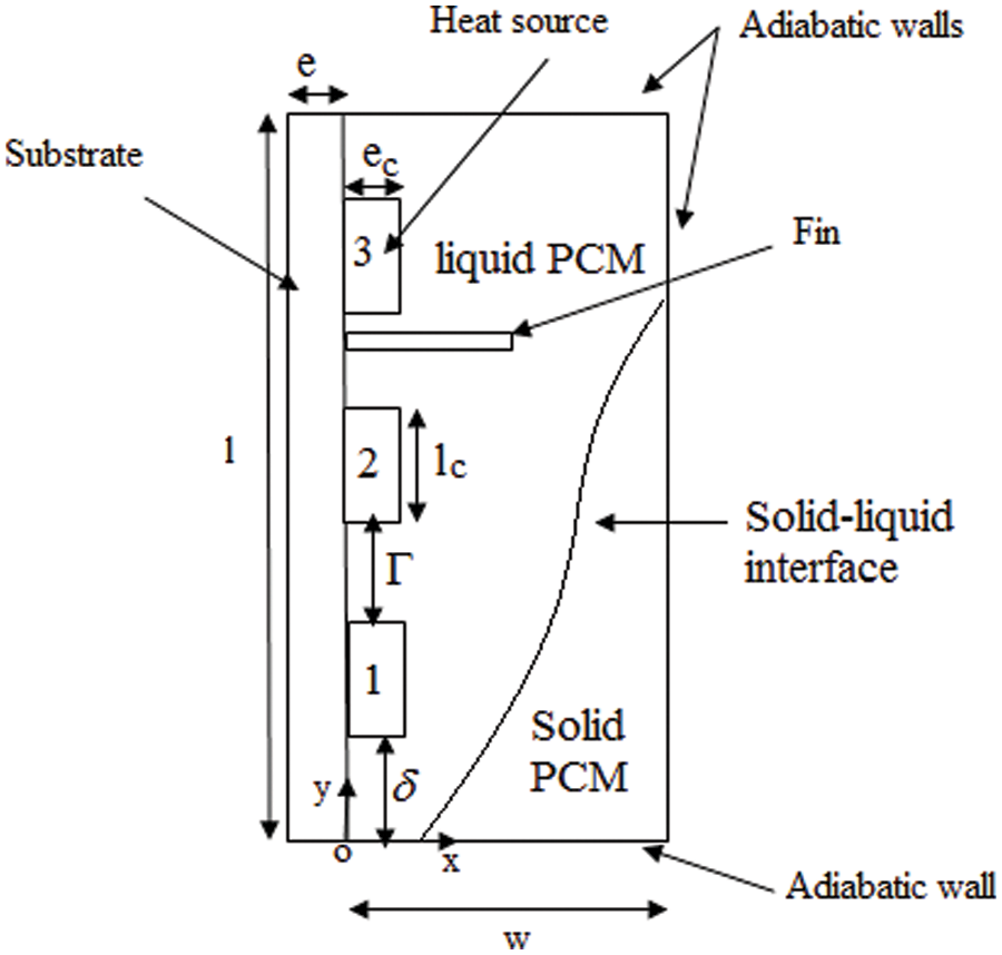
Figure 1: The schematic view of the rectangular enclosure
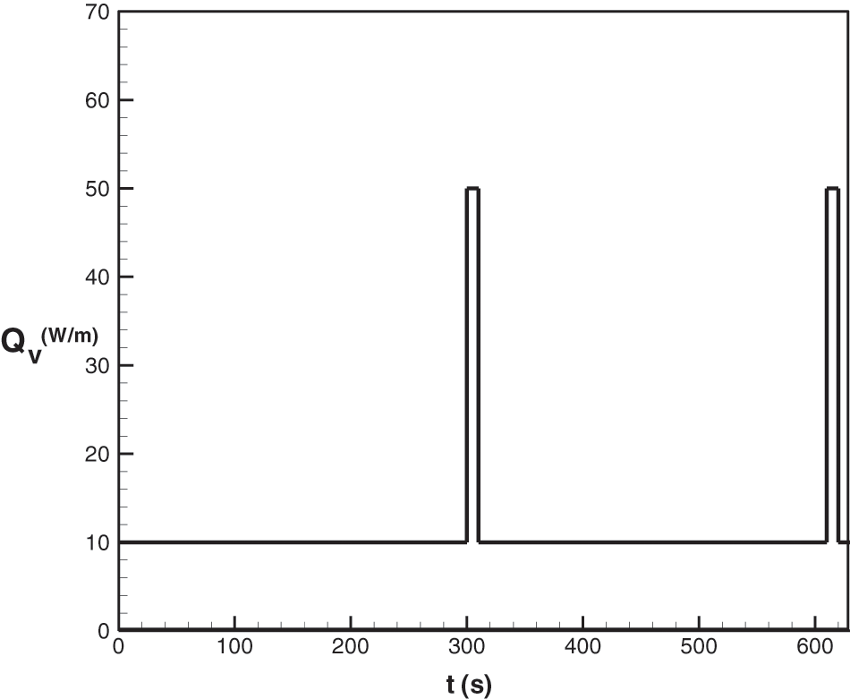
Figure 2: Pulsed power generated by the heat sources during the first two cycles
In all solid media (solid PCM, left wall, heat sources and fin), the heat transfer occurs by pure conduction, while in the liquid PCM it is ensured by advection. We track the moving solid-liquid interface that separates the solid and liquid phases of the PCM by solving the equation for the liquid volume fractionf1. The heat transfer and melting process are governed by mass, momentum and energy conservation equations where a number of assumptions have been used:
• The liquid PCM is Newtonian and incompressible;
• The flow is laminar;
• The Boussinesq approximation is adopted (assuming a linear variation of density with temperature);
• The thermophysical properties are held constant over the range of temperatures considered;
• The volume change of the PCM during melting is neglected;
• The phase change is isothermal;
• The viscous dissipation is neglected in the liquid PCM.
Under these assumptions, the independent state variables necessary for an adequate description of such a physical problem are the x and y components of the transient velocity field u(x, y, t) and v(x, y, t) and the field of temperature T(x, y, t). We have appropriately scaled the governing equations using the following dimension less space and time, physical parameters and the independent state variables:
where
Mass conservation equation
Momentum equations
Energy conservation equation
where the different source terms involved in the model are given by
Written in terms of the Heaviside function
Two constants appear in Eq. (6),
The temperature and heat flux density are continuous functions at all interfaces: wall-heat sources, wall-PCM, heat sources-PCM, fin-PCM and fin-wall. The solid surfaces are regarded as impermeable and for which the no-slip condition applies. Seeking solutions of the coupled governing partial differential equations requires the knowledge of initial and boundary conditions. The initial conditions for the system under consideration are:
The boundary conditions are given in the following way:
Adiabatic walls:
Wall-heat source interface:
Wall-PCM interface:
Wall-fin interface:
Heat sources–PCM interface:
Heat fin–PCM interface:
Wall:
Here, the quantity η refers to the coordinate normal to the heat source-PCM interface. The above governing equations are discretized using the finite volume method (FVM) in a staggered mesh, which consists of M and N nodes in X and Y directions, respectively. The power law scheme is used for the evaluation of the total flux combining both advective and conductive terms. The SIMPLE routine is used to couple pressure and velocity equations [13]. The energy equation (Eq. (5)) is solved to determine the temperature field in all parts of the enclosure (PCM, wall, heat sources and fin). Note that the source term Sϴ = 0, except in the PCM, where
In the numerical implementation, the value of liquid volume fraction fl is determined iteratively from the solution of the energy equation. A tri-diagonal matrix iterative method is used to solve the algebraic equations for U, V and θ. The iterative procedure is applied until reaching a well appropriate converging solution for the flow and energy fields at each time step, that is, when the criteria relating mass and energy balances are smaller than 10−9 and 10−3, respectively. Numerical calculations were performed to check the grid size and the time step effects on fl and ϴm. The results reveal that the grid size set to 50 × 60 and the time step to 4.509 × 10⁻⁴ ensure the best compromise between the execution time and the accuracy of the results.
The numerical predictions of the model developed in this study are compared to experimental data obtained by Casano et al. [15] who numerically and experimentally studied a one-dimensional phase-change process dominated by heat conduction. In their experimental arrangement sketched in Fig. 3, a plane slab of PCM (n-octadecane) was heated from above by a periodically heat flux density
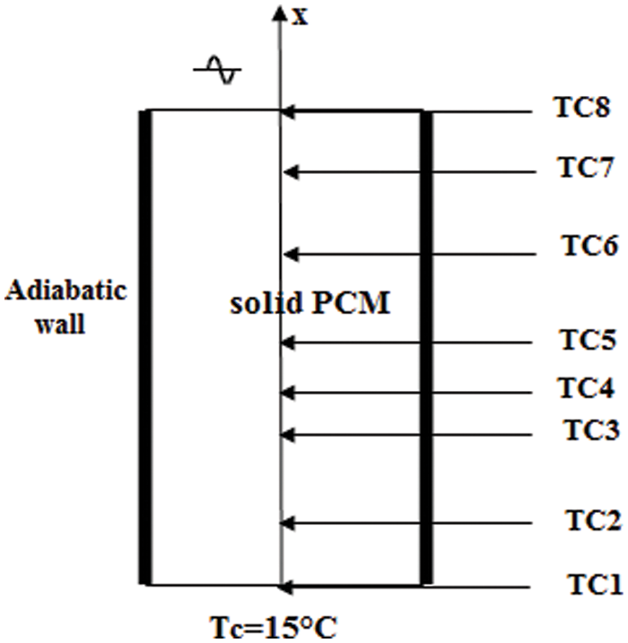
Figure 3: Schematic of the plan slab of PCM
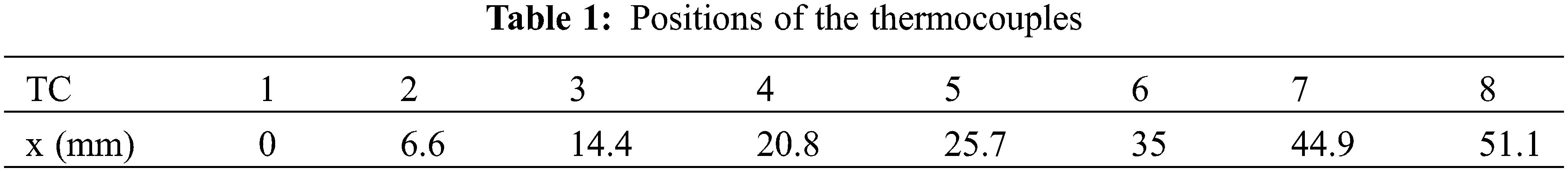
Fig. 4 displays our predicted and their measured temperatures corresponding to the eight locations in the PCM and a rather nice agreement is obtained.
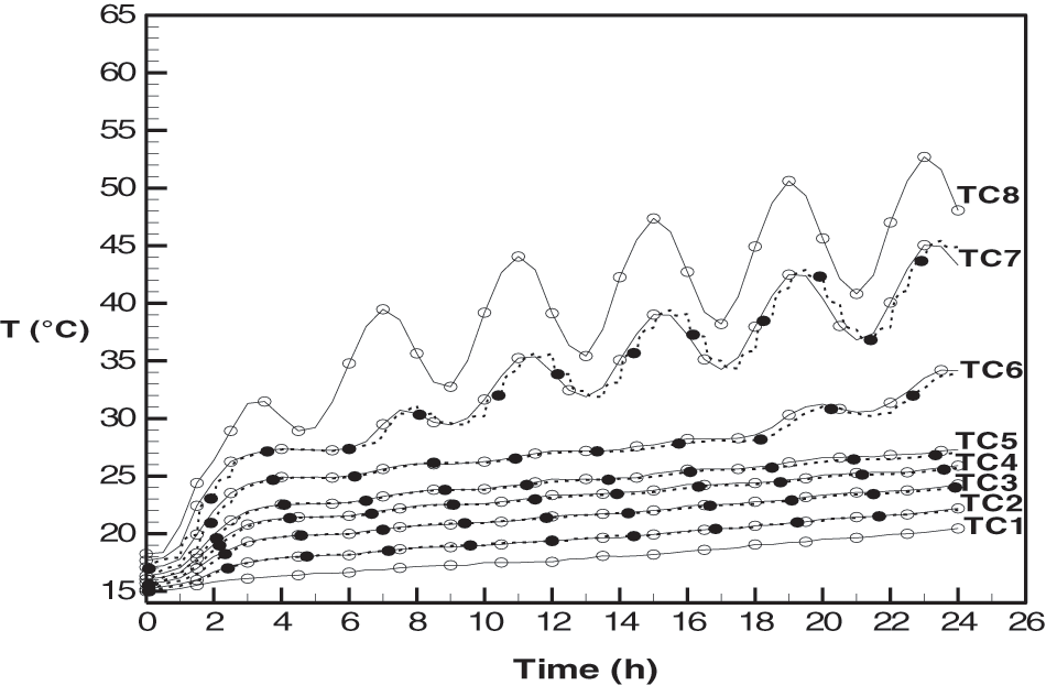
Figure 4: Comparison between computed (lines) and measured (in symbols) temperature distributions vs. time for a period of 4 h. Symbols are data from [15]
Numerical simulations are performed to highlight the effect of the fin position on the thermal behavior of the PCM enclosure. The PCM used for simulations is the n-eicosane. The geometrical parameters and the thermophysical properties of the components of the physical model are listed in Tables 2 and 3. The dimensionless frequency of the pulsed power generated in each heat source is f = 35.76 (period Pe = 310 s). We have carried out our simulations for five cases one without a fin and the remaining four cases correspond to four different positions for a fin position:
• P1: below the lower heat source.
• P2: between the lower and the central heat sources.
• P3: between the central and the upper heat sources.
• P4: above the upper heat source.
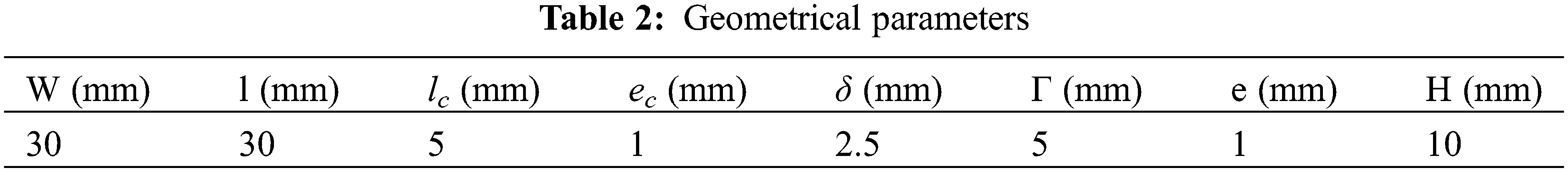
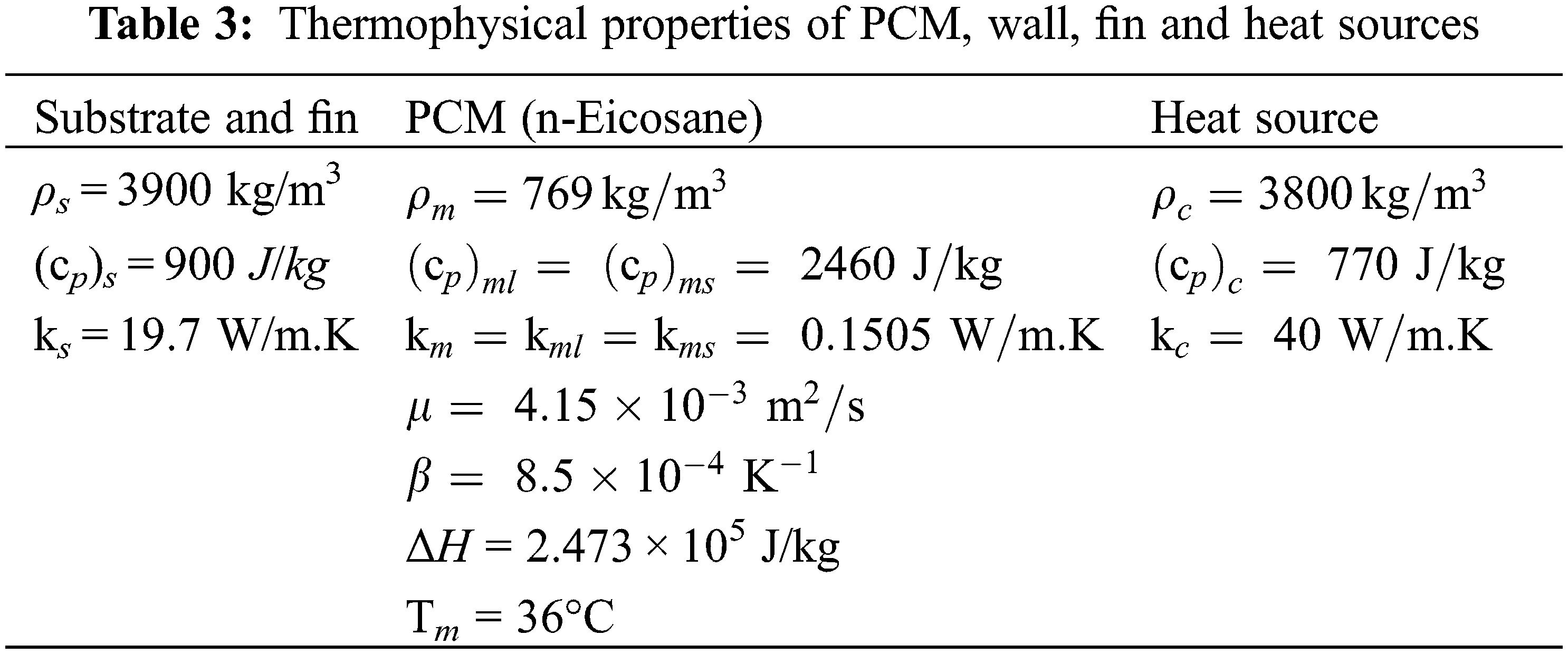
Fig. 5 displays the dimensionless maximum temperature of the heat sources against the normalized time for four fin positions. The temperature oscillates due to the periodic nature of the power generated in the heat sources and its maximum is reduced by the presence of the fin. During the first six cycles, the largest maximum temperature is the one that is associated with the PCM enclosure without a fin. The numerical analysis also shows that the time evolution of the maximum temperature is characterized by three different regimes. The first regime corresponds to the first two periods and is characterized by an increase in both the minima and maxima of the maximum temperature for all the examined cases of the fin positions. During this regime, which also corresponds to the inception of the melting process, the heat transfer occurring in the liquid PCM layer is mainly dominated by conduction. The second regime starts when the liquid PCM zone largely expands and the natural convection movement takes place within the melt state. The growth of the liquid layer with time intensifies the natural convection and results in an improvement of the heat transfer extracted from the heat sources. Note that during this regime, the difference between the minima associated with the different fin positions decreases from one cycle to another. The same is also detected in the maxima of the maximum temperature. The analysis of the figure also shows that the quasi-steady state is reached after five cycles. As the time progresses, the PCM continues to melt and stores thermal energy essentially as a latent heat. The liquid layer expands and the liquid volume fraction increases with time as illustrated in Fig. 6. After ten cycles (τ = 0.34), the liquid volume fraction reaches 70% of the total PCM volume, and the melt stores thermal energy, not only in a latent form but also in a sensible one. This results in an increase in the average temperature of the liquid PCM and hence in a reduction in the temperature difference between the liquid PCM and the heat emanating from different surfaces (heat sources and substrate surfaces). Therefore, the extracted heat transfer from heat sources drops and this leads to an augmentation in both the maxima and minima of the maximum temperature of the heat sources.
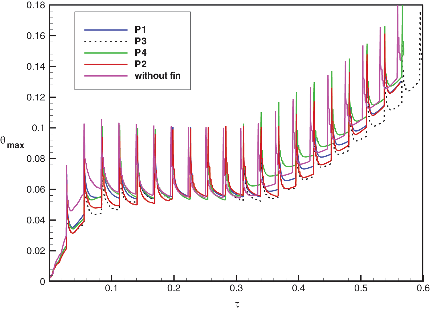
Figure 5: Effect of fin position on the temporal variation of the dimensionless maximum temperature
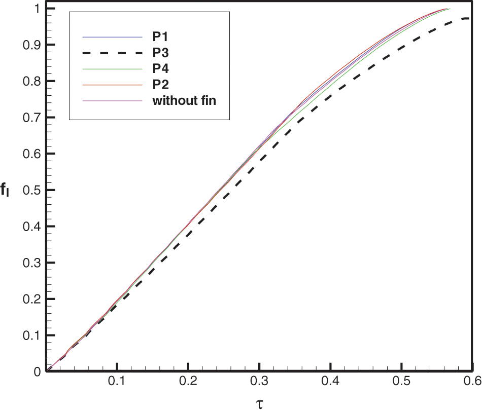
Figure 6: Effect of the fin position on the temporal variation of the liquid fraction
Among all the fin positions considered in this study, the position of the fin placed between the central and the upper heat sources (P3) corresponds to the lowest values for both the minima and maxima of the maximum temperature generated by the heat sources that have the ability to evacuate more heat compared to the other position cases. In addition, such a position results in the slowest melting process corresponding tothe relatively smallest melting time. These findings might be of great importance for electronics cooling applications. Moreover, Fig. 6 demonstrates that the melting time of the PCM is almost the same for the three already defined positions P1, P2 and P4 and for the case of an enclosure without a fin.
We have investigated, through a modelling effort, numerical analysis and validation, the effect of the fin position on the thermal behavior and the cooling performance of a heat sink consisting of a PCM (n-eicosane) filling a rectangular enclosure equipped with three-pulsed discrete heat sources. The presence of a fin appears to be favorable for cooling electronic modules. The main outcomes of this study areas as follows:
• The time evolution of the dimensionless maximum temperature of the heat sources exhibits three distinct regimes;
• The lowest value of the maximum temperature and the largest melting time are obtained for a fin located between the central and the upper heat sources, while the opposite is obtained in the case of an enclosure without a fin.
Funding Statement: The authors received no specific funding for this study.
Conflicts of Interest: The authors declare that they have no conflicts of interest to report regarding the present study.
1. Chu, H. H. S., Churchill, S. W., Patterson, C. V. S. (1976). The effect of heater size, location, aspect ratio, and boundary conditions on two-dimensional, laminar, natural convection in rectangular channels. Journal of Heat Transfer, 98, 195–201. DOI 10.1115/1.3450518. [Google Scholar] [CrossRef]
2. Zhang, Y., Chen, Z., Wang, Q., Wu, Q. (1993). Melting in an enclosure with discrete heating at a constant rate. Experimental Thermal and Fluid Science, 6, 196–201. DOI 10.1016/0894-1777(93)90029-I. [Google Scholar] [CrossRef]
3. Binet, B., Lacroix, M. (2000). Melting from heat sources flush mounted on A conducting vertical wall. International Journal of Numerical Methods in Heat Fluid Flow, 10, 286–303. DOI 10.1108/09615530010318017. [Google Scholar] [CrossRef]
4. Zhang, Y., Chen, Z., Wang, Q., Wu, Q. (1994). Analysis of melting in an enclosure with discrete heating at a constant rate. International Journal of Numerical Methods in Heat Fluid Flow, 15, 79–82. DOI 10.1016/0142-727X(94)90034-5. [Google Scholar] [CrossRef]
5. Desrayaud, G., Fichera, A., Lauriat, G. (2007). Natural convection air-cooling of a substrate-mounted protruding heat source in a stack of parallel boards. International Journal of Numerical Methods in Heat Fluid Flow, 28, 469–482. DOI 10.1016/j.ijheatfluidflow.2006.07.003. [Google Scholar] [CrossRef]
6. Ju, Y., Zhou, Y., Chen, Z. (1998). Experimental study of melting heat transfer in an enclosure with three discrete protruding heat sources. Experimental Heat Transfer, 11, 171–186. DOI 10.1080/08916159808946560. [Google Scholar] [CrossRef]
7. Krishnan, S. H., Garimella, V. (2004). Analysis of a phase change energy storage system for pulsed power dissipation. IEEE Transactions on Components and Packaging Technologies, 27, 191–199. DOI 10.1109/TCAPT.2004.825758. [Google Scholar] [CrossRef]
8. Birinci, S., Saglam, M., Sarper, B., Aydin, O. (2020). Constructal design of heat sources with different heat generation rates for the hot spot mitigation. International Journal of Heat and Mass Transfer, 163, 120472. DOI 10.1016/j.ijheatmasstransfer.2020.120472. [Google Scholar] [CrossRef]
9. Joneidi, M. H., Rahimi, M. R., Pakrouh, B. (2020). Experimental analysis of transient melting process in a horizontal cavity with different configurations of fins. Renewable Energy, 145, 2451–2462. DOI 10.1016/j.renene.2019.07.114. [Google Scholar] [CrossRef]
10. Acır, A., Canlı, M. E. (2018). Investigation of fin application effects on melting time in a latent thermal energy storage system with phase change material (PCM). Applied Thermal Engineering, 144, 1071–1080. DOI 10.1016/j.applthermaleng.2018.09.013. [Google Scholar] [CrossRef]
11. Abdi, A., Martin, V., Chiu, J. N. W. (2019). Numerical investigation of melting in a cavity with vertically oriented fins. Applied Energy, 235, 1027–1040. DOI 10.1016/j.apenergy.2018.11.025. [Google Scholar] [CrossRef]
12. Joshi, V., Rathod, M. K. (2019). Constructal enhancement of thermal transport in latent heatstorage systems assisted with fins. International Journal of Thermal Sciences, 145, 105984. DOI 10.1016/j.ijthermalsci.2019.105984. [Google Scholar] [CrossRef]
13. Patankar, S. V. (1983). Numerical heat transfer and fluid flow. Hemisphere: Washington. [Google Scholar]
14. Voller, V. R. (1997). An overview of numerical methods for solving phase change problems. Advances in Numerical Heat Transfer, vol. 1. [Google Scholar]
15. Casano, G., Piva, S. (2002). Experimental and numerical investigation of the steady periodic solid-liquid phase-change heat transfer. International Journal of Heat and Mass Transfer, 45, 4181–4190. DOI 10.1016/S0017-9310(02)00122-9. [Google Scholar] [CrossRef]
 | This work is licensed under a Creative Commons Attribution 4.0 International License, which permits unrestricted use, distribution, and reproduction in any medium, provided the original work is properly cited. |