| Fluid Dynamics & Materials Processing |
DOI: 10.32604/fdmp.2022.021925
ARTICLE
Application of an Artificial Neural Network Method for the Prediction of the Tube-Side Fouling Resistance in a Shell-And-Tube Heat Exchanger
1Research Laboratory “Process, Energy, Environment & Electrical Systems”, National Engineering School of Gabes, Gabes, 6029, Tunisia
2CMGPCE Laboratory, French Institute of Refrigeration (IFFI), National Conservatory of Arts and Crafts (CNAM), Paris, 75141, France
*Corresponding Author: Rania Jradi. Email: raniajradi@yahoo.fr
Received: 13 February 2022; Accepted: 09 March 2022
Abstract: The accumulation of undesirable deposits on the heat exchange surface represents a critical issue in industrial heat exchangers. Taking experimental measurements of the fouling is relatively difficult and, often, this method does not lead to precise results. To overcome these problems, in the present study, a new approach based on an Artificial Neural Network (ANN) is used to predict the fouling resistance as a function of specific measurable variables in the phosphoric acid concentration process. These include: the phosphoric acid inlet and outlet temperatures, the steam temperature, the phosphoric acid density, the phosphoric acid volume flow rate circulating in the loop. Some statistical accuracy indices are employed simultaneously to justify the interrelation between these independent variables and the fouling resistance and to select the best training algorithm allowing the determination of the optimal number of hidden neurons. In particular, the BFGS quasi-Newton back-propagation approach is found to be the most performing of the considered training algorithms. Furthermore, the best topology ANN for the shell and tube heat exchanger is obtained with a network consisting of one hidden layer with 13 neurons using a tangent sigmoid transfer function for the hidden and output layers. This model predicts the experimental values of the fouling resistance with AARD% = 0.065, MSE = 2.168 × 10⁻¹¹, RMSE = 4.656 × 10⁻⁶ and r2 = 0.994.
Keywords: Artificial neural network; fouling resistance; phosphoric acid concentration process; shell-and-tube heat exchanger
Nomenclature
| A | Heat transfer area |
| C | Corrective factor |
| Cp | Specific heat |
| F | Fouling resistance |
| g | Gravity acceleration |
| HMT | Total head of the pump |
| | Mass flow rate |
| P | Pressure |
| Q | Heat transfer rate |
| T | Temperature |
| t | Time |
| U | Overall heat transfer coefficient |
| | Volume flow rate |
| Greek Letter | |
| ρ | Density |
| Indices and Exhibitors | |
| ac | Acid |
| c | Clean state |
| cir | Circulation |
| d | Discharge |
| exp | Experimental |
| f | Under fouling condition |
| in | Inlet |
| ml | Logarithmic mean |
| out | Outlet |
| pred | Predicted |
| s | Sunction |
| st | Steam |
| Symbols | |
| Δ | Difference |
| || || | Average |
In the last few years, manufactures are concentrated in seek high energy performance in front of the increment in the energy prices and rarefaction of primary energy sources. In this context, manufacturers developed optimized processes and optimal technical equipment. The heat exchanger is considered as an omnipresent and essential part of the energy performance strategy. Its principle of operation is to transfer thermal energy from one fluid to another without mixing them [1]. To improve the efficiency of heat transfer and optimize the energy recovery to ensure the best profitability of this equipment can be done by various techniques, such as: optimal design, appropriate control of functioning conditions, regular cleaning and predictive maintenance of heat exchangers. One of the preponderant problems in the reduction of the performances of these installations is the fouling which created by the accumulation of solid materials on the side surfaces of heat exchangers [2]. Among several industries that are the most concerned by the fouling problem is the chemistry industries [1]. The geometry of the heat transfer surface, the operation conditions of the fluid and the heat exchanger are some variables that can have a huge effect on the fouling [3,4]. To establish an empirical or semi-empirical correlation to accurately predict exactly the fouling resistance is hard by considering all measurable variables of the system.
In the recent years, the Artificial Neural Network (ANN) approach attracted the attention through their promising results in the modeling of the complex systems, especially to estimate the fouling resistance in heat exchangers. It has been widely used, particularly in the conception and the control [1,5,6], and in the simulation of the performances [7]. This approach was also used as an alternative technique to assess the fouling resistance in tube heat exchangers [8,9]. Davoudi et al. [8] used artificial neural network (ANN) to predict the fouling factor from certain easily measurable variables of the system. The authors developed an ANN model by using an important experimental datasets for the fouling factor. Certain statistical accuracy indices and the calculation effort were employed in this research to determine the best performance algorithm and the optimal numbers of hidden neurons. They concluded that the regulation approach by back-propagation has the best performance among the considered training algorithms. In other research [9], the ANN was also utilized to build the fouling resistance model in shell and tube heat exchanger by [9]. The developed model will be used as the prediction tool in order to optimize operation conditions and predictive maintenance of shell and tube heat exchanger.
So, the purpose of this study is to develop a reliable model allowing estimating the fouling resistance with an acceptable accuracy by using 295 experimental datasets for shell and tube heat exchanger of the concentration phosphoric acid plant. The ANN method used in this work allows obtaining interesting results concerning the modeling and the prediction of the heat exchanger performances losses due to the fouling phenomena.
The role of the experimental process installed at phosphoric acid production industry is to concentrate the phosphoric acid from 28% to 54% P2O5 in a closed loop forced-circulation evaporator, operating in vacuum tanks to a barometric condenser. The flow diagram of the experimental process is shown in Fig. 1. The concentration system consists of a shell and tube heat exchanger, a centrifugal pump, a boiler or expansion chamber, a barometric condenser and a basket filter [10].
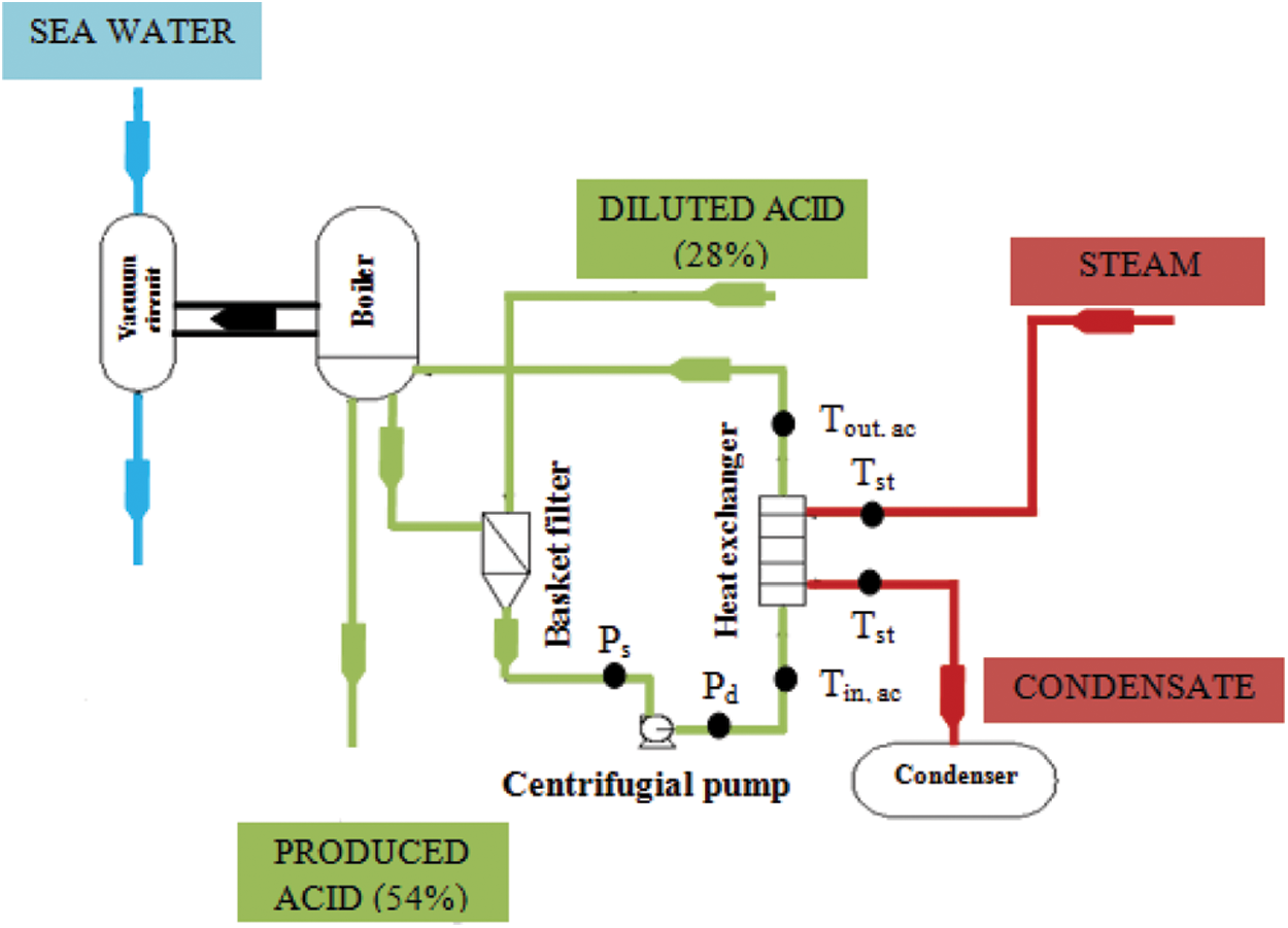
Figure 1: Schematic drawing of the experimental process
In the aim of protect the pump from abrasion and limit the fouling in the heat exchanger, the dilute and the circulating phosphoric acid mixed at the level of the basket filter. This can minimize the frequency of washing. The blend formed is then aspirated from the circulation pump which sends it to the heat exchanger in order to raise their temperature from 70°C to 80°C. In the other side of the heat exchanger, the steam undergoes a condensation at a temperature of 120°C. The condensate outlet is transmitted to a storage tank before being sent back to the utility station. In the exit level of the heat exchanger, the superheated mixture of phosphoric acid passes into the boiler where an amount of water evaporates and the concentrated acid is produced by overflowing in a piping system inside the boiler. The remaining quantity of phosphoric acid is recycled. The condenser also ensures incurring non-condensable gases coming out from the boiler by the effect of a hydro-ejector. At the bottom of the barometric guard, the sea water is recovered in a tank of guard before being released into the sea.
The experimental process is equipped with temperature and pressure sensors in order to measure and monitor the operation of the process, control pump speed, and temperatures in phosphoric acid side in heat exchanger, and therefore vary the heat transferred between the phosphoric acid and steam.
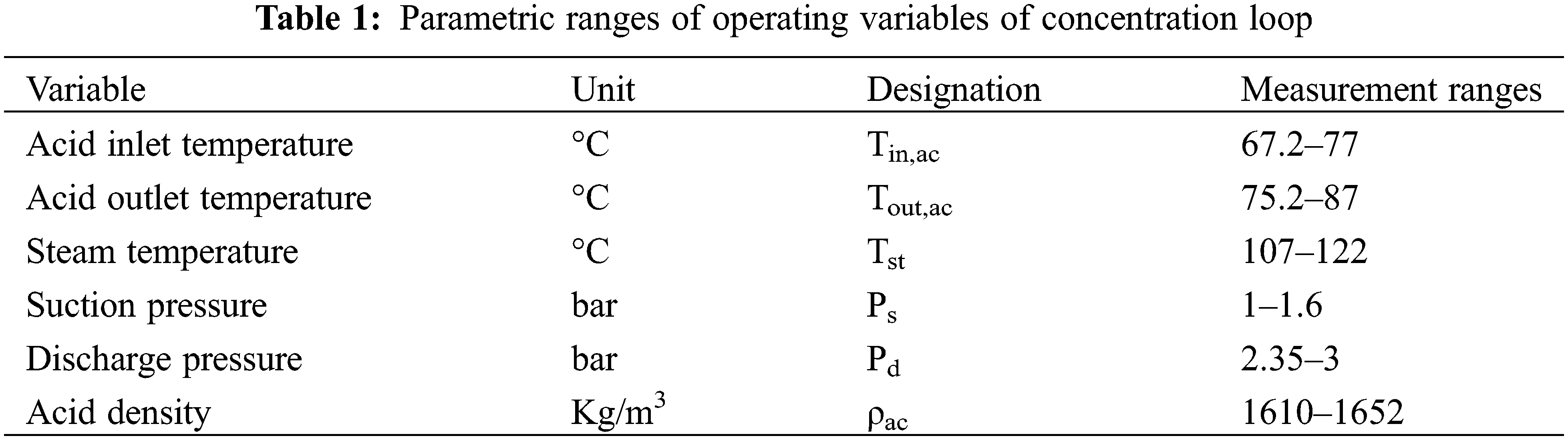
As shown in Fig. 1, the measure of temperatures and pressures were done at the input and output of the heat exchanger and the centrifugal pump, respectively. The setup was equipped with a data acquisition system. The frequency of data acquisition was every two hours due to the long time of formation of fouling deposit. A Pt100 temperature sensor was used in this study to measure the temperatures in the heat exchanger. A densimeter DMA35 and a diaphragm pressure gauge with an uncertainly of ± 0.05% and ± 1.6%, respectively, were used to measure the density of the phosphoric acid and the pressure. Table 1 presents the parametric ranges of operating variables of the concentration loop.
The aim of this section is to calculate the experimental values of fouling resistance. It can be determined by following these steps:
1. Determine the mass flow rate of circulating phosphoric acid (
The volume flow rate of circulating phosphoric acid is calculated by considering simultaneously the characteristic curve of the pump and the expression which allows calculate the total head of the pump (HMT) [1,11].
Ps and Pd are the suction and discharge pressure of the pump, respectively, ρac is the density of phosphoric acid and g is the gravity acceleration (= 9.81 m.s−2).
2. Determine the heat transfer rate which is calculated by using the following expression [1]:
Q,
3. Determine the overall heat transfer coefficients in the clean state (Uc) and under fouling condition (Uf ) [1,11]:
A is the heat transfer area, C is the corrective factor for the average logarithmic temperature difference (= 1 pure Counter Flow Arrangement) and ΔTml is the logarithmic mean temperature difference, defined as [1,11]:
It is supposed that the cleaning between operational runs is perfect and that the heat exchanger is totally free of fouling at the beginning of a new run. The overall heat transfer coefficient at the beginning of every cycle is considered as the overall heat transfer coefficient in the clean state.
4. Determine the fouling resistance (F(t)) which is given by [1]:
4 Prediction of Fouling Resistance Using Artificial Neural Network
ANN is a digital approach derived from the biological neuronal network of the human brain. It is used to learn and to recognize complex nonlinear functions. The main advantage of ANN is their learning capacity which makes a more powerful in comparison to the parametric approaches. The application of ANN in heat transfer field is popular because of its functional approximation between desired inputs and outputs [12]. This approach is used in this work as an efficient and powerful non-linear computational paradigm to model the fouling resistance. The architecture of ANN is based on placing neurons in some successive and interconnected layers. The feed-forward process is the most patterns used for connecting the layer of neurons to each other. The output (O) is calculated according to the following mathematical relationship [1]:
(wrIr) represents the weighting factor attached to the input, (b) is the bias coefficient and (T) refers to a transfer function.
The network was trained with back-propagation method in the aim of reducing the error between experimental and predicted values of fouling resistance. Tangent sigmoid transfer function was selected to be used in this study for the hidden and output layers and is expression as follows [1]:
From the experimental data already collected and the correlations used to calculate the fouling resistance, it can be concluded that the fouling depends on the following factors: - the inlet and outlet temperatures of phosphoric acid, - the steam temperature, - the density of phosphoric acid, - the volume flow rate of phosphoric acid, - and the time.
The application of ANN approach requires a big experimental data in order to link fouling resistance to its associated independent variables. In this context, 295 experimental databases on the fouling resistance in phosphoric acid concentration plant for shell-and-tube heat exchanger are collected. The range of these experimental dataset is given in Table 1.
To estimate the fouling resistance (F) in heat exchanger, the developed Multilayer Perceptron (MLP) network is composed by three layers: the input layer represents the values of the independent variables and the output layer responsible to supply the value of dependent variable, i.e., fouling resistance. A random subdivision was done in the input matrix: 70% is attributed to the training subset, 15% for the validation subset and 15% for the test subset.
4.2 Selecting the Topology of the ANN Model
To find the optimal number of hidden layers and to determine the best number of neurons in every hidden layer, it is necessary to develop a systematic procedure in order to select an appropriate design of ANN model. A MLP network composed by a single hidden layer [1,8] is able to estimate the fouling resistance in single-tube heat exchanger. On the other side, by maximization some statistical accuracy indices, the optimal number of neurons in the hidden layer can be determined.
The statistical indices used in this work are: the absolute average relative deviation (AARD %), the mean square errors (MSE), the root mean square errors (RMSE) and the correlation coefficient (r2). Their mathematical expression is given below [1]:
Table 2 gives the results of the accuracy analyses allowing finding the best number of hidden neurons for shell-and-tube heat exchanger. Several MLP networks are built trained tested and their quantitative accuracy was calculated as a function of the number of neurons which has been varied from one to twenty five. The selection of the optimal number of hidden neurons is often based on the smallest MLP network offering an acceptable accuracy. It must be emphasized that each topology is formed 20 times and only the best results are reported.
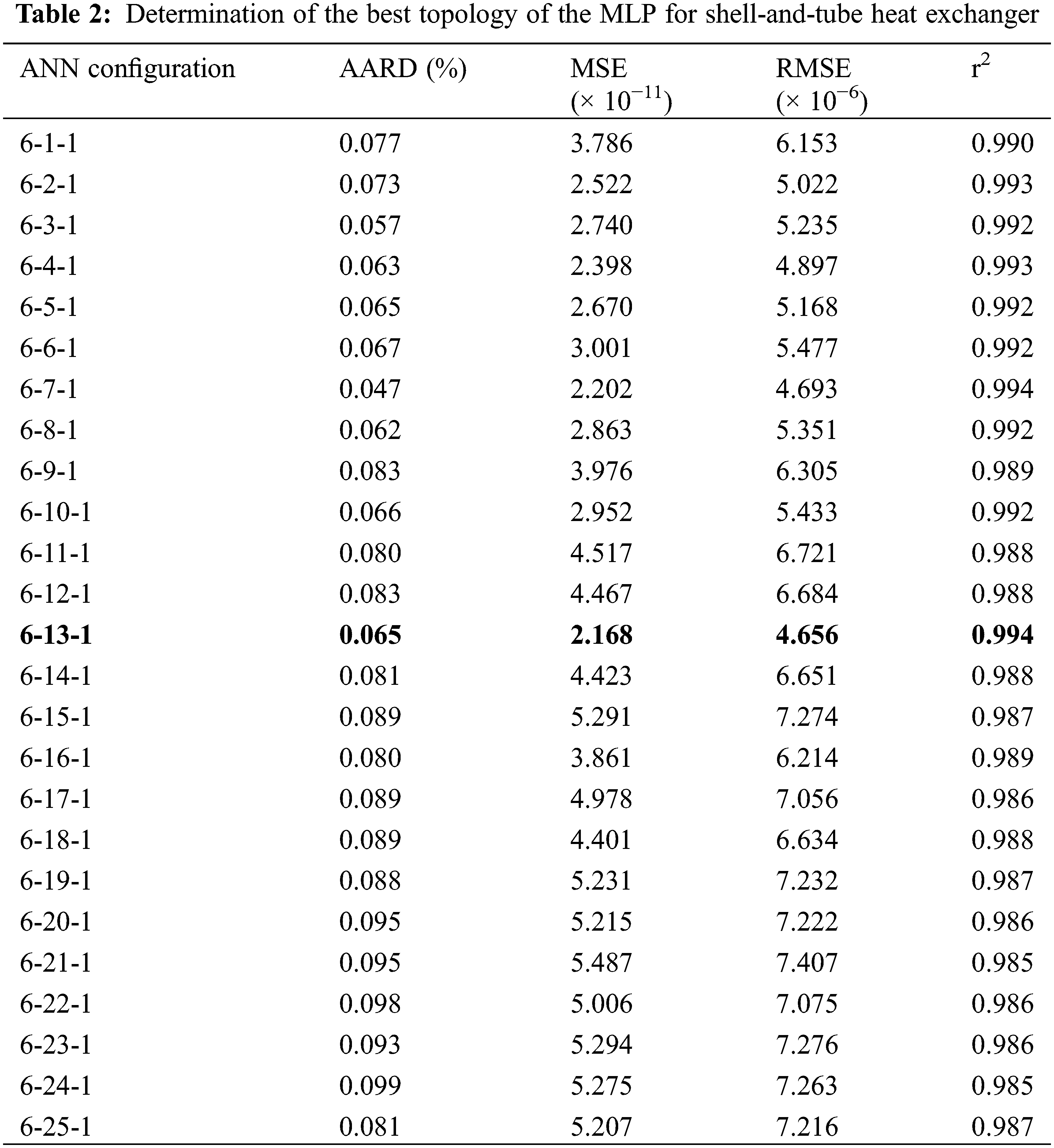
In this study, the optimal architecture for the fouling resistance prediction of heat exchanger is composed by a single hidden layer feed-forward network containing 13 hidden neurons with a tangent transfer function. This topology supplies the total AARD % = 0.065, MSE = 2.168 × 10⁻¹¹, RMSE = 4.656 × 10⁻⁶ and r2 = 0.994 for the shell-and-tube heat exchanger.
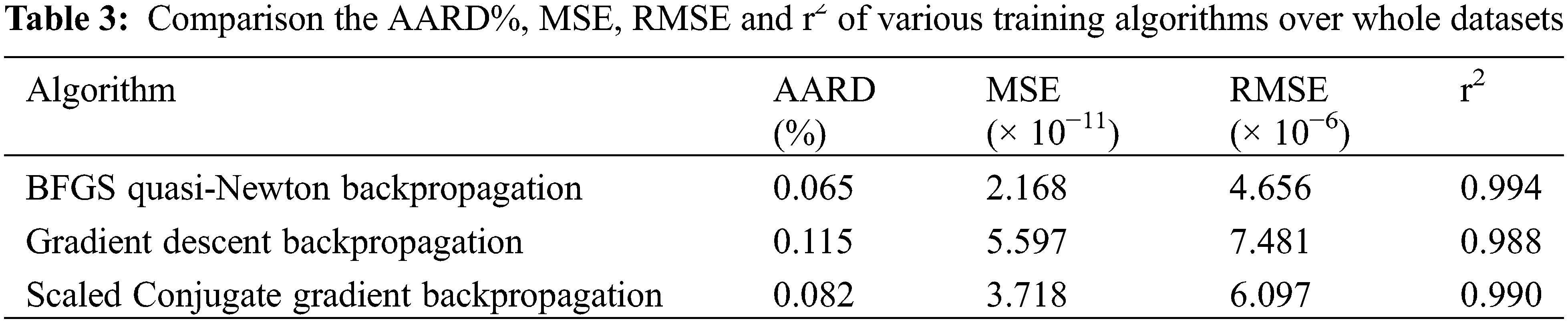
The MLP network with an optimal configuration is trained with various learning algorithms and a comparison between these algorithms are made based on their accuracy in order to find the algorithm which supplies a predictive precise accuracy.
Table 3 presents the global AARD %, the MSE, the RMSE and the r2 for three different algorithms. Based on the calculation precision, the BFGS quasi- Newton back-propagation offers the best performance. This algorithm presents the smallest total AARD %, MSE and RMSE and the highest value for r2. Consequently, the BFGS quasi-Newton back-propagation learning algorithm is the most appropriate learning algorithm for the considered task.
4.5 Model Evaluation for Prediction of Fouling Resistance
The MLP developed approach was trained validated and tested using 295 experimental data. Fig. 2 presents a comparison between the experimental datasets of the fouling resistance as a function of time and their corresponding estimated values by using ANN approach. According to this figure, it can be concluded that the ANN model predicts the experimental values of fouling resistance with an acceptable accuracy.
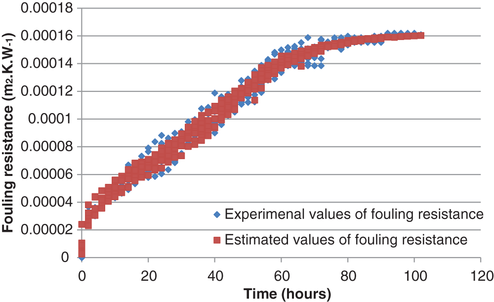
Figure 2: Performance of the proposed model for the prediction of fouling resistance on the datasets for shell-and-tube heat exchanger
In the present study, the ANN approach was used to predict the fouling resistance in shell-and-tube heat exchanger in diverse functioning conditions. The MLP developed network was trained using 295 experimental data and their accuracy was verified. The maximization of certain error indices used in this work has confirmed that 13 hidden neurons are sufficient for an accurate estimation of the considered variable associated for the studied heat exchanger. Furthermore, the BFGS quasi-Newton back-propagation approach is the best performed algorithm. The excellent prediction of the developed ANN model for the fouling resistance justifies the fact that it is a practical tool to integrate a mathematical model in order to estimate a cleaning schedule for the heat exchanger and control operation of the phosphoric acid concentration plant.
Funding Statement: The authors received no specific funding for this study.
Conflicts of Interest: The authors declare that they have no conflicts of interest to report regarding the present study.
1. Jradi, R., Marvillet, C., Jeday, M. R. (2020). Modeling and comparative study of heat exchangers fouling in phosphoric acid concentration plant using experimental data. Heat and Mass Transfer, 56(9), 2653–2666. DOI 10.1007/s00231-020-02888-9. [Google Scholar] [CrossRef]
2. Jradi, R., Marvillet, C., Jeday, M. R. (2020). Study of fouling in graphite blocks (cross flow) heat exchanger of phosphoric acid concentration process. Matec Web of Conferences, 330, 1038–1043. DOI 10.1051/matecconf/202033001038. [Google Scholar] [CrossRef]
3. Chambon, A., Anxionnaz-Minvielle, Z., Cwicklinski, G., Guintrand, N., Buffet, A., Vinet, B. (2020). Shell-and-tube heat exchanger geometry modification: An efficient way to mitigate fouling. Heat Transfer Engineering, 41(2), 170–177. DOI 10.1080/01457632.2018.1522093. [Google Scholar] [CrossRef]
4. Majdi, H. S., Alabdly, H. A., Hasan, B. O., Hathal, M. M. (2019). Oil fouling in double-pipe heat exchanger under liquid-liquid dispersion and the influence of copper oxide nanofluid. Heat Transfer, 48(5), 1963–1981. DOI 10.1002/htj.21473. [Google Scholar] [CrossRef]
5. Kamble, L. V., Pangavhane, D. R., Singh, T. P. (2014). Heat transfer studies using artificial neural network–A review. International Energy Journal, 14(1), 25–42. [Google Scholar]
6. Iyengar, A. S. (2015). Thermal analysis of shell and tube heat exchangers using artificial neural networks. Ethiopian Journal of Science and Technology, 8(2), 107–120. DOI 10.4314/ejst.v8i2.5. [Google Scholar] [CrossRef]
7. Du, X., Chen, Z., Meng, Q., Song, Y. (2020). Experimental analysis and ANN prediction on performances of finned oval-tube heat exchanger under different air inlet angles with limited experimental. Open Physics, 18(1), 968–980. DOI 10.1515/phys-2020-0212. [Google Scholar] [CrossRef]
8. Davoudi, E., Vaferi, B. (2018). Applying artificial neural networks for systematic estimation of degree of fouling in heat exchangers. Chemical Engineering Research and Design, 130, 138–153. DOI 10.1016/j.cherd.2017.12.017. [Google Scholar] [CrossRef]
9. Biyanto, T. R. (2016). Fouling resistance prediction using artificial neural network non-linear auto-regressive with exogenous input model based on operating conditions and fluid properties correlations. AIP Conference Proceedings, 1737(1), 1–7. DOI 10.1063/1.4949304. [Google Scholar] [CrossRef]
10. Jradi, R., Fguiri, A., Marvillet, C., Jeday, M. R. (2019). Tubular heat exchanger fouling in phosphoric acid concentration process. Inverse Heat Conduction and Heat Exchangers. London: IntechOpen. DOI 10.5772/intechopen.88936. [Google Scholar] [CrossRef]
11. Jradi, R., Fguiri, A., Marvillet, C., Jeday, M. R. (2019). Experimental analysis of heat transfer coefficients in phosphoric acid concentration process. Journal of Statistical Mechanics: Theory and Experiment, 2019(8), 1–15. DOI 10.1088/1742-5468/ab2531. [Google Scholar] [CrossRef]
12. Tandiroglu, A. (2016). Artificial neural network approach for transient forced convective heat transfer optimization. International Journal of Mechanical Engineering and Applications, 4(6), 212–225. DOI 10.11648/j.ijmea.20160406.12. [Google Scholar] [CrossRef]
 | This work is licensed under a Creative Commons Attribution 4.0 International License, which permits unrestricted use, distribution, and reproduction in any medium, provided the original work is properly cited. |