| Fluid Dynamics & Materials Processing |
DOI: 10.32604/fdmp.2022.019799
ARTICLE
Determination of the Cement Sheath Interface and the Causes of Failure in the Completion Stage of Gas Wells
1CNOOC Research Institute, Beijing, 100027, China
2Yangtze University, Wuhan, 430100, China
*Corresponding Author: Huanqiang Yang. Email: yanghuanqinagtze@163.com
Received: 15 October 2021; Accepted: 12 January 2022
Abstract: The bonding quality of the cement sheath interface decreases during well completion because of the change in the casing pressure. To explore the root cause of such phenomena, experiments on the mechanical properties and interface bonding strength of a cement sheath have been carried out taking the LS25-1 high-temperature and high-pressure (HTHP) gas field as an example. Moreover, a constitutive model of the cement sheath has been defined and verified both by means of a full-scale HTHP cement sheath sealing integrity evaluation experiment and three-dimensional finite element simulations. The results show that the low initial cementing surface strength is the root cause of cement sheath interface bonding failure. When the pressure in the casing exceeds a certain limit, the stress caused by the change in the internal pressure in the casing is transmitted to the cement sheath, resulting in the degradation of the interface stiffness of the cement sheath. However, with an increase in the casing wall thickness, the stress transmission capacity decreases. Therefore, it is concluded that improving the interfacial cementing strength, appropriately increasing the casing wall thickness and increasing the initial stress of the cement sheath are the keys to ensuring the sealing integrity of the cement sheath in high-temperature and high-pressure gas wells.
Keywords: Gas well completion; cement sheath; sealing failure; interfacial bonding strength; damage plasticity model
With the increase in exploration and development of natural gas resources, an increasing number of high-temperature and high-pressure gas wells are found [1–3]. In the completion stage of high-temperature and high-pressure gas wells, many annulus pressure phenomena of high-pressure gas wells caused by the decline of the interlayer sealing quality of the cement sheath have brought severe challenges to the safety production of petroleum and gas wells [4–6]. The sealing failure modes of cement sheath mainly include cement sheath body failure and cement sheath interface cementation failure [7,8]. For the failure of cement sheaths, sealing failure experiments of cement sheaths under cyclic loading in casings by using a small-size evaluation device has been carried out, and tensile failure, radial failure and other failure forms of cement sheaths have been obtained [9,10]. A finite element numerical model considering the elastic-plastic constitutive relationship of the cement sheath was established, and the elastic-plastic failure behavior of the cement sheath was analyzed. The elastic-plastic model is mainly based on the compressive stress-strain curve of cement stone, without considering the tensile failure process of the cement sheath [11–13]. Therefore, the concrete damage plastic (CDP) model for the construction of the constitutive model of cement stone has been introduced. Based on the compressive stress-strain curve and tensile load-displacement curve of the cement sheath, the compression and tensile failure process of the cement sheath under variable casing pressure is analyzed. For the study of the cement sheath interface cementation failure law, a cement sheath interface failure experiment under cyclic loading in the casing by using a large-scale cement sheath sealing integrity evaluation device was carried out. The plastic deformation of the cement sheath caused by cyclic loading is considered the main cause of cement sheath interface sealing failure [14]. By considering the initial stress of the cement sheath, the influence law of the change in well pressure on the sealing failure of the cement sheath was studied. It is considered that the large reduction in well pressure leads to a microannular gap at the cement sheath interface [15]. By considering the temperature effect, the thermal solid coupling model of casing cement sheath formation has been established, and the influence of temperature and pressure variation in the wellbore on the interface cementation coefficient has been studied [16,17]. The elastic-plastic analysis model of the casing cement sheath surrounding rock combination based on the Mohr-Coulomb criterion has been established to judge whether a microannulus is formed based on the interfacial tension and provide the calculation formula of the microannulus [18]. The elastic-plastic analysis model concluded that a bonding force of 0.1 MPa is exerted at the cementing interface, the mechanism of the microannulus was revealed through testing and numerical simulation, and the calculation method of the cementing microannulus was formed [19]. The above research lacks a quantitative description of cement sheath interface cementation, without considering the failure process of the cement sheath interface and the influencing factors of interface cementation failure. How to quantitatively describe the interfacial cementation characteristics of cement sheaths and use an appropriate model to describe the cementation characteristics is the key to analyzing and studying interfacial cementation failure. The cohesive model is used to simulate the first and second cementing interfaces, ignoring the influence of the initial stress of the cement sheath. The influence law of the formation rock stiffness and casing eccentricity on the interface cementing failure has been studied. The cohesive model was used to simulate the first cementing interface, and the annulus channeling law has been studied [20]. In the above studies, the cement sheath interface bonding strength values were used as the cohesive model parameters [21,22]. The cementation strength parameters used in the above references are shown in Table 1.
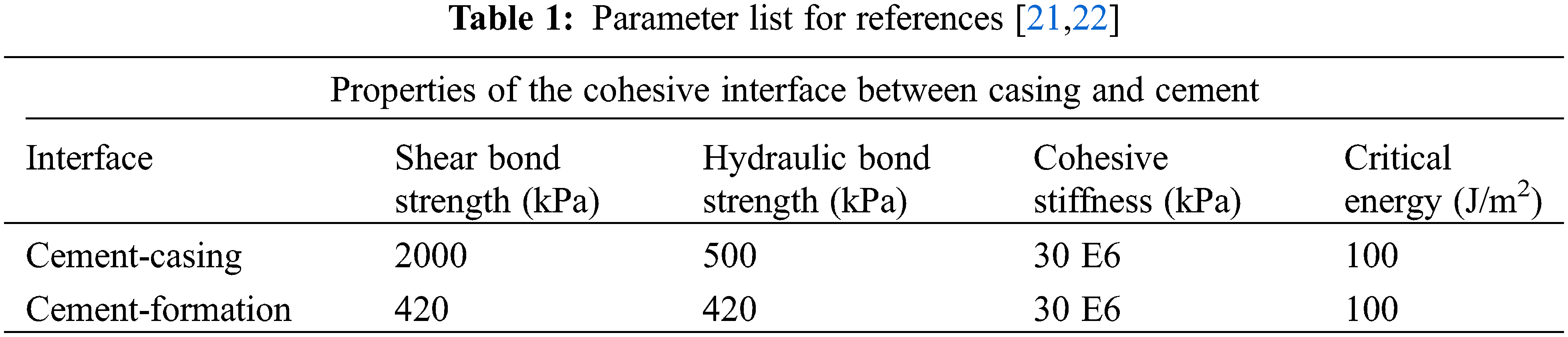
Due to the limitations of cement slurry systems, casing properties, curing temperature and test conditions, the cited interface bonding strength data cannot accurately reflect the real interface bonding in cementing engineering. As a result, the simulation results cannot be used to accurately analyze the cement sheath interfacial bonding failure process and influencing factors.
Therefore, based on the self-developed high-temperature and high-pressure cement sheath interface bonding strength test device, the cement sheath interface bonding strength experiment under high-temperature and high-pressure conditions is carried out, the damage plastic model of the cement slurry system and the cohesive model of the cement sheath interface are constructed, and the three-dimensional numerical model of cement sheath interface bonding failure is established. The purpose is to reveal the influencing factors and laws of cement sheath interface cementation failure and to provide theoretical guidance for the integrity evaluation of the high-temperature and high-pressure cementing cement sheath [23–34].
2 Construction of the Cement Sheath and Its Interface Constitutive Model
2.1 Mechanical Test of Cement Stone
The cement slurry system used in the LS25-1 gas field is composed of grade G oil well cement, heat stabilizer C-SI880 M, self-repairing material C-SH1, anti-channeling reinforcing agent C-GS12S, latex C-GS21, dispersant C-F46 L, high-temperature retarder C-R40 L, medium temperature retarder C-R21 L, etc. The cement slurry was prepared according to the GB/T 19139-2012 method for oil well cement [35]. The prepared cement slurry has a density of 2.35 g/cm3. Standard cube specimens of 50.8 × 50.8 × 50.8 mm3 and three-point bending tensile test specimens of different sizes were prepared according to the high-temperature and high-pressure conditions of the cement sheath in the gas field. The specimen was cured at a temperature of 120°C, and a pressure of 20 MPa. The load-displacement curve of different sizes, the compressive yield stress inelastic strain and tensile test, the compressive stress-strain curve of the cement sheath are obtained according to the GB 50010-2010 code for the design of concrete structures.
Compression failure and tensile failure, which can be described by the concrete damage plastic (CDP) model, are two types of cement sheath body failure caused by complex wellbore temperature and pressure changes. The data from each point on the stress-strain curve of the cement sheath under uniaxial compression are substituted into the formula to calculate the damage factor at this point, which can be input into Abaqus. The damage factor is calculated as follows:
where αa and αd are parameter values of the rising and falling sections of the stress-strain curve under uniaxial compression of the cement sheath; fc* is the uniaxial compressive strength of the cement sheath, and its value can be taken as fc, fck or fcm for actual structural analysis; εc is the peak compressive strain of the cement sheath corresponding to uniaxial compressive strength fc*; dc is a damage evolution parameter of the cement sheath under uniaxial compression.
To reduce the error of the numerical simulation results, the constitutive parameters of the CDP model are calibrated using the experimental data, and the CDP model parameters consistent with the experimental results are obtained, including the elastic modulus of cement stone, 4.92 GPa; Poisson’s ratio, 0.28; the compressive strength, 23.6 MPa; the compressive yield strength, 19.8 MPa; the tensile strength, 1.65 MPa; the expansion angle, 30°C; the fracture energy, 25 N/mm; and the fracture factor, 0.667.
2.2 Cement Sheath Interface Cohesion Model
2.2.1 Cement Sheath Interface Model
The cemented interface between the cement sheath and casing as well as between the cement sheath and formation is the weak link of cement sheath sealing. How to describe the interface characteristics is the basis for realizing the failure analysis of the cemented interface. The cohesive model has important advantages in the simulation of bimaterial interface fracture or separation, as it can describe the material tensile failure and shear failure of the experiment, measure the cementing strength, and directly input data of Abaqus. The cohesive force model is the largest characteristic of how tensile stress and relative displacement relate to each other. Different cohesive force models corresponding to the different cohesive force-relative displacement functions can accurately simulate the nature of the casing and cement sheath interface. In addition, compared with the cohesive force model, the cementation interface simulated by other methods, such as interaction force, is relatively simple and does not adhere to reality. Therefore, in this paper, the cohesive model is used to simulate the bimaterial interface between the casing cement sheath and cement sheath formation. The constitutive relationship expression of the cohesive model is as follows [8–20]:
where σ is the stress, δ is the relative displacement, K is the interface stiffness coefficient, n represents the normal direction, and s and t represent the two tangential directions.
For the interface failure analysis of the cement sheath carried out in this study, the secondary nominal stress criterion under the mixed mode in the cohesive model is used to judge the failure. The judgment criteria are as follows:
where σno, σso, and σto represent the hydraulic bonding strength and mechanical bonding strength of the cement sheath interface, respectively.
When Eq. (6) is satisfied, the cement sheath interface begins to suffer damage. The damage law, as illustrated in Fig. 1, describes the degradation and final failure of the cement sheath interface in the normal direction. The OA section is a linear elastic stage in which the cement sheath interface is not damaged. When the cement sheath interface stress σn increases to σno, the cement sheath interface begins to sustain damage, and the AB section is the damage softening stage of the interface, in which the interface stiffness is degraded, but the interface is not completely stripped. When point B is reached, the interface is completely stripped, and a microannular gap appears at the cement sheath interface. Assuming that the critical fracture energies in the two tangential directions are equal when the cement sheath interface is separated, that is, GSC = GTC, the BK fracture energy criterion is as follows:
where GS = GS + GT is the fracture energy in the normal direction, GSC is the fracture energy in the tangential direction, and in the mixed mode, GT = GS + GN, and η is the cohesive performance parameter.
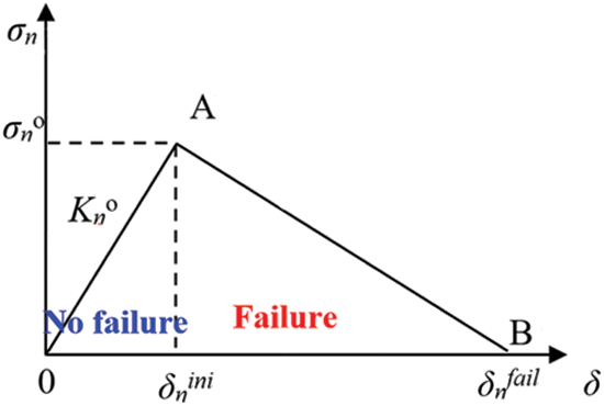
Figure 1: Traction separation law of linear softening
2.2.2 Experimental Test of the Interfacial Bonding Strength of the Cohesive Model
The judgment criterion of Eq. (6) contains the mechanical bonding strength and hydraulic bonding strength of the cement sheath interface, which are the key parameters for determining whether the interface fails. Therefore, the test results of the interface bonding strength have a decisive impact on the analysis results of cement sheath interface bonding failure. Given that the existing cement sheath interface bonding strength cannot be tested under high-temperature and high-pressure curing conditions, a high-temperature and high-pressure cement sheath interface bonding strength test device have been independently developed [36,37]. To accurately measure the interfacial bonding strength, the following methods are used: preparing cement slurry according to the formula in Section 1, selecting a steel pipe with the same roughness as the real casing to simulate the inner casing, and heating the device to realize curing under high-temperature conditions. After curing, it is not necessary to remove the test specimen and directly test the interfacial bonding strength to prevent the influence of temperature change on the bonding strength. Fig. 2 depicts the construction of the test device.
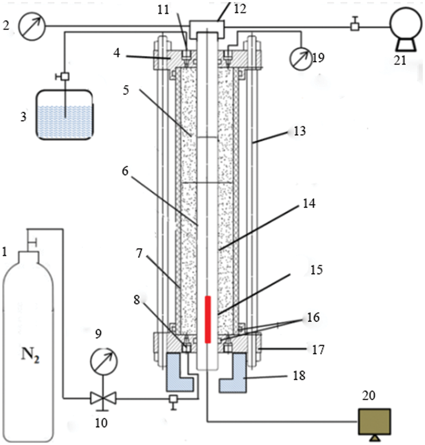
Figure 2: Cement sheath interface bonding strength test device
The uniaxial compression method and the gas channeling method were used to assess the mechanical bond strength and hydraulic bond strength of the first interface of the cement sheath under high-temperature and high-pressure curing (210°C, 15 MPa).
The uniaxial compression method for measuring the mechanical bond strength is as follows: (1) Prepare the slurry and maintenance in the device, (2) Perform uniaxial compression experiment in the device, and after the experiment, pressurize it on the pressure pad. When the pressure is higher than the cement sheath first mechanical cementation strength of the interface, the inner casing, and cement sheath are removed.
The gas channeling method for hydraulic cementing strength test and measurement is as follows: (1) Place the magnet cover on the air inlet at the bottom of the device to prevent the slurry into blocks, (2) prepare the slurry and maintain it in the device, (3) after the completion of the increasing pressure in the intake, keep maintenance until the gas channeling in front of the maximum pressure for hydraulic cementing strength. The occurrence of gas channeling is marked by a sudden and rapid decrease in air intake pressure.
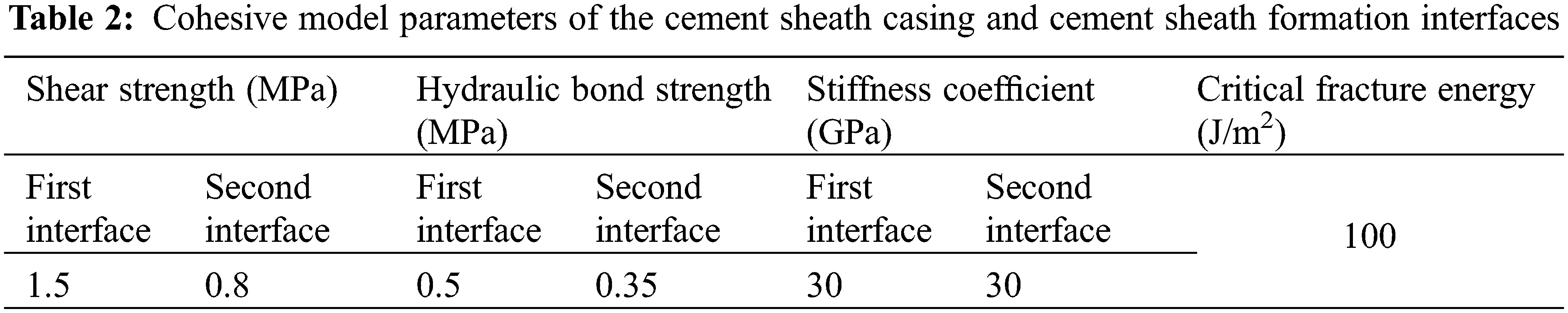
The cementation strength of the second interface of the cementing, the interface stiffness of the cement sheath and the critical fracture energy in Eq. (7) can be obtained by adopting the data, and the cohesive model parameters of the interface between the cement sheath casing and cement sheath formation are obtained, as shown in Table 2.
3 Finite Element Numerical Simulation Process
3.1 Finite Element Numerical Model
Taking the LS25-1 gas field as an example, the casing and formation are set as elastic materials. The casing has an elastic modulus of 210 GPa and a Poisson’s ratio of 0.3, whereas the formation has an elastic modulus of 25 GPa and Poisson’s ratio of 0.32. The cement sheath is described by the CDP model, and the model parameters have been described in Section 1. The two interfaces of the casing cement sheath and cement sheath formation are described by the cohesive model, and the corresponding model parameters are listed in Table 2.
3.1.2 Geometric Model and Grid Model
The geometric model of cement sheath sealing failure contains the casing, cement sheath, formation, casing cement sheath interface, and cement sheath formation interface. According to the well structure characteristics of the LS25-1 gas field, the bit size is 215.9 mm. A P-110 casing with a wall thickness of 12.65 mm and a diameter of 177.8 mm is adopted. Considering the possible casing eccentricity, the set casing eccentricity (e) are 0%, 10%, 20%, 30%, 40%, 50%, and 60%, and the influence of the boundary effect can be eliminated when the formation width is 5-fold greater than the borehole diameter [38,39]. Therefore, the length, width, and height of the formation are set as 2 × 2 × 0.5 m3, and the established geometric model is shown in Fig. 3.
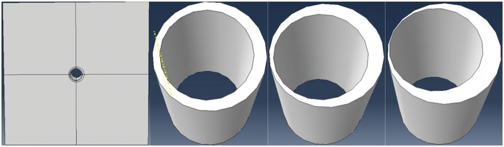
Figure 3: Geometric model of cement sheath sealing failure
As the cement sheath is the weak link of the casing cement sheath formation combination, the formation and casing adopt the method of distributing seeds by shifting to the cement sheath. The casing, cement sheath and formation adopt the C3D8R unit, whereas the interface between wells I and II adopts the COH3D8 unit. According to the sensitivity analysis of the grid density, when the number of model grid cells is more than 24960, the grid density has little effect on the calculation results. Therefore, to reduce calculation cost, 24960 grid cells are chosen, and the formed grid model is shown in Fig. 4.
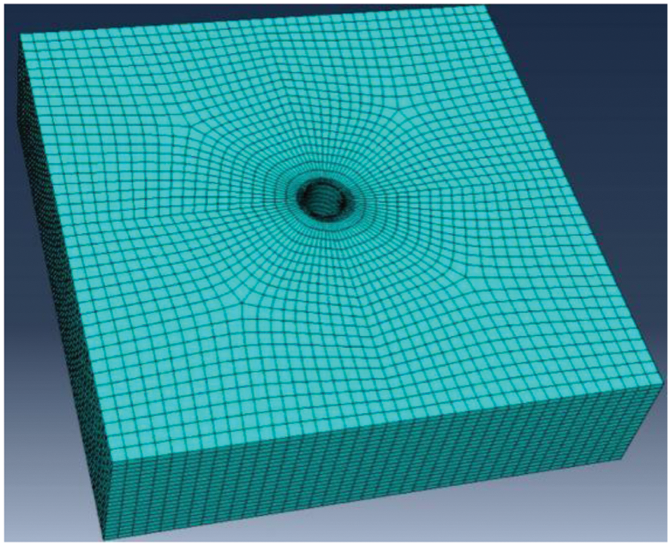
Figure 4: Grid model
3.1.3 Boundary Conditions and Failure Criteria
The initial conditions of the model are set according to the in-situ stress field after cementing, and the initial in-situ stress field is applied on each calculation node of the casing cement sheath formation rock. The boundary conditions are set according to the displacement change of the model in the calculation process. The x-, y- and z-direction displacement constraints are applied to the plane perpendicular to x, y, and z, respectively. According to the well completion process, the calculation is divided into the following two analysis steps. In the in-situ stress balance step, the initial stress of the cement sheath is applied and changed. In the loading step, the change in pressure in the casing during well completion is realized.
The failure forms of the cement sheath include tensile failure, compression failure and cement sheath interface cementation failure. The circumferential compressive failure coefficient DAMAGEC (compression failure occurs when DAMAGEC = 1, and compression damage occurs when 0 < DAMAGEC < 1) and tensile failure coefficient DAMAGET (tensile failure occurs when DAMAGET = 1, and tensile damage occurs when 0 < DAMAGET < 1) are adopted to judge the failure of the cement sheath body. The cement sheath interface cementation failure can be judged by SDEG, which is the cement sheath interface stiffness degradation coefficient (interface cementation failure occurs when SDEG = 1, and interface damage occurs when 0 < SDEG < 1).
Based on the above cement sheath CDP model parameters and the cohesive parameters of the first and second cementing interfaces, a three-dimensional finite element numerical model of cement sheath sealing failure under experimental conditions is established. According to the actual formation mechanical parameters, a simulated formation with a diameter of 400 mm is prepared with the ratio of cement:yellow sand:water = 1:3:0.4. The elastic modulus of the simulated formation specimen is 19.6 GPa, and Poisson’s ratio is 0.27.
The numerical simulation results are verified by using the developed full-scale high-temperature and high-pressure cement sheath sealing integrity evaluation device (as shown in Fig. 5). The device is composed of the wellbore simulation system, the pressure application and control system, the temperature application and control system as well as the sealing system. The wellbore simulation system consists of a 177.8 mm casing, 220 mm cement sheath and 400 mm formation. The eccentric ring can be used to make test specimens with 20%, 40%, and 60% casing eccentricity. The pressure application and control system can apply pressure in the casing (0–70 MPa), confining pressure (0–70 MPa), annulus trap pressure (0–40 MPa), and gas channeling pressure (0–40 MPa). The temperature application and control system is used to apply the actual formation temperature to the system. The temperature application range is −5°C to 220°C, and the accuracy is ±0.1°C. The sealing system is used to seal the above four pressures and is composed of sealing rings of different sizes and fluororubber sleeves.
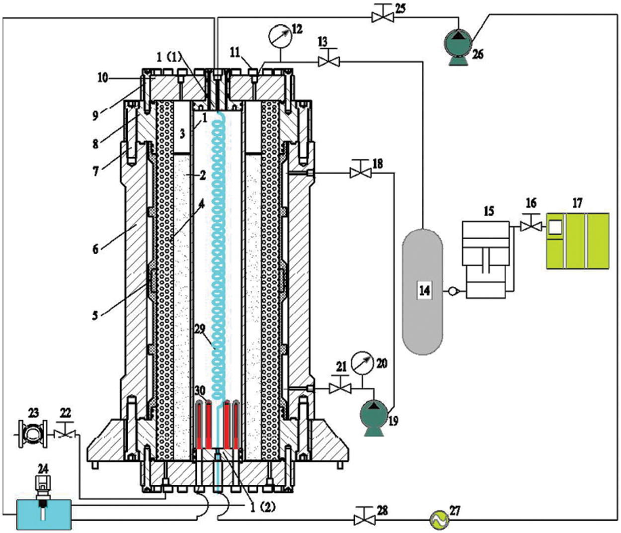
Figure 5: Full-size high-temperature and high-pressure cement sheath sealing integrity evaluation device
The curing temperature of the cement slurry is set at 210°C, and the initial stress of the cement sheath is controlled through the application and release of annulus trap pressure. To better compare the experimental results and numerical simulation results, the initial stress of the cement sheath is not considered in the cement sheath interface failure experiment and numerical modeling based on the experimental conditions. The gas channeling method is used to verify whether the cement slurry interface is invalid. The upper and lower end faces of the cement sheath are set with a pressure difference of 0.1 MPa. With increasing pressure in the casing, when gas emerges from the upper-end face, the cement sheath interface bonding is completely invalid. As shown in Fig. 6, after the cement sheath interface bonding fails, the casing is removed from the inner interface of the cement sheath.
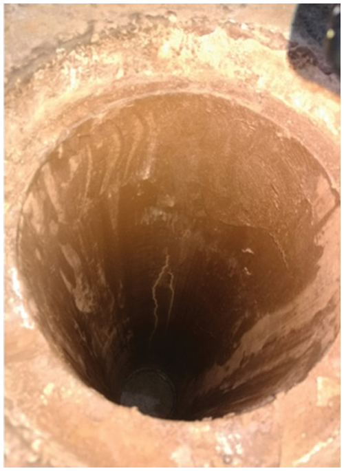
Figure 6: Peeling of the casing cement sheath interface after complete failure of the cementation interface
The device is characterized by: (1) exact size match with the actual hole; (2) use of a simulated formation cast in concrete as the experimental material, avoiding the disadvantages of equivalent substitution in the use of similar equipment; (3) resistance to high temperature and pressure, and using the device can simulate the complex environment of the underground. Therefore, the result of the measurement is more accurate and practical. Table 3 compares the experimental and numerical simulation findings of three casing eccentricity rates of 20%, 40%, and 60% based on the experimental method.
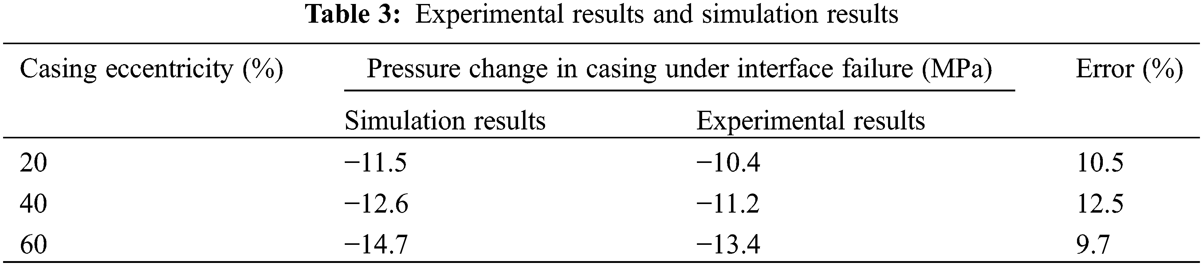
The maximum error is 12.5%, and the average error is 10.9%, showing that the CDP model and cohesion model for the constitutive relationship between cement and cement sheathing are correct and appropriate.
4 Discussion of the Failure Factors of Cement Sheath Interface Cementation
4.1 Cause Analysis of Cementing Quality Decline Caused by Well Completion Operation
The LS25-1-xx well was used as an example to explore and analyze the problem of declining quality of interfacial cementing in the completion stage of LS25-1 gas field. The well is a vertical well with a vertical depth of 4426.86 m, a cement return depth of 4096.7 m, a sealing length of 330.16 m, a reservoir temperature of 213°C, and a bottom hole pressure of 99 MPa. Limited by displacement and small annular clearance, the initial cementing quality of the well is poor, and an obvious decline in cementing quality occurs during well completion. The corresponding well completion process is divided into three stages. The pressure in the casing increases by 15–30 MPa in the casing pressure test stage, the well completion fluid density in the negative pressure test stage decreases from 2.27 to 1.8 g/cm3, and the pressure in the casing increases by 48 MPa in the circulating well killing stage.
The main role in preventing mechanical damage to the cement sheath is the mechanical bonding strength of the cement sheath interface, and the main role in inhibiting annulus channeling is the hydraulic bonding strength of the cement sheath interface. Therefore, the mechanical bonding strength of the casing cement sheath interface is set at 0.25, 0.5, 0.75, 1, 1.25, and 1.5 MPa, respectively, and the mechanical bonding strength of the cement sheath formation interface is 50% of that of the casing cement sheath interface. Three analysis steps are set according to the pressure change value in the casing corresponding to the well completion process in this area. Based on the finite element numerical model of cement sheath sealing failure, the pressure change in the casing with the cohesive stiffness degradation coefficient SDEG of the casing cement sheath and cement sheath formation reaching 1 is calculated, as shown in Fig. 7.
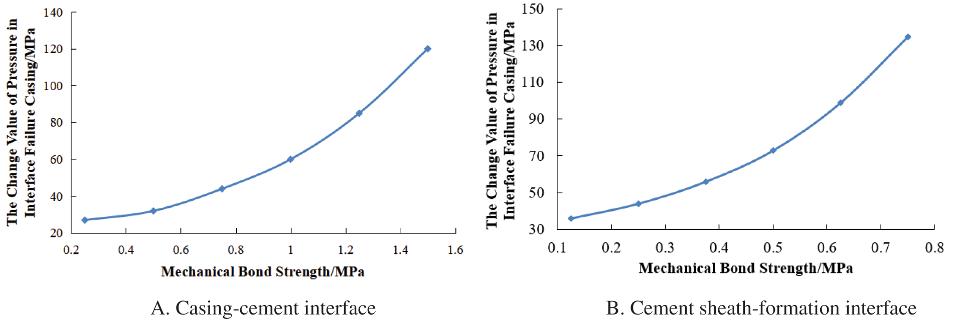
Figure 7: Pressure increase in casing due to cement sheath interface failure
As seen from Fig. 7, with the increase in the mechanical bonding strength of the cement sheath interface, the change value of the pressure in the casing with the failure of the cement sheath and cement sheath formation interface increases in a parabola, and the change value of the pressure in the casing required for the failure of the cement sheath formation interface is significantly larger. Therefore, the interface where the cementation quality decreases during well completion is mainly the casing cement sheath interface. The failure law of the casing cement sheath interface is analyzed below.
When the mechanical bond strength of the casing cement sheath reaches 1.5 MPa, the pressure change in the casing with interface failure can reach 114 MPa. Therefore, the increase in mechanical bond strength can effectively prevent stress damage at the cement sheath interface. When the maximum pressure change in the casing in the completion operation of the LS25-1 gas field is within 38–52 MPa, the corresponding mechanical cementing strength is from 0.6–0.8 MPa, which is only 1/3–1/2 of the experimental test results, indicating that the initial cementing quality of the gas field is poor. When the mechanical bond strength is 0.8 MPa, the calculation results of each analysis step are shown in Figs. 8 and 9.
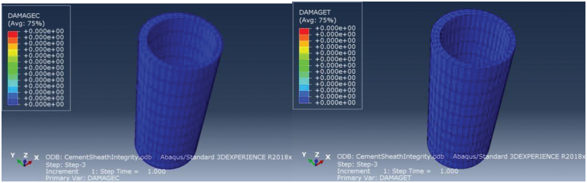
Figure 8: Damage of the cement sheath body at each stage of well completion
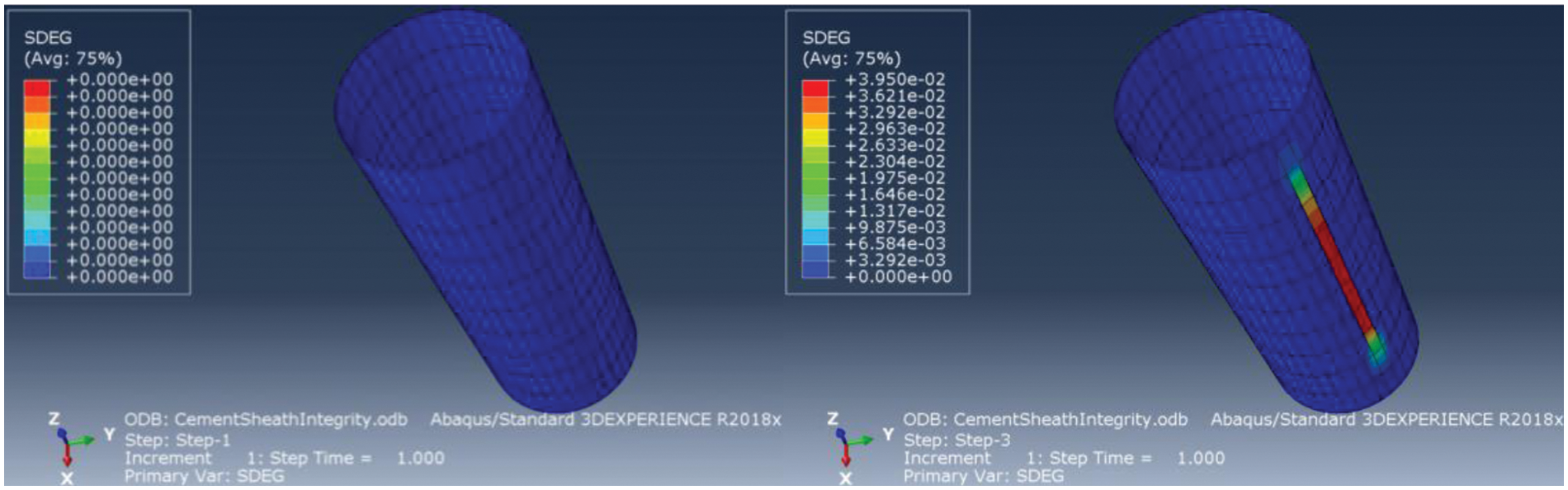
Figure 9: Cementing failure of the cementing interface at each stage of well completion
Fig. 8 shows the damage of the cement sheath body in each stage of well completion. In the stages of the casing pressure test, negative pressure test and circulating well killing, the compression failure coefficient DAMAGETC and tensile failure coefficient DAMAGET of the cement sheath body are 0, indicating that the above well completion process will not cause damage to the cement sheath body.
Fig. 9 shows the cement sheath interface cementation failure at each stage of well completion. In the casing pressure test and negative pressure test stage, the cement sheath interface stiffness degradation coefficient SDEG is equal to 0, indicating that interface cementation quality does not decline, as shown in the left figure of Fig. 9. In the circulating well killing stage, when the pressure in the casing increases by 48 MPa, a 3.95% degradation of cementation interface stiffness occurs along the direction of minimum horizontal in-situ stress, as shown in the right figure of Fig. 9. Therefore, the change in pressure in the casing during circulating well killing causes a decline in cementation quality at the cementing interface.
In the negative pressure test, the bottom hole pressure was reduced by approximately 20 MPa, and the initial stress of the cement sheath was set to 3 MPa. Fig. 10 shows the numerical simulation results.
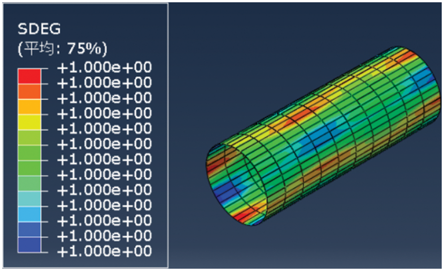
Figure 10: Calculation results of the negative pressure test
Cementing failure will occur at the bottom of the well when a negative pressure test is performed at the current cementing strength. To determine the cementing strength requirement for the cement sheath under current conditions, set the well consolidation strength to 1, 2, 3, 4 and 5 MPa and calculate the critical pressure reduction value when the cementing failure occurs. The calculation results are shown in Fig. 11.
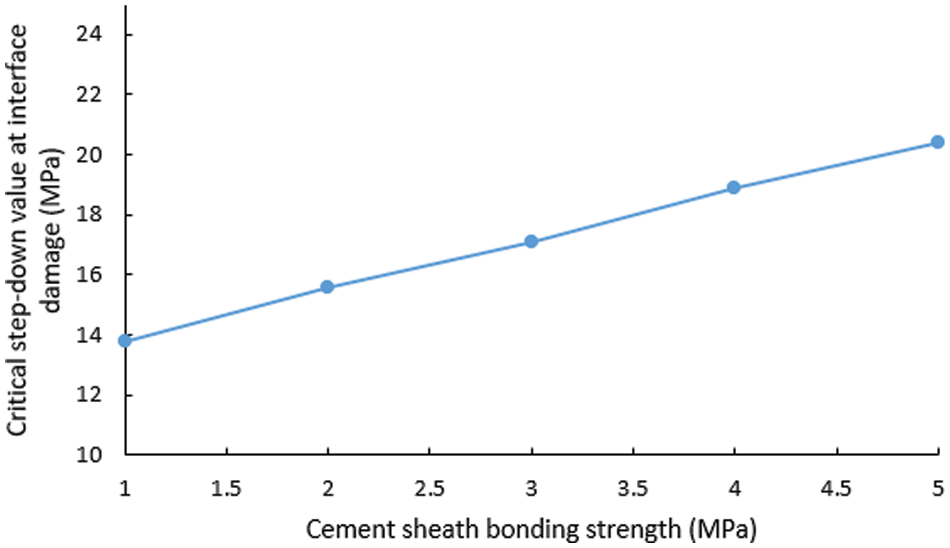
Figure 11: Corresponding critical pressure reduction values under different cementing strengths
According to the calculation, if the pressure in the casing is lowered by 14–16 MPa with the existing cement strength, cement failure will occur, so it cannot meet the cementing requirements. As a result, the cement slurry system must be optimized to enhance the cement strength to 4–5 MPa.
Overall, the poor initial cementing quality of the LS25-1 well, combined with the inadequate cement bond strength, led to the failure of the cement bond in this well.
4.2 Effect of Casing Wall Thickness on Cement Sheath Interface Cementation Failure
Because of the great differences in mechanical properties between the casing and cement sheath, under the same pressure change in the casing, casings with different wall thicknesses have different effects on the stress distribution of the casing cement sheath formation. On the premise of certain initial cementing quality, to explore the influence of casing wall thickness on cement sheath interface cementation failure, the influence of a pressure change in casing on cement sheath interface cementation failure during well completion of 177.8 mm casing with 9.19, 10.36 and 12.65 mm wall thickness is calculated, and the results are shown in Fig. 12.
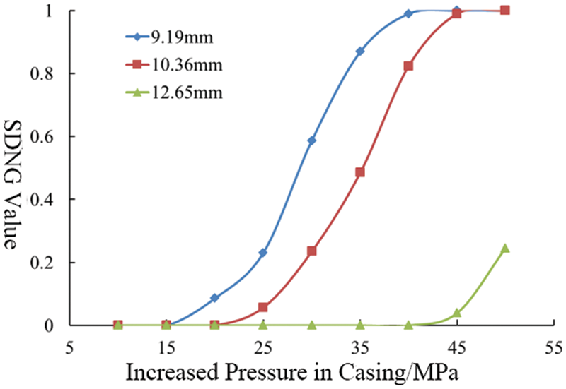
Figure 12: Effect of different casing wall thicknesses on cement sheath interface cementation failure
Fig. 12 shows that when the casing pressure test is between 15–30 MPa, the cement sheath interface bonding stiffness corresponding to casing wall thicknesses of 9.19 and 10.36 mm degrades, while the 12.65 mm casing wall thickness protects the integrity of the cement sheath bonding interface. These results show that the thin-walled casing has difficulty protecting the cement sheath bonding interface. With the increase in casing wall thickness, the stress caused by the pressure change in the casing is difficult to transfer to the cement sheath, and the cement sheath interface stiffness will not deteriorate. When the pressure change in the casing increases to 48 MPa, the stress distribution of the cohesive unit at the cement sheath interface is shown in Fig. 13.
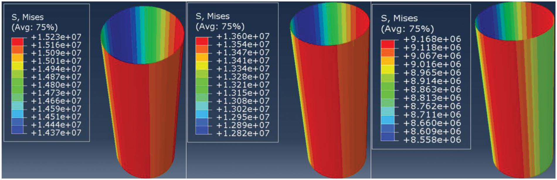
Figure 13: Stress distribution of cohesive elements at the cement sheath interface corresponding to different casing wall thicknesses
With increasing casing wall thickness, the stress transmitted to the cement sheath interface decreases. Therefore, for gas wells with severe annulus pressure, the wall thickness of the production casing should be appropriately increased.
4.3 Effect of the Initial Stress of the Cement Sheath on the Cementation Failure of the Cement Sheath Interface
The initial stress of the cement sheath refers to the stress existing on the cement sheath after the cement slurry is waiting to set and the cement stone performance is stable, which is mostly expressed as radial effective stress. It is concluded that when the cement slurry returns to the ground, the initial stress at the second interface of the cement sheath is equal to the hydrostatic column pressure before the cement slurry solidifies minus the formation pore pressure [40,41]. Affected by the structure of the annulus slurry column and the sealing length of the cement slurry, the initial stress of the cement sheath is different. Taking the LS25-1 gas field as an example, based on cementing design parameters and pore pressure data, the initial stress of the cement sheath applied to the second interface of cementing is calculated to be 0–5 MPa, as shown in Fig. 14, which shows the distribution of cement sheath stress at initial stresses of 1, 3 and 5 MPa at the second interface σi. The initial stress on the second interface of the cement sheath is slightly greater than that on the first interface. The calculated cement sheath interface cementation failure is shown in Fig. 15.
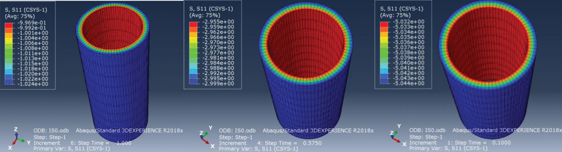
Figure 14: Initial effective stress distribution on the cement sheath
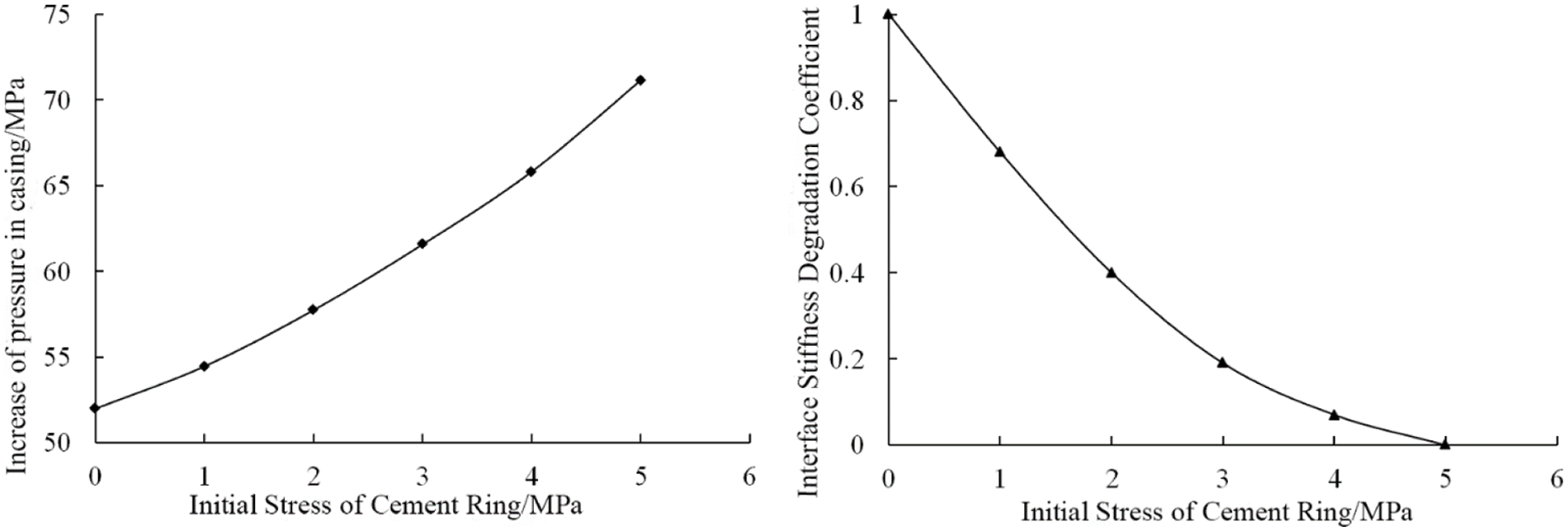
Figure 15: Effect of the initial stress of the cement sheath on the cementation failure of the cement sheath interface
As seen from Fig. 15, with increasing initial stress of the cement sheath, the pressure change in the casing increases when the interface SDEG reaches 1. When the pressure increase in the casing is 52 MPa, the interface SDEG decreases with increasing initial stress of the cement sheath from Fig. 15, indicating that an increase in the initial stress of the cement sheath is helpful to improve the interface integrity of the cement sheath.
This is because the initial stress acting on the cement sheath points to the casing. When the pressure in the casing increases, the generated stress must first offset part of the initial stress. Therefore, with increasing initial stress in the cement sheath, the offset pressure in the casing increases. The initial stress of the cement sheath can be increased by increasing the fluid column pressure of the annulus slurry and increasing the sealing length of the cement slurry.
1. Based on the 3D finite element numerical simulation of cement annular interface cementing failure, the main reasons for the degradation of this interface cementing quality at the completion stage are analyzed. The results show that the initial interfacial cementing strength of the LS25-1 gas field is 0.6–0.8 MPa, which is only 1/2 to 1/3 of the experimental results. Meanwhile, the cementing strength of the current cement slurry system cannot meet the requirements during the density reduction of the casing. The low initial cementing quality and the poor performance of the cement slurry system are the main reasons for the sealing failure.
2. When the pressure in the casing exceeds a certain limit, the increased stress of the cement interface degrades the interface stiffness of the cement sheath, leading to the failure of the interface seal. With increasing casing wall thickness, the pressure transfer ability of the casing decreases. Therefore, the larger casing wall thickness can offset the damage of the cement interface caused by the casing pressure test.
3. Improving the initial stress of the cement sheath is of great significance to ensure the sealing integrity of the cement sheath. Measures such as increasing the column pressure of the annular slurry, increasing the length of the cement slurry sealing and optimizing the cement slurry system can be taken to improve the initial stress of the cement sheath to ensure the sealing integrity of the cement sheath. In optimizing the cement slurry system, more attention should be paid to the initial stress and interface bond strength of the cement sheath.
Acknowledgement: The authors gratefully acknowledge the CNOOC scientific research project “Study of risk assessment and countermeasures of well drilling and completion under ultrahigh temperature and high pressure” and “Research on development feasibility of LS25-1 gas field” (Grant Nos. YXKY-ZX-09-2021, 2020FS-08).
Funding Statement: The authors received no specific funding for this study.
Conflicts of Interest: The authors declare that they have no conflicts of interest to report regarding the present study.
1. Yang, X. T., Shen, X. P., Wang, K. L., Shen, G. Y., Geng, H. L. et al. (2018). Mechanical mechanism of tubing string failure in well completion operation–Taking a HTHP well in Tarim Basin as an example. Natural Gas Industry, 38(7), 92–98. DOI 10.3787/j.issn.1000-0976.2018.07.012. [Google Scholar] [CrossRef]
2. Su, B., Long, G., Xu, X. Q., Wu, Q., Ding, D. et al. (2014). Safe completion and production technology of ultra deep, high temperature, high pressure and high sulfur gas wells–Taking Yuanba gas field in Sichuan Basin as an example. Natural Gas Industry, 34(7), 60–64. DOI 10.3787/j.issn.1000-0976.2014.07.010. [Google Scholar] [CrossRef]
3. Xie, Y. H., Li, X. S., Xu, X. D., Tong, C. X., Xiong, X. F. (2016). Gas accumulation and great exploration breakthroughs in HTHP formations within Yinggehai-Qiongdongnan Basins. China Petroleum Exploration, 21(4), 19–29. DOI 10.3969/j.issn.1672-7703.2016.04.003. [Google Scholar] [CrossRef]
4. Wang, Z. J., Wang, T. J. (2019). A review on the deformation and faliure of seals in oilfield. Journal of Mechanics, 51(3), 635–655. DOI 10.6052/0459-1879-19-061. [Google Scholar] [CrossRef]
5. Shen, J. Y., Shi, L., Li, Y., Liu, S. Q., Jiang, L. (2017). Analysis and perspective of cement sheath integrity under a high differential pressure. Natural Gas Industry, 4, 98–108. DOI 10.3787/j.issn.1000-0976.2017.04.012. [Google Scholar] [CrossRef]
6. Gao, D. L., Liu, K. (2019). Progresses in shale gas well integrity research. Oil and Gas Geology, 40(3), 156–169. DOI 10.11743/ogg20190315. [Google Scholar] [CrossRef]
7. Andrade, J. D., Sangesland, S., Skorpa, R., Todorovic, J., Vrålstad, T. (2016). Experimental laboratory setup for visualization and quantification of cement-sheath integrity. SPE Drilling & Completion, 31(4), 317–326. DOI 10.2118/173871-PA. [Google Scholar] [CrossRef]
8. Arjomand, E., Bennett, T., Nguyen, G. D. (2018). Evaluation of cement sheath integrity subject to enhanced pressure. Journal of Petroleum Science and Engineering, 170, 1–13. DOI 10.1016/j.petrol.2018.06.013. [Google Scholar] [CrossRef]
9. Yuan, Z. G., Teodoriu, C., Schubert, J. (2013). Low cycle cement fatigue experimental study and the effect on HPHT well integrity. Journal of Petroleum Science and Engineering, 105(11), 84–90. DOI 10.1016/j.petrol.2013.03.006. [Google Scholar] [CrossRef]
10. Shadravan, A., Schubert, J., Amani, M., Teodoriu, C. (2015). Using fatigue failure envelope for cement sheath integrity evaluation. SPE Drilling & Completion, 30(1), 68–75. DOI 10.2118/168321-PA. [Google Scholar] [CrossRef]
11. Xi, Y., Li, J., Liu, G. H., Tao, Q., Lian, W. (2018). A new numerical investigation of cement sheath integrity during multistage hydraulic fracturing shale gas wells. Journal of Natural Gas Science and Engineering, 49, 331–341. DOI 10.1016/j.jngse.2017.11.027. [Google Scholar] [CrossRef]
12. Guo, X. Y., Wu, Y. Q., Bu, Y. H., Li, Q., Guo, S. L. (2018). Elastoplastic analysis of wellbore integrity under variable internal pressure. Journal of China University of Petroleum (Natural Science Edition), 42(3), 64–69. DOI 10.3969/j.issn.1673-5005.2018.03.008. [Google Scholar] [CrossRef]
13. Andrade, J. D., Sangesland, S. (2016). Cement sheath failure mechanisms: Numerical estimates to design for long-term well integrity. Journal of Petroleum Science and Engineering, 147(1), 682–698. DOI 10.1016/j.petrol.2016.08.032. [Google Scholar] [CrossRef]
14. Zeng, Y. J., Liu, R. G., Li, X. J., Zhou, S. M., Tao, Q. et al. (2019). Cement sheath sealing integrity evaluation under cyclic loading using large-scale sealing evaluation equipment for complex subsurface settings. Journal of Petroleum Science and Engineering, 176(5), 811–820. DOI 10.1016/j.petrol.2019.02.014. [Google Scholar] [CrossRef]
15. Liu, Y., Yan, H. B., Li, M. P., Wang, C. Q. (2014). Influence of well pressure change on cement sheath sealing integrity and countermeasures. Natural Gas Engineering Industry, 34(4), 95–98. DOI 10.3389/fenrg.2022.853793. [Google Scholar] [CrossRef]
16. Gholami, R., Aadnoy, B., Fakhari, N. (2016). A thermo-poroelastic analytical approach to evaluate cement sheath integrity in deep vertical wells. Journal of Petroleum Science and Engineering, 147(2), 536–546. DOI 10.1016/j.petrol.2016.09.024. [Google Scholar] [CrossRef]
17. Zhao, X. B., Yang, X. J., Li, X. Y., Zhang, L. S., Yan, X. Z. (2016). Integrity analysis of HTHP wellbore considering thermal solid coupling. Journal of Engineering Science, 38(1), 11–18. DOI 10.13374/j.issn2095-9389.2016.01.002. [Google Scholar] [CrossRef]
18. Chu, W., Shen, J. Y., Yang, Y. F., Li, Y., Gao, D. L. (2015). Calculation of micro annulus of casing cement sheath surrounding rock combination under continuous internal pressure. Petroleum Exploration and Development, 42(3), 379–385. DOI 10.1016/S1876-3804(15)30033-1. [Google Scholar] [CrossRef]
19. Zhao, X. F., Guan, Z. C., Shi, Y. C., Li, T., Liao, H. L. et al. (2017). An assessment method for occurrence of micro-annular fractures on cementing interfaces of oil and gas well casing. Journal of China University of Petroleum (Natural Science Edition), 5, 94–101. DOI 10.3969/j.issn.1673-5005.2017.05.011. [Google Scholar] [CrossRef]
20. Wang, W., Taleghani, A. D. (2014). Three-dimensional analysis of cement sheath integrity around Wellbores. Journal of Petroleum Science and Engineering, 121(4), 38–51. DOI 10.1016/j.petrol.2014.05.024. [Google Scholar] [CrossRef]
21. Carter, L., Evans, G. (1964). A study of cement-pipe bonding. Journal of Petroleum Technology, 16(2), 157–160. DOI 10.2118/764-PA. [Google Scholar] [CrossRef]
22. Ladva, H. K. J., Craster, B., Jones, T. G. J., Goldsmith, G., Scott, D. (2005). The cement-to-formation interface in zonal isolation. SPE Drilling and Completion, 20(3), 186–197. DOI 10.2118/88016-PA. [Google Scholar] [CrossRef]
23. Bois, A. P., Garnier, A., Galdiolo, G., Laudet, J. B. (2012). Use of a mechanistic model to forecast cement-sheath integrity. SPE Drilling & Completion, 27(2), 303–314. DOI 10.2118/139668-PA. [Google Scholar] [CrossRef]
24. Andrade, J. D., Sangesland, S., Skorpa, R., Todorovic, J., Vrålstad, T. (2016). Experimental laboratory setup for visualization and quantification of cement-sheath integrity. SPE Drilling & Completion, 31(4), 317–326. DOI 10.2118/173871-PA. [Google Scholar] [CrossRef]
25. Shadravan, A., Schubert, J., Amani, M., Teodoriu, C. (2014). Using fatigue-failure envelope for cement-sheath-integrity evaluation. SPE Drilling & Completion, 30(1), 68–75. DOI 10.2118/168321-PA. [Google Scholar] [CrossRef]
26. Andrade, J. D., Sangesland, S., Todorovic, J., Vrålstad, T. (2015). Cement sheath integrity during thermal cycling: A novel approach for experimental tests of cement systems. SPE Bergen One Day Seminar, Bergen, Norway, OnePetro. [Google Scholar]
27. McDaniel, J., Watters, L., Shadravan, A. (2014). Cement sheath durability: Increasing cement sheath integrity to reduce gas migration in the marcellus shale play. SPE Hydraulic Fracturing Technology Conference, The Woodlands, OnePetro. [Google Scholar]
28. Garnier, A., Fraboulet, B., Saint-Marc, J., Bois, A. (2007). Characterization of cement systems to ensure cement sheath integrity. Offshore Technology Conference, Houston, OnePetro. [Google Scholar]
29. Saint-Marc, J., Garnier, A., Bois, A. P. (2008). Initial state of stress: The key to achieving long-term cement-sheath integrity. SPE Annual Technical Conference and Exhibition, Denver, OnePetro. [Google Scholar]
30. Andrade, J. D., Torsæter, M., Todorovic, J., Opedal, N., Stroisz, A. et al. (2014). Influence of casing centralization on cement sheath integrity during thermal cycling. IADC/SPE Drilling Conference and Exhibition, Fort Worth, OnePetro. [Google Scholar]
31. Vrålstad, T., Skorpa, R., Werner, B. (2019). Experimental studies on cement sheath integrity during pressure cycling. SPE/IADC International Drilling Conference and Exhibition, The Hague, OnePetro. [Google Scholar]
32. Khodami, E., Ramezanzadeh, A., Noroozi, M. (2021). Numerical modeling of oil well integrity with a particular view to cement (case study: Maroon Oilfield in southwest of Iran). Journal of Petroleum Science and Engineering, 196, 107991. DOI 10.1016/j.petrol.2020.107991. [Google Scholar] [CrossRef]
33. Bois, A. P., Garnier, A., Galdiolo, G., Laudet, J. B. (2010). Use of a mechanistic model to forecast cement-sheath integrity for CO2 storage. SPE International Conference on CO2 Capture, Storage, and Utilization, New Orleans, OnePetro. [Google Scholar]
34. Ardakani, S. M., Ulm, F. J. (2014). Chemoelastic fracture mechanics model for cement sheath integrity. Journal of Engineering Mechanics, 140(4), 4013009. DOI 10.1061/(ASCE)EM.1943-7889.0000690. [Google Scholar] [CrossRef]
35. GB/T 19139-2012 (2012). Testing of well cements. Beijing: China Standards Press. [Google Scholar]
36. Guo, X. Y., Bu, Y. H., Shen, Z. H., Li, J., Wang, C. W. et al. (2010). The effect of downhole complex temperature conditions on the interfacial bonding strength in cementing. Acta Petrolei Sinica, 31(5), 834–837. DOI 10.7623/syxb201005024. [Google Scholar] [CrossRef]
37. Xu, B. H., Lu, X., Xie, Y. Q. (2016). A new bonding strength measurement method for oil well cement sheath under high temperatures and high pressures. Natural Gas Industry, 36(11), 65–69. DOI 10.3787/j.issn.1000-0976.2016.11.008. [Google Scholar] [CrossRef]
38. Chen, Z. M., Ecomomides, M. J. (1999). Effect of near wellbore fracture geometry on fracture execution and post-treatment well production of deviated and horizontal wells. SPE Production & Facilities, 14(3), 177–186. DOI 10.2118/57388-PA. [Google Scholar] [CrossRef]
39. Yang, H. Q., Wang, R. H., Zhou, W. D., Li, L. P. (2014). Fracturing initiation pressure and influencing factors of sliding sleeve cementing. Journal of China University of Petroleum (Edition of Natural Science), 38(6), 78–84. DOI 10.3969/j.issn.1673-5005.2014.06.012. [Google Scholar] [CrossRef]
40. Morgan, D. R. (1989). Field measurement of strain and temperature while running and cementing casing. SPE Annual Technical Conference and Exhibition, San Antonio. [Google Scholar]
41. Gray, K. E. (2004). Finite elements studies of near wellbore region during cement operation: Part 1. Production and Operations Symposium, Oklahoma. [Google Scholar]
 | This work is licensed under a Creative Commons Attribution 4.0 International License, which permits unrestricted use, distribution, and reproduction in any medium, provided the original work is properly cited. |