| Fluid Dynamics & Materials Processing |
DOI: 10.32604/fdmp.2022.022006
ARTICLE
The Effect of Swirl Intensity on the Flow Behavior and Combustion Characteristics of a Lean Propane-Air Flame
Laboratory of Energetic Mechanics and Conversion System, University of Science and Technology Houari Boumediene, Algiers, 16111, Algeria
*Corresponding Author: Hemaizia Abdelkader. Email: ahemaizia@usthb.dz
Received: 16 February 2022; Accepted: 18 March 2022
Abstract: The effect of swirl number (Sn) on the flow behavior and combustion characteristics of a lean premixed propane Flame Ф = 0.5 in a swirl burner configuration was numerically verified in this study. Two-dimensional numerical simulations were performed using ANSYS-Fluent software. For turbulence closure, a standard K-ε turbulence model was applied. The turbulence-chemistry interaction scheme was modeled using the Finite Rate-Eddy Dissipation hybrid model (FR/EDM) with a reduced three-step reaction mechanism. The P1 radiation model was used for the flame radiation inside the combustion chamber. Four different swirl numbers were selected (0, 0.72, 1.05, and 1.4) corresponding to different angles (0°, 39°, 50°, and 57.8°). The results show that the predicted model agrees very well with the experimental data, especially with respect to the axial and radial velocity and temperature profiles. An outer recirculation zone (ORZ) is present in the combustor corner at Sn = 0 and an inner recirculation zone (IRZ) appears at the combustor centerline inlet at a critical Sn = 0.72. When the Sn reaches an excessive value, the IRZ moves toward the premixing tube, leading to a flame flashback. The flame structure and its length are strongly affected by changes in the Sn as well as the formation of NOx and CO at the combustor exit.
Keywords: Combustion; premixed flame; swirl number; CO emissions; angles; ANSYS-fluent
Nomenclature
| Dth | Throat diameter, m |
| mmix | Mass flow rate of the gas mixture, kg/s |
| Sn | Swirl number |
| T0 | Reference temperature, K |
| ϕ | Equivalence ratio |
| Abbreviation | |
| C.C | Combustion chamber |
| FR/EDM | Finite rate eddy dissipation |
| IRZ | Inner recirculation zone |
| Mix | Mixture |
| ORZ | Outer recirculation zone |
| T | Mean temperature, K |
| U | Mean axial velocity, m/s |
| w | Mean tangential or swirl velocity, m/s |
| x | Axial location, m |
| ε | Turbulent dissipation, m2/s3 |
Premixed swirled flames are widely used in industrial combustion systems with different applications such as gas turbine combustors and furnaces. Swirl burners have been of great importance in stabilizing the flames, reducing toxic emissions, and generating large hot gas recirculation zones, which ensure permanent ignition of the unburned gases. Many authors have investigated the combustion characteristics and emitted emissions of premixed flames with different fuels in the open literature. Chuang et al. [1] studied swirl flow in a backward-facing step combustion chamber. The authors found that the swirl number (Sn) strongly influences the flow field, flame temperature, and gas concentrations. Khanafer et al. [2] investigated the effects of swirl velocity and burner wall temperature on NOx formation numerically. The researchers reported that the intensity of the swirl flow significantly enhanced the fuel-oxidizer mixing, leading to a reduction in pollutant emissions.
Furthermore, Elorf et al. [3] conducted a three-dimensional asymmetric numerical study verifying the effect of swirl intensity on the flow dynamics and characteristics of pulverized biomass combustion in a parallel injection cylindrical Swirl burner configuration. The researchers reported that the intensity of the swirled flow strongly affects the temperature, flame length, axial velocity, and chemical species concentration. Moreover, Yilmaz [4] modeled the non-premixed flame of natural gas while considering the swirl effect. The authors reported that the combustion characteristics change dramatically as the number of swirls changes. Anacleto et al. [5] investigated the swirling flow experimentally in a lean premixed pre-vaporized combustor model, which involved parametric changes of Re, Sn, and
Meanwhile, the CO and NOx emissions concentration decreases when the Sn increases at the combustor exit. Thus, İlbaş et al. [6] checked by numerical simulation the effect of Sn on the combustion characteristics of a CH4/H2 flame in a gas turbine combustor. The authors concluded that the change in Sn strongly affects NOx emissions and flame temperature. Mansouri et al. [7] investigated the swirl effects on the flow and flame dynamics in a lean premixed combustor numerically by using five different swirl numbers (0, 0.35, 0.75, 1.05, 1.4). Three turbulence models were validated with experimental data. The predicted numerical results are in good agreement with the available experimental data. The results show a presence of an Outer Recirculation Zone (ORZ) at the combustor corner. The increasing of the Sn to a higher value leads to a propagation of the inner recirculation zone (IRZ) toward the premixing duct.
Consequently, the flame flashback appears, and the flame is no more stable. Huang et al. [8] studied the swirl effect numerically on combustion dynamics in a lean premixed swirl stabilized combustion. The authors found that the central recirculation zone upstream displacement increases with Sn increases, and higher swirl intensity leads to a higher turbulence intensity of flame speed. However, Stone et al. [9] analyzed numerically the impact of swirl numbers and fuel equivalence ratio on the lean premixed flame stability of gas turbine combustor using LES methodology. Three different swirl numbers (0, 0.35, and 0.75) were used for this study. The authors observed negative axial velocity values at a high Sn at the combustor centerline, indicating the vortex-breakdown.
Datta et al. [10] studied the influence of combustor pressure and inlet swirl on the spray liquid fuel combustion and its emissions characteristics in a gas turbine combustor using a housing code. The analysis used standard k-ε as eddy turbulent closure and four swirl numbers (0.37, 0.76, 0.37, and 0.76). The results show that the increased Sn reduces the combustion efficiency at low-pressure values while increasing at higher pressure values. It reduces the NOx emissions concentration at all combustor pressures.
Duwig et al. [11] carried out a numerical study of stabilization dynamics of swirling partially premixed propane flame by proper orthogonal decomposition using LES as a turbulence model. The predicted results were validated with planar laser-induced fluorescence data. The results show that the depending swirl intensity and Reynolds numbers large-scale spatial fluctuations of swirling flow are mainly coupled with the central recirculation zone, which plays a key role in flame stabilization since it locally brings the flame fronts into contact with hot burned gases and ensures a permanent ignition. The flame front propagates upstream in the premixing duct at high swirl intensity.
This work aims to numerically investigate the effect of swirl intensity on the flow and flame characteristics to understand the swirling lean premixed flame better. The flow behavior, Flame stability, unburned gases are analyzed at four swirl numbers selected (0, 0.72, 1.05, and 1.4). The results presented in this paper depend on the influence of Sn in flow behavior, velocity and temperature contours, and species concentrations profiles (i.e., CO, NOX).
2 Geometry and Boundary Conditions
In this work, the configuration adopted is the same as the original one used by Anacleto et al. [5]. The burner configuration consists of two parts: swirl generator with six radial gaseous fuel injectors, the computational domain including the premixed duct, converging-diverging nozzle, and combustion chamber (C.C) (Fig. 1).
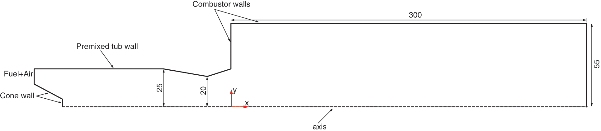
Figure 1: Schematic view of the computational domain (mm)
The origin coordinate system is taking place in the exit of the sudden expansion plan. The swirl generator has a wide range of blades angle that gives the swirl flow behavior. The cylindrical premixed duct with an inner diameter of D = 50 mm and a length of 156 mm. The converging-diverging nozzle has a throat diameter Dth = 40 mm. The combustor is a cylindrical tube with an inner diameter D = 110 mm and a length of 300 mm. The boundary conditions suitable for studying the lean premixed turbulent flame at different swirl numbers are as follows: the mass flow rate is imposed mmix = 46 g/s with the directional vector method is chosen to introduce the ratio between tangential and axial velocities (w/u) and 4.2% for the turbulence intensity with a hydraulic diameter of 0.01 m. The inlet temperature is 573 K, and the combustor walls are assumed adiabatic with no-slip boundary conditions. Axis-symmetric boundary condition is applied along with the numerical domain. At the outlet, pressure outlet boundary conditions with the backflow direction method normal to the boundary and the target mass flow option are applied to set the mass flow rate, and the temperature is about 1600 K. The interior domain is discretized with a refined non-uniform structured grid near the solution domain walls (Fig. 2).

Figure 2: Computational grid and near-wall view
The swirling reactive flow inside the combustor is governed by fluid mechanics equations combined with aero-thermochemistry. Two-dimensional forms predict the turbulent steady-state flow: the mass conservation, time-independent Reynolds averaged Navier-Stokes equations, and additional conservation equations, such as energy and species concentrations [12].
where, ρ is the mixture density (kg/m3), τ is the Reynolds stress tensor (Pa), g is the gravitational acceleration (m/s2), h, keff and T are the specific enthalpy (kJ/kg), thermal conductivity (W/mK) and mixture temperature (K), respectively, hi is the specific enthalpy of species i (kj/kg), Ji is the diffusion flux of the species i in the j direction (kg/m2s), N total number gas species, Sh and Srad are respectively the sources of energy caused by chemical reaction (kw/m3), the source of radiation obtained from the radiation model equations, Yi is the mass fraction of species i and Ri is the net rate of production of species i by chemical reaction (kg/m3s).
The most established turbulence model Standard k-ε was used for turbulent closure. It gives acceptable results in a short computational time than LES [13] and a suitable eddy-viscosity turbulence model for such flows. Furthermore, it has been extensively validated by engineering and academic applications. It is based on two transport equations: one for the turbulence kinetic energy (k) and the second for the dissipation rate of turbulence kinetic energy (ε). It can be written in tensor notations as follows [14]:
- Turbulence kinetic energy equation
- Dissipation rate equation
The eddy viscosity expression is obtained from k and ε combination as follows:
where, the model constants values are Cε1 = 1.44, Cε2 = 1.92, Cμ = 0.09 and σε = 1.3 as reported in [15].
The FR/EDM was selected for its key role in addressing the turbulent premixed flame’s turbulent-chemistry complex interaction. It computes both mixing rate and Arrhenius rate and takes the smaller of these two rates [16]. Only one or two-step reaction mechanisms can be used for more realistic results. A reduced chemical reaction mechanism for propane-air combustion consists 5 species and three reactions [17] was adopted in this study due to its low-cost computational effort. The P − 1 radiation model is chosen to better predict the temperature distribution inside the combustion chamber (C.C). Zeldovich’s mechanism, which contains three reversible reactions, was chosen based on fluent defaults to analyze the thermal NOx emissions formation [18]. The partial equilibrium approach is taken into account to compute the concentration O and OH radicals.
The swirling flow aims to achieve a stable flame and ensure good mixing of fuel-air stream, which subsequently affects the pollutant emissions. The swirl velocity is introduced by the ratio between tangential and axial velocities (w/u) at the inlet boundary conditions to give the flow the desired swirl velocity (tangential component). It is represented by the non-dimensional number (Sn), and its expression depends on the injector geometry, and flow profiles are written as follows [19]:
where, Rn and Rh denote the nozzle supporting blades and external swirl generator body radius, respectively.
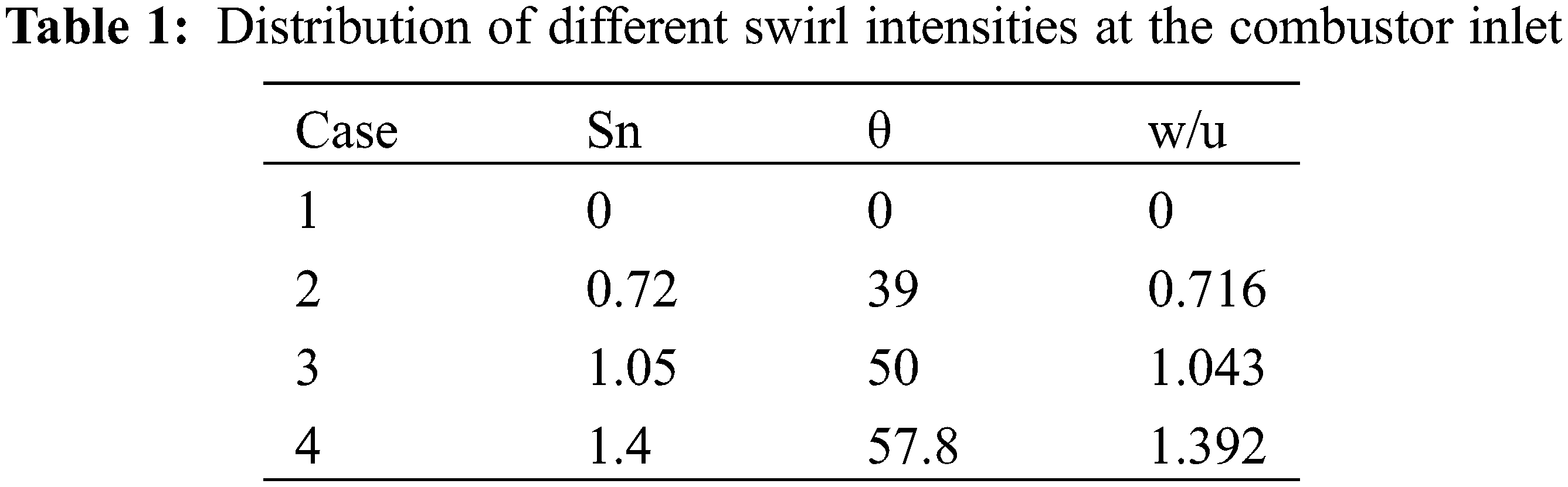
The effect of the Sn on combustion characteristics such as temperature, velocity, and outlet gas concentrations in a lean premixed propane flame was studied numerically using ANSYS-Fluent code, which uses a finite volume method and SIMPLE algorithm to solve the steady-state Navier-Stokes equations. The swirl numbers selected are equal to 0 (without swirl), 0.72, 1.05 (validation case), and 1.4 corresponding to the blade angle 0°, 39°, 50°, 57.8° (Table 1). We can note the weak effect of Sn and the critical value where the disturbance accrued in the flow structure creates an inner recirculation zone (IRZ) that appears at the C.C centerline (Fig. 5).
The computational domain was discretized using Gambit software (Version 2.4.6) with structured, no uniform cell grid finer in zones with important gradient temperature, velocity, and pollutant emissions. This provides adequate resolution near the expansion and the wall (Fig. 2) and close to the combustor exit. Therefore, the mesh effect was tested using three grid sizes (Table 2). The mean axial velocity at Sn = 1.05 and ϕ = 0.5 was selected as an illustrative example of computation results (Fig. 3).
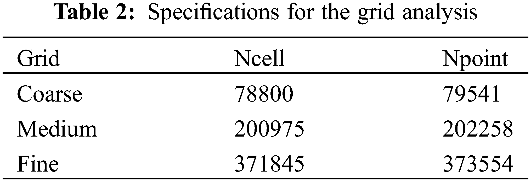
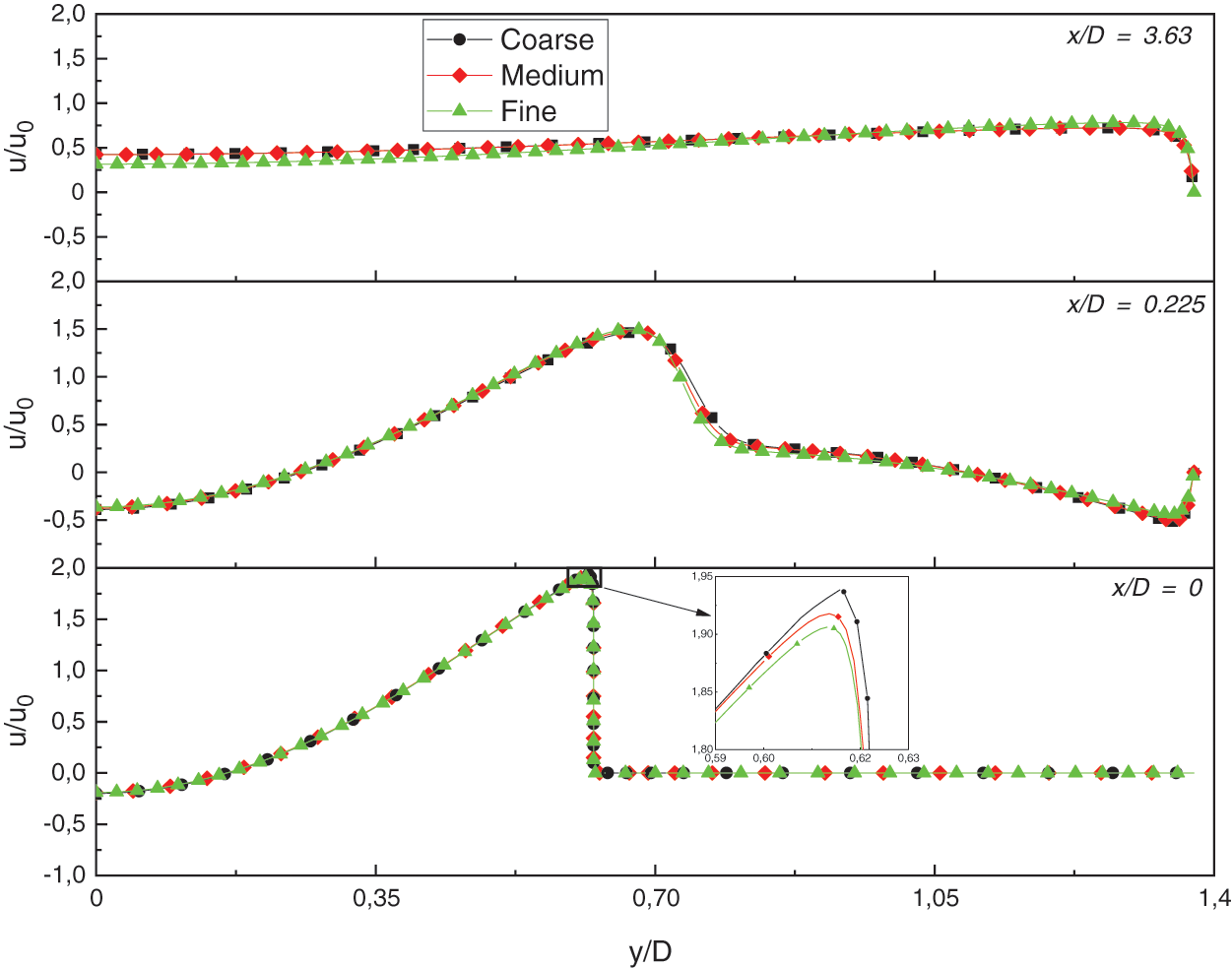
Figure 3: Mean axial velocity at different positions along the combustor for different mesh densities
This figure presents a comparison between radial profiles of the mean axial velocity at several locations along with the combustion chamber for the Coarse, Medium, and Fine mesh. Indeed, the coarse mesh at x/D = 0 is evident overestimates the velocity peak near y/D = 0.62 as shown in the zoom area. Furthermore, at x/D = 0.225, all mesh considered underestimates the axial velocity near the combustor wall, y/D = 1.365 due to the limited capability of Standard k-ε near the wall and x/D = 3.63 at around y/D = 0.35. It is observed that the mean axial velocity profiles predicted by the medium mesh with 202258 nodes are closer to the finer grid with 373554 nodes in comparison with the coarse grid and do not change considerably at each position chosen. Since the medium mesh (202258 nodes) gives reliable predictions in the cheapest computation time, it was adopted for all the calculations reported in this work.
4.2 Comparison of the Experimental Data with Eddy Viscosity Model
4.2.1 Axial and Radial Mean Velocity Profiles
Fig. 4 shows a comparison between the present numerical results with LDA measurements obtained by [5] concerning the mean axial (a) and mean radial velocities (b) profile for case 3 (Sn = 1.05 and equivalence ratio of 0.5) at three axial positions (x/D = 0, 0.225 and 1.127) throughout the combustion chamber. The standard k-ε turbulence model proves its capability to predict the formation of the ORZ and the IRZ with good accuracy compared to measurements data in such helicoidal flows of the premixed combustor (Fig. 6). Furthermore, Fig. 4a shows that at x/D = 0, the predicted axial velocity peak is u/u0 = 1.93 at around y/D = 0.618, which is quite higher than the measured axial velocity peak (u/u0 = 1.43).
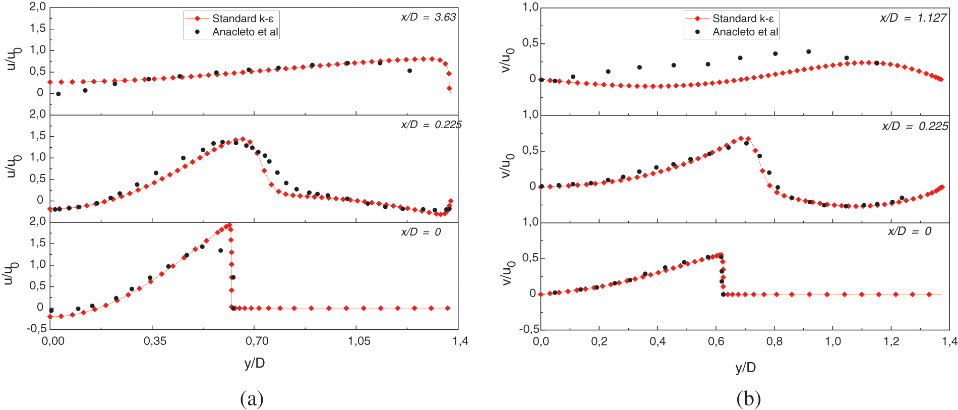
Figure 4: Comparison of predicted radial profiles of the axial (a) And radial (b) Mean velocities with Sn = 1.05 and ϕ = 0.5 at different axial positions with LDA data from [5]
In contrast, at x/D = 0.225 and x/D = 3.63, the velocity profiles have the same tendency, and the predicted profile gives a satisfactory prediction of the axial velocity value versus the measurements data. Fig. 4b shows that at x/D = 0 and x/D = 0.225, the standard k-ε model produces satisfactory predictions and give the same radial velocity peaks as the measurements, where v/u0 = 0.55 and 0.68, respectively. At x/D = 1.127 and near the centerline, the predicted profile describes the exact values of measurements, and far the centerline y/D > 0.23 and y/D < 0.85 is slightly overestimated the velocity profile, which is not expected. The Standard k-ε is a good turbulence model for simulating the swirling flows and is consistent with literature findings.
Fig. 5 presents the normalized profile of the flame temperature predicted by standard k-ε model and compared with the measured data as reported in [5] at three cross-sections (x/D = 0, 0.5 and 1.5) along with the combustion chamber, for Case 3 (Sn = 1.05 and ϕ = 0.5). The typical mean temperature within the combustion chamber is T0 = 1600 K. At x/D = 0.25. The Standard k-ε predicted poorly the temperature profile at around y/D < 0.72 due to the unsteady flow nature that involved a huge disturbance occurred at the same time near the expansion zone (i.e., shear zone, stagnation points). In addition, the high Sn (= 1.05) and fast chemical reaction significantly affect the flow behavior required to be solved with an advanced turbulence model. Meanwhile, the upper part, where y/D > 0.74, gives a good agreement with experimental data.
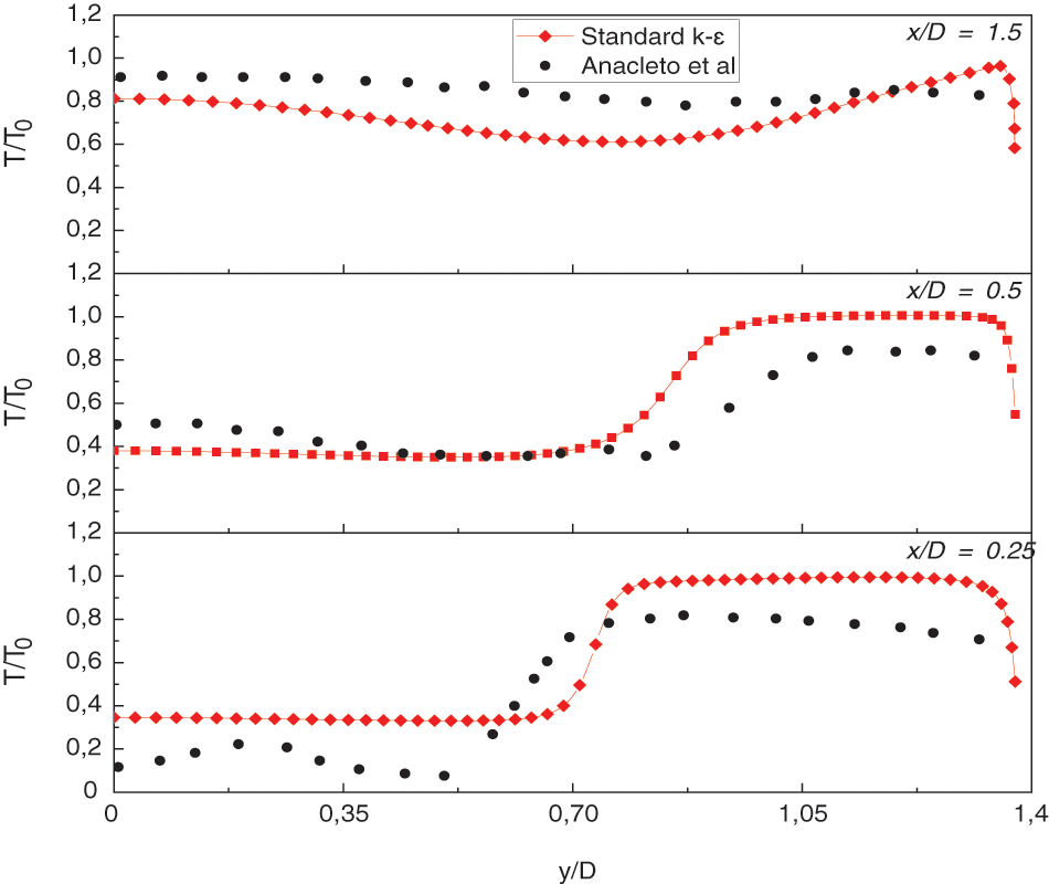
Figure 5: The radial temperature profile with Sn = 1.05 and ϕ = 0.5 at various locations along the combustor
However, at x/D = 0.5 and y/D < 0.18, the predicted model slightly overestimated the normalized temperature profile, whereas, at y/D > 0.18 and y/D > 1, it makes the same trend of the measured profile. Furthermore, at x/D = 1.5, a relatively flat normalized temperature profile was observed and remains unchanged, which indicates that the flow is hydrodynamically developed (∂u/∂x = 0 and dP/dx = cte) and reaches the fully developed region as presented in Fig. 4a at x/D = 3.63 and in Fig. 6. Thus, there is not much propane left to burn in this region. Again, the Standard k-ε proves its capability to capture the mean temperature field and gives satisfactory results.
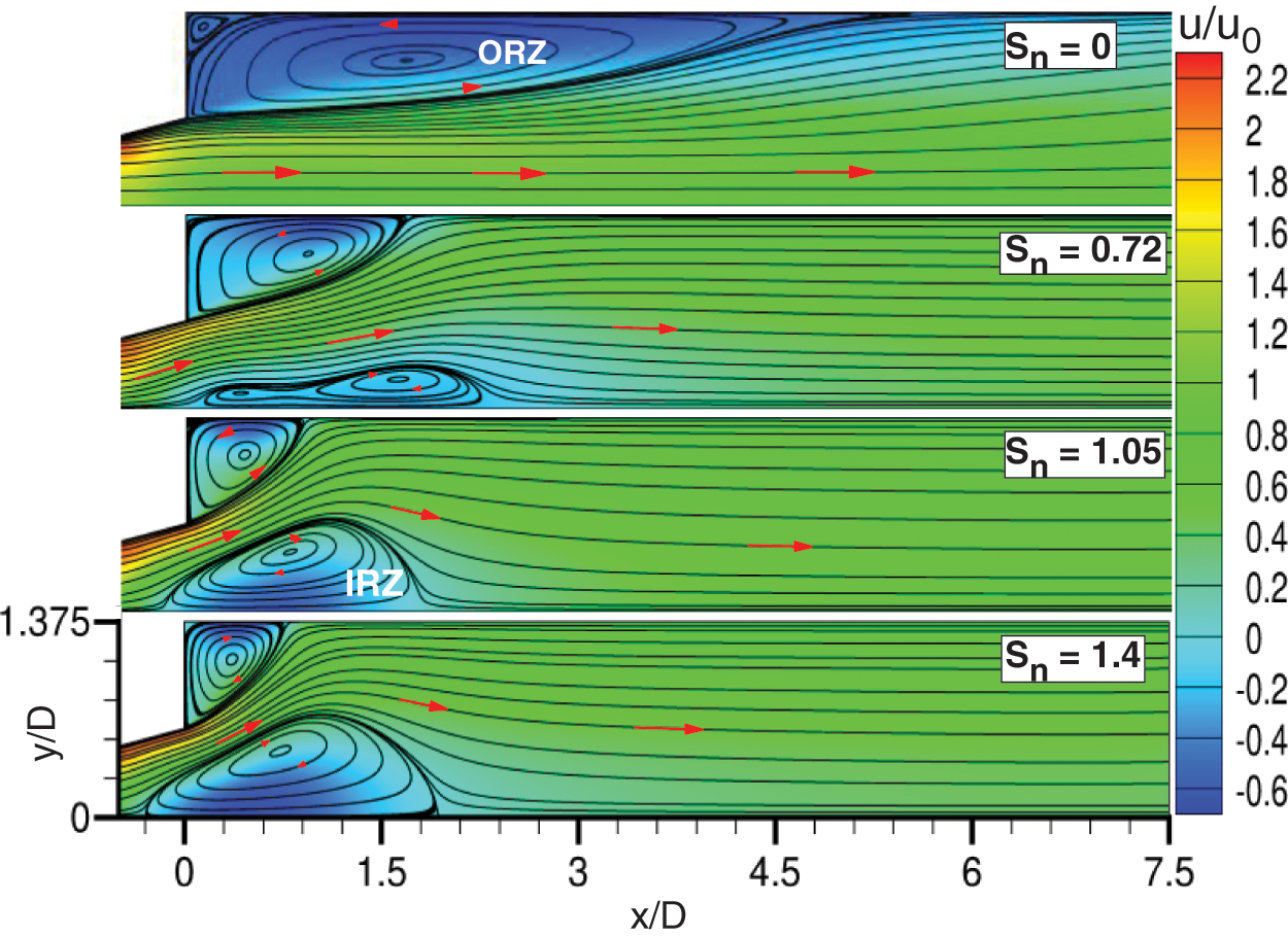
Figure 6: Streamlines and mean axial velocity contour with Sn = 0, 0.72, 1.05, and 1.4
4.3 The Effect of the Sn on the Flow Structure
Fig. 6 illustrates the streamlines and the mean axial velocity contours inside the combustion chamber for the four cases studied (Sn = 0, 0.72, 1.05, and 1.4). The legend selects minimum and maximum velocities corresponding to the minimum and maximum velocities encountered in the simulated cases. The mean axial velocity field and the streamlines allow visualizing the important zones and their evolution near the premixing tube, and at the inlet of the C.C. The swirl intensity strongly influences the flow structure. Thus, the presence of two recirculation zones, the first, an outer recirculation zone (ORZ), formed near the corners of the combustor independently of the Sn (= 0), where it rotates in a counter-clockwise direction.
The second is an inner recirculation zone (IRZ) that rotates clockwise and forms at the combustor centerline (xx). The Sn values control its intensity and axial position. For example, at Sn = 0, it is evident that the streamlines throughout the combustor are approximately parallel to the centerline axis (xx), and the ORZ covers a large area of 220 mm in length. Then by increasing the Sn to 0.72, the streamlines tend to take the radial direction (as represented by the red arrows), which reduces the size and the length of the ORZ to 70 mm, representing a reduction of 1/3 of ORZ length.
As a result, an IRZ appears at the center of the combustor inlet, and its length is 89 mm. Increasing the Sn to1.05, the length of ORZ decreases further to 38 mm, and the size of IRZ increases to reach 80 mm in length and 28 mm in width. In addition, the IRZ was created due to the decrease in axial velocity with the increase in tangential velocity as Sn increased. Moreover, at high Sn (= 1.4), the length of the ORZ keep decreases to 30 mm, and the size of IRZ becomes greater compared to other cases, which reach 90.2 mm in length and 30 mm in width, which represents an increase of 10.2 and 2 mm, respectively.
Moreover, it is moved toward the premixing tube, which leads to a flame flashback (Fig. 7). The radial profile of the mean axial velocity plotted at x/D = 0.07 shows the evolution of the IRZ during the increases of the Sn. Additionally, near the combustor centerline, the axial velocity reached its maximum value, u/u0 = 0.92 at Sn = 0 (IRZ does not exist). It decreases with the increases of Sn to reach a maximum negative value of |0.50|. This result indicates that the axial position of the IRZ moved gradually in the opposite direction of the jet stream with an increase of Sn. It can be noted that the IRZ is involved in the flame stabilization process and allows the contact of hot burned gases with fresh gases, which enhances the ignition process.
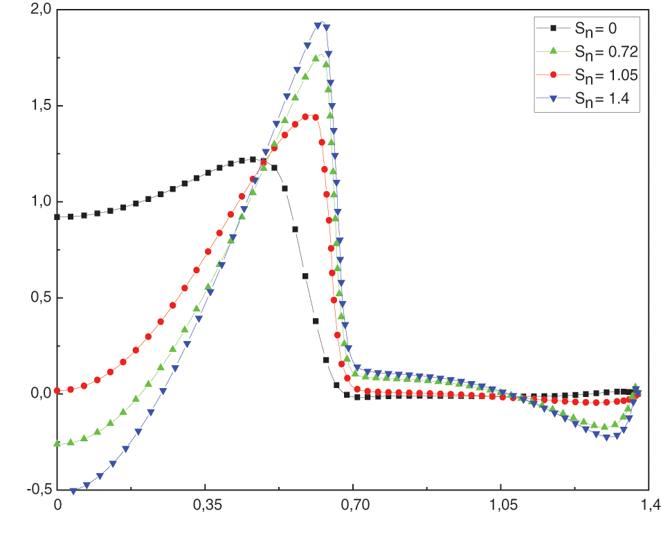
Figure 7: Radial profile of the mean axial velocity with Sn = 0, 0.72, 1.05, and 1.4 at x/D = 0.07
4.4 The Effect of the Sn on the Flame
Fig. 8 shows the effect of different swirl numbers (0, 0.72, 1.05, and 1.4) at ϕ = 0.5 on the spatial distribution of the mean gas temperature inside the C.C. The increase of the Sn reduces the flame length and controls its temperature. At Sn = 0, the temperature gradient does not change along the centerline (xx). The majority of the gases prevalent in this region are fresh gas due to the absence of the flow recirculation zone. It takes the lowest value (0.36 T0). Thus the flame is long and located along the combustor, and its temperature is about 0.937 T0 near the ORZ.
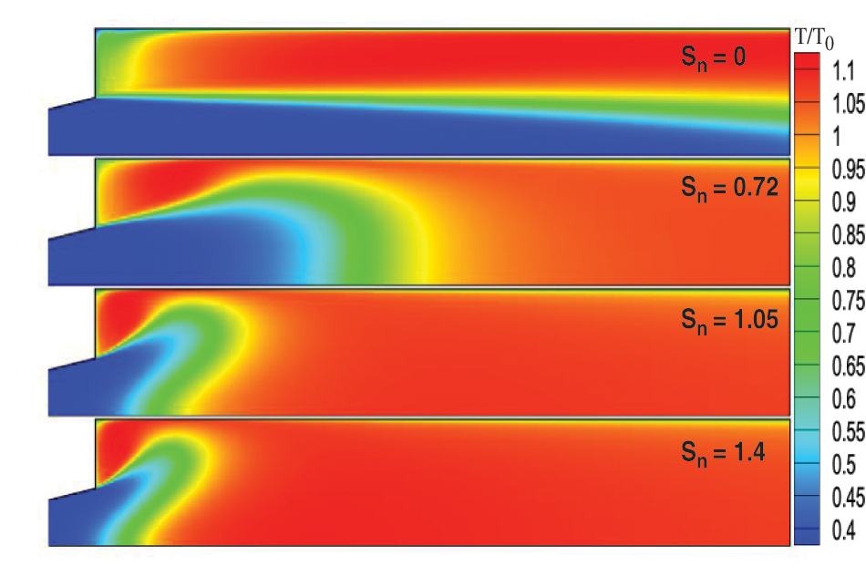
Figure 8: Spatial distribution of the temperature along the combustor with Sn = 0, 0.72, 1.05 and 1.4, at ϕ = 0.5
Meanwhile, combustion starts a little late in the transient state where Sn = 0.72. The flame shape tends to take O-form due to the tangential velocity application that changed the flow behavior discussed in Section 2.3 and the vortex pattern created in the flame. This result indicates that the flow behavior significantly influences the flame shape. In addition, the maximum temperature is obtained in this case, and its value is 1.109 T0 at the ORZ. The reaction zone’s length is reduced when the Sn increases (Fig. 9).
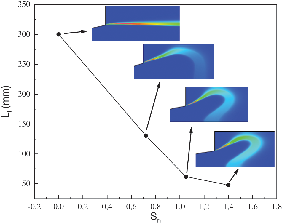
Figure 9: Flame length with Sn = 0, 0.72, 1.05, and 1.4, at ϕ = 0.5
In addition, increasing the Sn to1.05 leads the flame to take M-form and move smoothly toward the premixing tube, where its temperature decreases to 1.104 T0. This is due to the development of the IRZ that reaches approximately its maximum size maximizes the mixing between the air and fuel (C3H8-air). Consequently, the thermal NOx emissions will be reduced (Fig. 10). Moreover, this case is the most stable case where the premixed flame operates in optimum condition and remains stable.
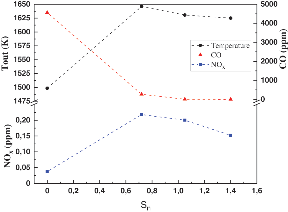
Figure 10: Temperature with CO and NOx profiles as a function of swirl numbers at the combustor exit
However, by further increasing the number of swirls up to Sn = 1.4, the temperature decreases until it reaches the lower value of 1.091 T0 due to the uniform distribution of the flame temperature along the C.C, eliminating the high-temperature points in the flame front. Also, the flame position keeps approaching the premixing tube, which means the decreases in the axial velocity of the flow that leads to a flame flashback and increases the residence time of the combustion products inside the C.C [20].
Fig. 9 presents the flame length and shape as a function of the Sn at ϕ = 0.5. The flame length is identified using the maximum height of the C3H8 reaction rate within the combustor. The change in the Sn did not show any tendency of the flame lift-off even at a higher intensity. Thus, it significantly affects the flame shape and its length. However, in the non-swirling state (Sn = 0), the flame is anchored along the combustor, where its length reaches a maximum value of 300 mm.
Meanwhile, at the transient state (Sn = 0.72), the flame remains attached to the ends of the contraction, and its length reduces by 56.5% to reach 130.5 mm. This is because the flow is spread in the radial direction, which inspires the flame near the premixing tube. By increasing the Sn to 1.05, the propane flame holds in the IRZ, where it takes the M-form and becomes quite thinner and more stable than others. In addition, the flame length is reduced further to reach 62 mm, which represents a reduction of 79.33%. Moreover, increasing the Sn reduces the reaction time of major species like Oxygen and Nitrogen in the reaction zone, which reduces the NOx formation rate. For a high Sn (= 1.4), the flame length is reduced by 84%, occurring at 48 mm from the contraction outlet. Thus, it becomes thickened and more intense. It is noteworthy that for Sn = 1.05 and 1.4, the flame front is in contact with the combustor walls.
4.5 Species Concentration Profiles
Fig. 10 illustrates the temperature and emissions of CO and NOx as a function of Sn (= 0, 0.72, 1.05, and 1.4) at the combustor exit. The change of the Sn from low to high intensity significantly affects the flame temperature. It results in the formation of CO and NOx pollutants emissions at the combustor exit. The higher CO emission concentration of 4562 ppm occurred at the non-swirl state (Sn = 0) due to the low outlet temperature (Tout) (1498 K) and low residence time. Thus, this low outlet temperature inhibits the oxidation process of CO. Furthermore, CO concentration decreases with the increase in Sn, where it reaches 266, 6.3, and 0.7 ppm at Sn = 0.72, 1.05, and 1.4, respectively. However, the decreases in CO concentration from 4562 to 0.7 ppm represent a decrease of around 99%. In addition, the CO converted to CO2 increases with increasing Sn due to the increase in outlet temperature.
Also, Fig. 10 shows the effect of the Sn on the outlet temperature and the thermal NOx concentrations. The formation of the thermal NOx emissions depends strongly on the flame temperature. For example, at Sn = 0, the NOx concentration is 0.038 ppm at low Tout, which is 1498 K. This very low NOx concentration occurs due to the poor mixing rate, no IRZ is found, and very low residence time. Meanwhile, the high NOx concentrations formed at Sn = 0.72 (Transition state) where its value reaches 0.22 ppm at Tout = 1646 K. Furthermore, increasing the Sn to 1.05, the fuel-air mixing rate enhanced, which results in a decrease in Tout, where its value is 1630 K. Since the NOx emissions are temperature-dependent, the concentration of NOx decreases to 0.20 ppm, which represent a reduction of 8.16%.
Moreover, keep increasing the Sn till 1.4 decreases the Tout to 1615 K, decreasing the NOx concentration to 0.16 ppm, representing a reduction of 30.15% compared to Case 2. This reduction could be explained by the fact that the increase in the Sn decreases the flame length, which shortens the reaction time in the flame zone between nitrogen and oxygen species. It can also be explained by the strong interaction of the turbulence-chemical, which leads to achieving complete vaporization and mixing between the reactants and unburned gases near the inner shear layer where the IRZ encountered the jet stream.
2D numerical simulations were conducted to evaluate the effect of swirl number (Sn) on combustion characteristics such as temperature, velocity, and outlet gas concentrations in a lean premixed propane flame. Four cases with four different swirl numbers (0, 0.72, 1.05, and 1.4) were analyzed. A numerical model was validated with existing experimental data of the stable case (Sn = 1.05 and ϕ = 0.5), and a good agreement with measurements is found. According to the numerical results, the change in the Sn significantly impacts the flow behavior, such as axial velocity and the size of the ORZ and IRZ. As a result, the temperature at the combustor exit and the outlet gas concentrations, including CO and NOx. The results show that at the lowest Sn (= 0), an ORZ was developed independently of it. The propane flame is located along the combustor. It has the lowest axial velocity, outlet temperature, and NOx concentration, 1.22 u0, 1498 K, and 0.037 ppm, respectively, against the higher CO concentrations of 4562 ppm.
Increasing Sn from 0 to 1.4, the size of the ORZ was reduced, revealing two flame types, O-form and M-form, in which its length decreases by 56.5%, 79.33% 84%, respectively. At the same time, an IRZ appears at the centerline due to vortex breakdown, which moves gradually toward the combustor inlet leading to a flame flashback at Sn = 1.4. The outlet temperature reaches a maximum value of 1646 K at Sn = 0.72 with a higher NOx concentration of 0.22 ppm. These high NOx emissions indicate the significance of the temperature in forming the CO and NOx emissions inside the combustor. In conclusion, the swirl technique application in turbulent premixed flame appears to be extremely promising for the flame dynamics and the formation of pollutant emissions, such as CO and NOx. The application of this technique with a good dilution strategy could improve the efficiency of the flame is currently under study.
Acknowledgement: The authors appreciate the assistance and the valuable advice given by Mr. Zakaria Mansouri.
Funding Statement: This work was supported by the University of Science and Technology Houari Boumediene (U.S.T.H.B.) and Energy Mechanics and Conversion Systems Laboratory.
Conflicts of Interest: The authors declare that they have no conflicts of interest to report regarding the present study.
1. Chuang, S., Yang, C., Wu, N. (1999). Predictions of swirling flow in sudden-expansion dump combustor with flameholder side-inlet using two-step combustion model. International Journal of Numerical Methods for Heat and Fluid Flow, 9(7), 764–787. DOI 10.1108/09615539910291154. [Google Scholar] [CrossRef]
2. Khanafer, K., Aithal, S. M. (2011). Fluid-dynamic and NOx computation in swirl burners. International Journal of Heat and Mass Transfer, 54(23–24), 5030–5038. DOI 10.1016/j.ijheatmasstransfer.2011.07.017. [Google Scholar] [CrossRef]
3. Elorf, A., Sarh, B., Tabet, F., Bostyn, S., Asbik, M. et al. (2019). Effect of swirl strength on the flow and combustion characteristics of pulverized biomass flames. Combustion Science and Technology, 191(4), 629–644. DOI 10.1080/00102202.2018.1497611. [Google Scholar] [CrossRef]
4. Yılmaz, İ. (2013). Effect of swirl number on combustion characteristics in a natural gas diffusion flame. Journal of Energy Resources Technology, 135(4), 1–8. DOI 10.1115/1.4024222. [Google Scholar] [CrossRef]
5. Anacleto, P. M., Fernandes, E. C., Heitor, M. V., Shtork, S. I. (2003). Swirl flow structure and flame characteristics in a model lean premixed combustor. Combustion Science and Technology, 175(8), 1369–1388. DOI 10.1080/00102200302354. [Google Scholar] [CrossRef]
6. İlbaş, M., Karyeyen, S., Yilmaz, İ. (2016). Effect of swirl number on combustion characteristics of hydrogen-containing fuels in a combustor. International Journal of Hydrogen Energy, 41(17), 7185–7191. DOI 10.1016/j.ijhydene.2015.12.107. [Google Scholar] [CrossRef]
7. Mansouri, Z., Aouissi, M., Boushaki, T. (2016). A numerical study of swirl effects on the flow and flame dynamics in a lean premixed combustor. International Journal of Heat and Technology, 34(2), 227–235. DOI 10.18280/ijht.340211. [Google Scholar] [CrossRef]
8. Huang, Y., Yang, V. (2005). Effect of swirl on combustion dynamics in a lean-premixed swirl-stabilized combustor. Proceedings of the Combustion Institute, 30(2), 1775–1782. DOI 10.1016/j.proci.2004.08.237. [Google Scholar] [CrossRef]
9. Stone, C., Menon, S. (2002). Swirl control of combustion instabilities in a gas turbine combustor. Proceedings of the Combustion Institute, 29(1), 155–160. DOI 10.1016/S1540-7489(02)80024-4. [Google Scholar] [CrossRef]
10. Datta, A., Som, S. K. (1999). Combustion and emission characteristics in a gas turbine combustor at different pressure and swirl conditions. Applied Thermal Engineering, 19(9), 949–967. DOI 10.1016/S1359-4311(98)00102-1. [Google Scholar] [CrossRef]
11. Duwig, C., Ducruix, S., Veynante, D. (2012). Studying the stabilization dynamics of swirling partially premixed flames by proper orthogonal decomposition. Journal of Engineering for Gas Turbines and Power, 134(10), 101501. DOI 10.1115/1.4007013. [Google Scholar] [CrossRef]
12. Alliche, M., Chikh, S. (2018). Study of non-premixed turbulent flame of hydrogen/air downstream co-current injector. International Journal of Hydrogen Energy, 43(6), 3577–3585. DOI 10.1016/j.ijhydene.2017.06.081. [Google Scholar] [CrossRef]
13. Li, Z., Kharoua, N., Redjem, H., Khezzar, L. (2012). Rans and LES simulation of a swirling flow in a combustion chamber with diffirent swirl intensities. ICHMT International Symposium on Advances in Computational Heat Transfer, pp. 1713–1728Begellhouse, Connecticut, Bath, England. DOI 10.1615/ICHMT.2012.CHT-12.1030. [Google Scholar] [CrossRef]
14. Saqr, K. M., Aly, H. S., Wahid, M. A., Sies, M. M. (2009). Numerical simulation of confined vortex flow using a modified k-ε turbulence model. CFD Letters, 1(2), 87–94. [Google Scholar]
15. Launder, B. E., Sharma, B. I. (1974). Application of the energy-dissipation model of turbulence to the calculation of flow near a spinning disc. Letters in Heat and Mass Transfer, 1(2), 131–137. DOI 10.1016/0094-4548(74)90150-7. [Google Scholar] [CrossRef]
16. ANSYS (2020). Academic Research Release 19.0, Help System. The Generalized Finite-Rate Formulation for Reaction Modeling, ANSYS Inc. [Google Scholar]
17. Westbrook, C. K., Dryer, F. L. (1981). Simplified reaction mechanisms for the oxidation of hydrocarbon fuels in flames. Combustion Science and Technology, 27(1–2), 31–43. DOI 10.1080/00102208108946970. [Google Scholar] [CrossRef]
18. Bowman, C. T. (1979). Kinetics of pollutant formation and destruction in combustion. Progress in Energy and Combustion Science, 1(1), 33–45. DOI 10.1016/0360-1285(75)90005-2. [Google Scholar] [CrossRef]
19. Gupta, A. K., Syred, N., Lilley, D. G. (1984). Swirl flows. Tunbridge Wells: Abacus House. [Google Scholar]
20. Amirjavad, A. K., Maryam, G., Mohammad, M., Seyed, H. P. (2020). Numerical study of inlet air swirl intensity effect of a methane-air diffusion flame on its combustion characteristics. Case Studies in Thermal Engineering, 18, 100610. DOI 10.1016/j.csite.2020.100610. [Google Scholar] [CrossRef]
 | This work is licensed under a Creative Commons Attribution 4.0 International License, which permits unrestricted use, distribution, and reproduction in any medium, provided the original work is properly cited. |