| Fluid Dynamics & Materials Processing |
DOI: 10.32604/fdmp.2023.018275
ARTICLE
A Numerical Investigation on the Influence of the Circular Ring on the Aerodynamic Noise Generated by a Cooling Fan
1State Key Laboratory of Precision Blasting, Jianghan University, Wuhan, 430056, China
2School of Intelligent Manufacturing, Jianghan University, Wuhan, 430056, China
3Key Laboratory of Optoelectronic Chemical Materials and Devices, Ministry of Education, School of Chemical and Environmental Engineering, Jianghan University, Wuhan, 430056, China
4Institute for Interdisciplinary Research, Jianghan University, Wuhan, 430056, China
5Guangdong HUST Industrial Technology Research Institute, Dongguan, 523429, China
*Corresponding Author: Bing Wang. Email: wangbing@jhun.edu.cn
Received: 12 July 2021; Accepted: 23 May 2022
Abstract: The influence of the width of the circular ring of a car cooling fan on the aerodynamic noise is investigated numerically through the determination of the overall sound pressure level (OASPL). The results demonstrate that when the circular rings cover near 2/3 of the width of the blade tips of the rotor in the axis direction, the rotor has the lowest OASPL and the related total pressure efficiency and flow mass rate are better than the corresponding values obtained for a reference rotor without a circular ring. With increasing the width of the circular ring in the axis direction, the tip vortex around the trailing edge of the blade tip becomes smaller and finally disappears. Meanwhile, a separated flow field arises gradually and then grows in size around the middle of the junction of the blade tips with the ring. When the circular rings cover nearly 2/3 s of the width of the blade tips of the fan in the axis direction, the extension of the separated flow around the blade ’s tip attains a minimum.
Keywords: Cooling fan; width of the circular ring; aerodynamic noise; CFD simulation
Nomenclature
| U | Flow velocity |
| rpm | Round per minute |
| ρ | Density of fluid |
| μ | Dynamic viscosity |
| Re | Reynolds number |
| | Means velocity of the flow |
| | Fluctuating velocity of the flow |
| p | Pressure |
| Q | Mass rate of the flow |
| | Difference between the total pressure of the downstream and upstream of the rotor |
| M | Torque of the rotor |
| n | Rotational speed of the rotor |
| | Subgrid-scale stress |
| | Mesh size along the i-axis |
In recent years, noise pollution has become an important part of environmental pollution. As a part of the engine cooling system, the cooling fan is one of the noise sources in automobiles. As the environmental protection standards become more and more stringent, the automobiles must be equipped with more devices such as exhaust gas purification systems, which lead to increased temperature in the engine hood, increased load, and thus increased noise. With the development all around the world, the market for electric automobiles has grown. The electric automobile does not have loud noise from the engine as the background noise so the human ears become more sensitive to the noise from the other components. Therefore, reducing the noise caused by the cooling fans or the other fans, such as the fans of the air conditioner, makes a lot of sense. Noise is produced by the sound generator when it vibrates irregularly, which is a kind of energy loss. When the noise is reduced, the energy is saved, and the efficiency is also improved. With this understood, the research on the aerodynamic performance and the noise caused by the cooling fans is of great significance to the development of the automobile industry. The aerodynamic noise, as one of the main causes of the noise, is generated by the interaction between the air and the rotating fan. In order to reduce the aerodynamic noise, the methods are widely used by improving the structure, the impeller shape, the blade shape, and the material of the cooling fans. Meanwhile, the air volume and efficiency must be maintained. Many researchers [1–8] have studied the flow mechanism of aerodynamic noise to reduce the noise caused by the fans.
Sun [9] deduced the sound radiation formula of the unequal spaced fan according to the BLH (Blade Loading Harmonics) theory and obtained that the unequal spaced blade distribution can effectively reduce fan noise by their experiments.
Han et al. [10] tried to find the static pressure distribution with the least energy loss by measuring the static pressure distribution on the end wall and the blade surface of different cascades at different air attack angles and blade installation angles.
Moreau et al. [11–13] tried to use the CFD method to develop and design a fan, which not only improved the comprehensive performance of the fan, but also greatly shortened the product design cycle greatly, therefore reducing the product development cost. In order to obtain a better internal flow field, they also proposed a new fan CFD model and used a new meshing method to study the situation of both stationary and moving blades.
Kohri et al. [14,15] used the visualization method and the CFD simulation model to study the performance of the cooling fan in a small truck and successfully solved the practical problems. Then they studied the influence of the multiple reference system methods on the performance prediction of the engine cooling fan.
Oh et al. [16] used Ansys Fluent to study the fan performance parameters of a four-blades propeller fan at a low flow mass rate, and compared the simulations with the experiment results. The results showed that the deviation between the simulation and the experiment was within the permissive range. The effectiveness of CFD numerical simulation is, in this instance, proven.
Morris et al. [17] applied a new type of aerodynamic hood to the axial-flow cooling fan. The experiment showed that the performance of the noise and efficiency of the fan were improved at both the medium and large flow rates, but decreased at a lesser flow rate.
Zhao et al. [18] selected seven of the influence factors of the fan, such as the number of blades, hub ratio, installation angle, blade angle, etc. The influence of fan performance were numerically investigated, and the influence characters of the seven factors were then summarized.
Jang et al. [19] studied the ear-type housing and a newly designed housing in order to control the blade tip vortex of the axial flow fan of the air-conditioning. The newly designed housing reduces the obstruction to the main flow and increases the flow rate. At the same time, the noise is reduced by 1.5 dB (A).
Nashimoto et al. [20,21] and Ota et al. [22] studied the influence of the tip winglets on the blade of the open fan and the annular fan evolved from it on the vortex intensity at the blade tip, which could increase the static efficient and reduce the aerodynamic noise.
Tang et al. [23] concluded that the annular fan can avoid the eddy current back-flow loss of the open fan at the outer end of the blade, reduce the discontinuous air friction and impact loss at the outer end of the open fan blade, and reduce the aerodynamic noise while improving the fan efficiency and increasing the air volume.
Mo et al. [24,25] studied the effect of the structure and parameters of engine annular cooling fans on the aerodynamic performances.
Recently, the research group of Bian et al. [26–28] tried to study the flow loss and flow structure of the blade by numerical and experimental investigations and tried to investigate the influence of the splitter geometry on the secondary flow control.
From the studies above, the methods have been used to improve the aerodynamic performances and the aerodynamic noise generated by way of improving the structure, impeller shape, blade shape, and material of engine cooling fans. But the noise reduction method for the engine circular cooling fans is rarely reported.
In this study, the influence of the widths of the circular ring of a car cooling fan on the aerodynamic noise is investigated by numerical method. The primary purposes of this study are:
(1) Detecting the influence of the widths of the circular ring of a car cooling fan. Changing the widths of the circular ring could control the separated flow around the blade tips, and this method have the potential ability to reduce the aerodynamic noise generated by the fan.
(2) Detecting the flow structure around the blades of the fan to discover the influence of the widths of the circular ring on the separated flow around the blade tips.
In this study, four models of the fans are chosen to investigate the influence of the widths of the circular ring of a car cooling fan on the aerodynamic noise. The model of the original fan has no circular ring named Rotor A, as shown in Fig. 1. It has nine blades with a diameter of 490 mm. On the basis of the original fan, the other three fans are designed with circular rings, as shown in Fig. 2. The fans are named from Rotor B to Rotor D. They have different circular-ring-widths. The radial thicknesses of the circular rings are all 6 mm. The axial widths of the three circular rings are respectively 18.3, 36.7, and 54.0 mm, from Rotor B to Rotor D as shown in Fig. 3. When the width of the circular ring is 54 mm, the circular ring just covers the tip of the blades in the axial direction.
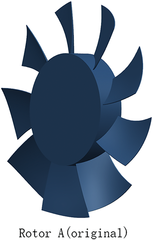
Figure 1: Original fan
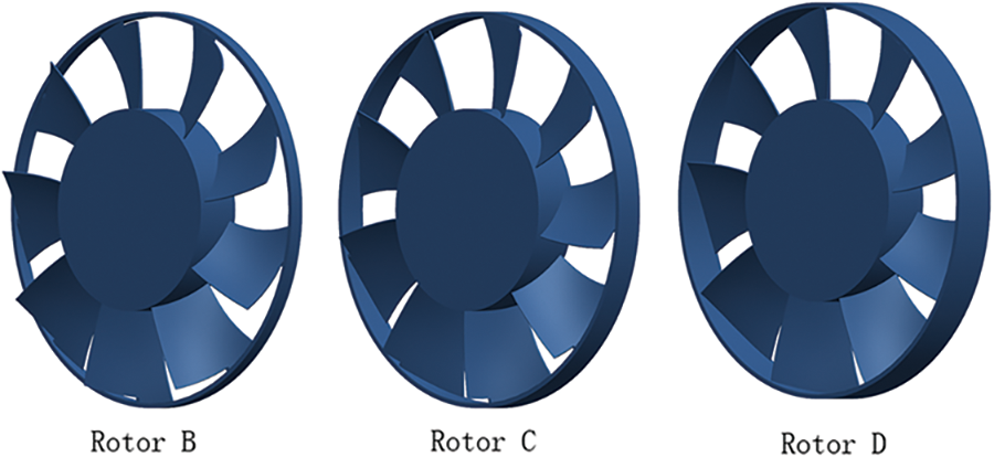
Figure 2: Fans with circular rings
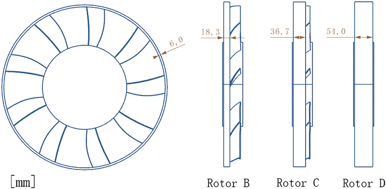
Figure 3: Diagrams of three fans with circular rings
The numerical simulation field boundary is shown in Fig. 4. The distance between the inlet and the fan is 1000 mm and the distance between the fan and the outlet is 1500 mm. The wall surface of the pipe is set to a no-slip wall, and the gap between the fan and the pipe surface is 17 mm. The origin of the coordinate is the center of the fan, and the x-axis is the flow direction from the upstream to the downstream of the flow as shown in Fig. 4.
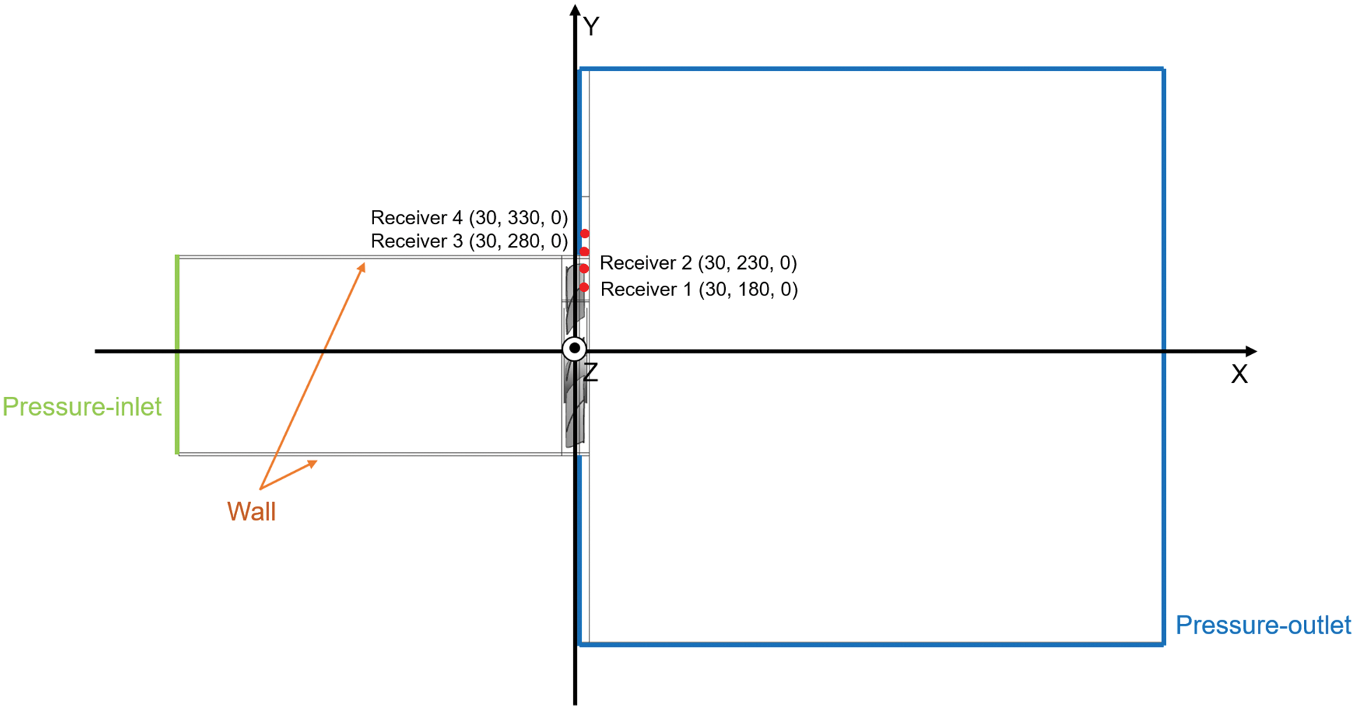
Figure 4: Simulation field of the flow domain and noise monitoring point distribution
The rotational speed of the fans is set to 3000 r/min, and the fan mesh is a no-slip mesh for steady flow and a slip mesh for unsteady flow to simulate the rotation. The part of the rotor mesh is set as the rotating part. The other parts of the mesh are set as stationary parts.
The analysis of the aeroacoustics in this study is conducted based on the Ffowcs-Williams & Hawkings (FW-H) model [29,30] of the LES large eddy simulation method. FW-H is chosen as the model of noise analysis. The positions of the noise receivers are also shown in Fig. 4. The rotors are chosen to be the noise sources when the FW-H equation is applied to calculate the noise at the receivers.
The CFD simulation mesh is generated by using the software ICEM CFD. Three-dimensional hybrid grids are created for the blades. The fan is set to an unstructured grid and the other areas are block-structured grids. The total grids consist of about 6 million cells. The CFD simulations are conducted by ANSYS Fluent, including the steady and unsteady simulations. The steady-state is used as an initial condition for the unsteady simulations.
The assumptions of isothermal (i.e., μ = const.), so the energy equation is not necessary, and no boundary condition for the temperature is set. Then the gravity term is not considered. The first-order upwind scheme is used to represent the convection terms of the governing equations. The semi-implicit method for pressure-linked equation (SIMPLE) [31] is used to solve the discretized equations. The velocity of inflow is smaller than Mach number 0.3, so the flow is considered as incompressible (ρ is consistent). The turbulent intensity is set as 2%, which is tested in the wind tunnel in our lab [27,28]. The turbulent length is set as 0.0367 m [28].
As for the steady simulation, Reynolds-Averaged Navier-Stokes equations (RANS) are solved on the grids. The RANS equations for a stationary, incompressible Newtonian fluid are summarized in tensor notation as:
In the steady CFD simulations, the transition SST (shear stress transport for short) [32] is chosen as the turbulence model as:
where y is the distance nearest to the wall.
In order to obtain the fluctuating pressure in the flow, unsteady CFD simulations are needed. In the unsteady CFD simulations, the LES is chosen as the turbulence model. The Smagorinsky-Lilly model of the LES (large eddy simulation) is chosen as the turbulence model. The equations for a rotational, incompressible Newtonian fluid are summarized in tensor notation as [33]:
where G(x, x’) is the filter function and Cs = 0.7.
According to the recommendation of the ANSYS Fluent 15.0 [34], the maximum y+ should be smaller than 1 for the turbulence model chosen in this study, so the maximum height of the first layer of the cells from the walls is set as 0.005 mm. In this study, ICEM CFD is used to create the three-dimensional grid, as shown in Fig. 5a. The fan is set to an unstructured grid, and the other areas are structural grids. In order to ensure high mesh quality and improve calculation accuracy, the mesh in the vicinity of the wall boundary layer is refined, as shown in Fig. 5b. For the unsteady CFD simulations, the time step size is set to 2.5 × 10⁻⁴ s, and the number of the time steps is set to 2000. The aerodynamic noise analysis is based on the last 1000 time steps, which is according to the method of the research team from Jilin University [35].
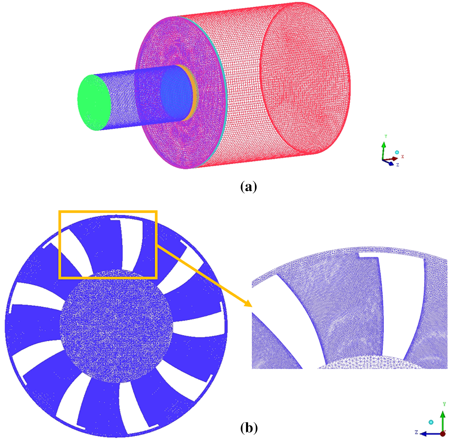
Figure 5: Grids of the simulation (a) Overall grids and (b) Grids detail near the wall
The grid independence test is conducted for the original fan, as shown in Fig. 1. The cell numbers of the grids are changed near the blades to check whether the grid resolution is sufficient for the simulation work. The simulation grid of the original fan used in the study has about 6 million cells, which is named grid 1 in Table 1. From grid 2 to grid 5 in Table 1, the cell numbers are about 4.6 million, 6.4 million, 7.7 million, and 16.4 million, respectively. The result of the grid independence test is shown in Table 1. The number of the time steps of the unsteady simulating is set to 256 especially, and the aerodynamic noise analysis is based on the last 128 time steps, which is just conducted in this part. It is indicated that the cell number of the girds has no significant effect on the simulation results.

4.1 Blade Suction Surface Static Pressure Distribution
The blade suction surface static pressure distributions of the four fans with different widths of the circular rings are shown in Fig. 6. Of the fans, the separation field on the tip of the blades of Rotor C is the smallest. The width of the circular ring of Rotor C is nearly 2/3 of that of Rotor D, whose circular ring just covers the tip of the blades in the axial direction. These separation fields are caused by the local separation of the flow around the blade tips, where the tip vortex occurs [4]. From Fig. 6, it is indicated that the separated fields around the blade tip become smaller firstly and then more oversized with the width of the circular ring increasing in the axis direction. Moreover, from Rotor A to Rotor C, with the width of the circular ring increasing, the separated fields around the trailing edges of the blade tips become smaller and even disappear at times. Meanwhile, from Rotor C to Rotor D, the lower pressure field arises gradually and becomes bigger around the middle of the junction of the blade tips and the circular ring. It means that the flow is separated around the middle of the junction of the blade tips and the circular rings. The wall of the circular rings also causes pressure losses and flow separations at last. In a word, with the widths of the circular rings increasing in the axis direction, the tip vortices around the trailing edge of blade tips become smaller and disappear at last. Meanwhile, the separated flow fields arise gradually and become bigger around the middle of the junction of the blade tips and the circular rings. When the circular rings cover nearly 2/3 s of the width of the blade tips of the fan in the axis direction, the separated fields of the flow around the blade tips of the fans are the smallest.
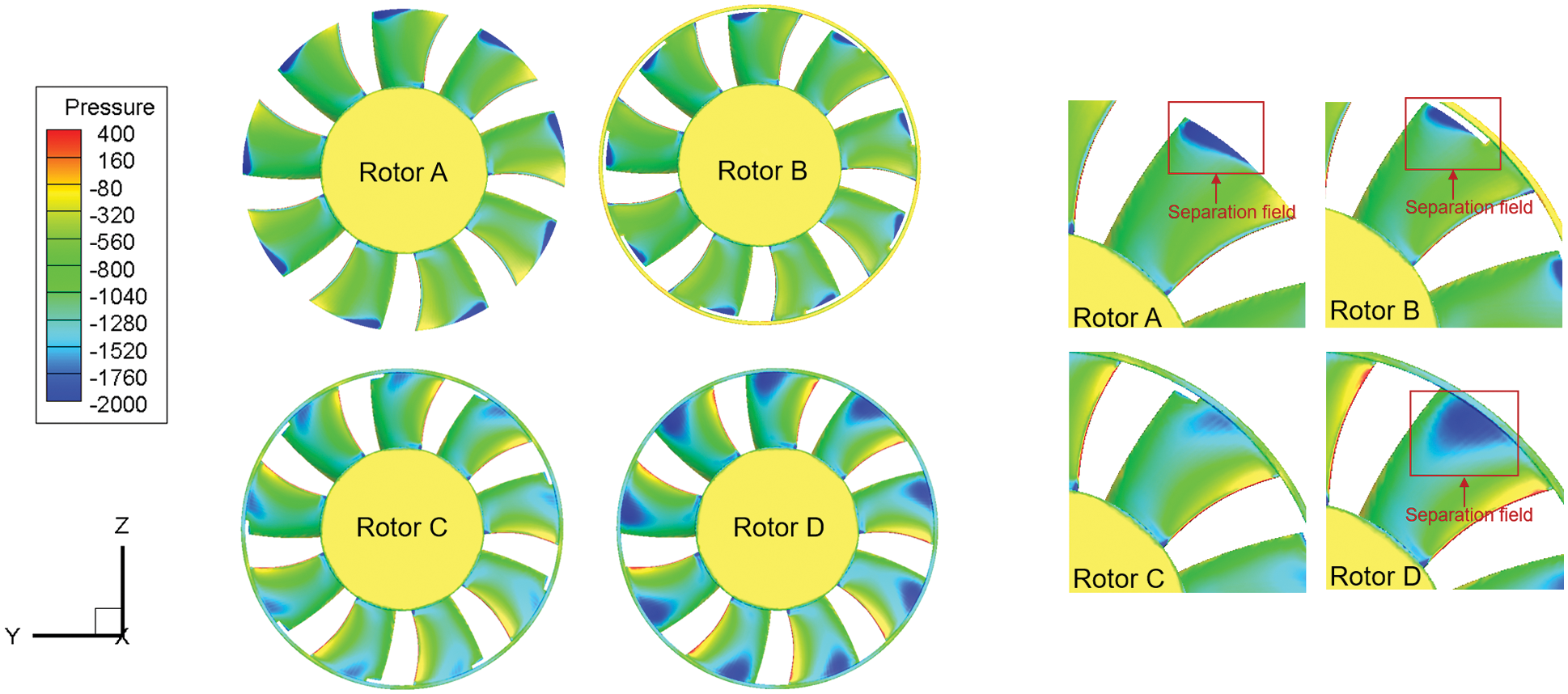
Figure 6: The blade suction static surface pressure distribution of the rotors
The streamlines of the flow around the four fans are shown in Fig. 7. It is indicated that the streamlines of the flow are parallel to the wall upstream of the fans.
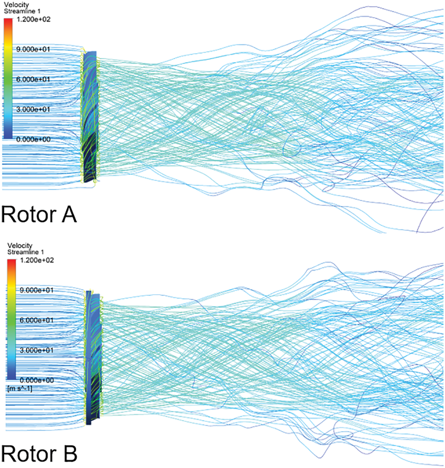
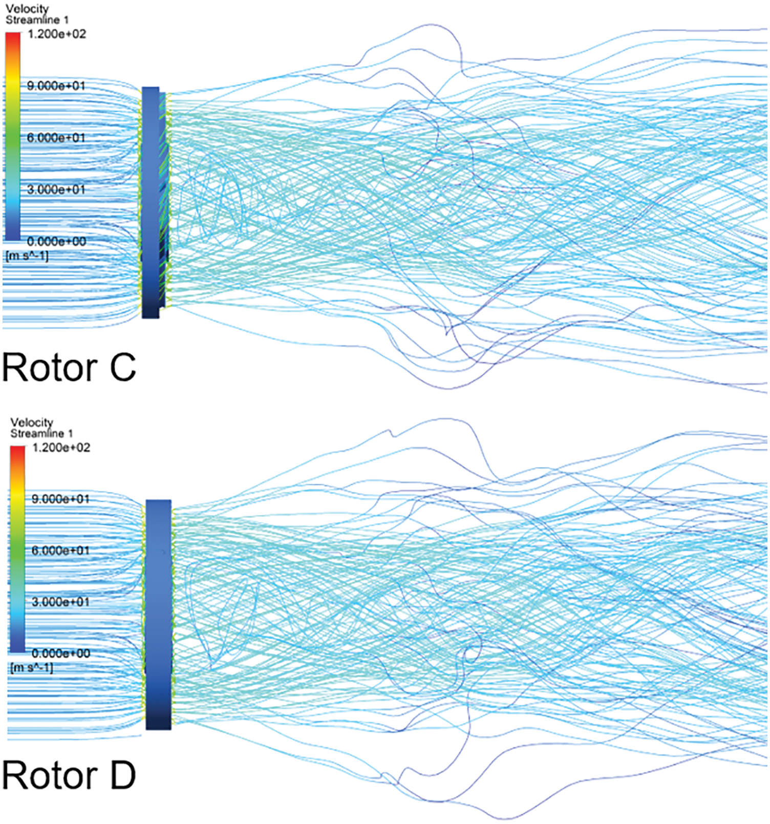
Figure 7: The streamline of the fans
Meanwhile, the streamlines of the flow are sped up and become rotary because of the rotational motion of the fans upstream. With the widths of the circular rings increasing in the axis direction, the streamlines downstream of the rotors become fatter too. The streamlines stretch out from the flow separations of the circular rings. It corresponds to the phenomenon that the flow is separated around the middle of the junction of the blade tips and the circular rings.
4.3 Frequency Analysis of the Sound Pressure Level
From Fig. 8, it is indicated that the maximum peaks of sound pressure level of the aerodynamic noise caused by the fans at the measurement points as show in Fig. 4 are all between 400 and 500 Hz, which are corresponding to the main frequencies of the fans at 3000 rpm. The positions of the noise receivers are shown from Receiver 1 to Receiver 4 in Fig. 4. With the widths of the circular rings increasing in the axis direction, the maximum peaks of the sound pressure level become smaller. For all the receivers, the peaks of the fundamental frequency are obvious. From Receiver 1 to Receiver 3, the modes of the second and third harmonic are also obvious.
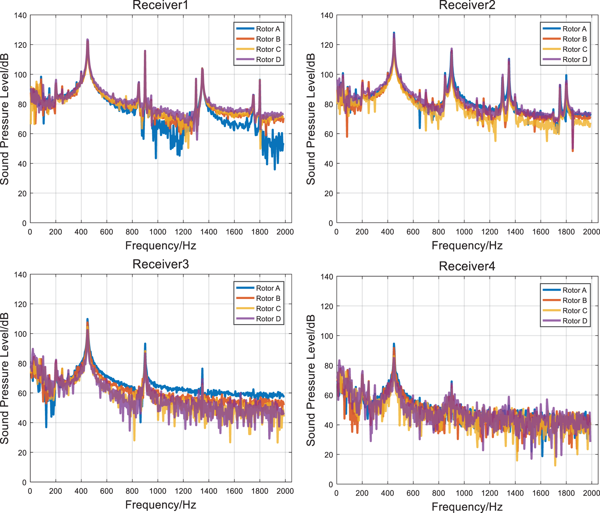
Figure 8: Frequency spectrum of sound pressure level of each measurement point
4.4 Overall Sound Pressure Level
The simulation results of the OASPL at the noise receivers around the fans in this study are summarized in Table 2. For the Receiver 3, the OASPL becomes smaller with the widths of the circular rings increasing in the axis direction. Meanwhile, except Receiver 3, the OASPL generated by Rotor C keeps the lowest in all of the 4 fans. This is corresponding to the phenomenon that Rotor C has the smallest size of the separation field around the blade tips from Rotor A to Rotor D.

The mass rate of the flow, the total pressure efficiency and the OASPL of the fans in this study, are given in Table 3. It is indicated that the mass flow rate of Rotor B is the lowest. Meanwhile, the total pressure efficiency of Rotor C is the highest, and the OASPL of the same rotor is the lowest at the most receivers. In a word, when the width of the circular rings cover near 2/3 of the width of the blade tips of the fan in the axis direction, the OASPL at the most receivers is the lowest, and the total pressure efficiency and the mass flow rate are better than the corresponding values for the original rotor without circular ring. The equations for the total pressure efficiency are summarized in the notation as:

The study on the influence of the width of the circular ring of a car cooling fan on the aerodynamic noise is conducted and it comes to the conclusion as follows:
(1) The OASPL of the aerodynamic noise caused by the fans could be reduced by changing the width of the circular ring. When the circular rings cover near 2/3 of the width of the blade tips of the fan in the axis direction, the OASPL at the most receivers is the lowest. Meanwhile, the total pressure efficiency and the mass flow rate are better than the corresponding values for the original rotor without the circular ring.
(2) With the widths of the circular rings of the fans increasing in the axis direction, the tip vortices around the trailing edges of blade tips became smaller and finally disappeared at last. Meanwhile, the separated flow fields arise gradually and become bigger around the middle of the junction of the blade tips and the circular rings. When the circular rings cover nearly 2/3 s of the width of the blade tips of the fan in the axis direction, the separated fields of the flow around the tips of the blades are the smallest. This corresponds to the phenomenon that the OASPL of the aerodynamic noise at the most receivers is the lowest in this situation.
However, only three typical widths of the circular rings are chosen in this study. In the future, more widths of the circular rings of the fans will be investigated. Also, the further study is still needed on whether the conclusion could be extended to the other type of fan, such as the fan with wing fences.
Funding Statement: This study is supported by the Guiding Project of Scientific Research Plan of Hubei Education Department of China [Grant No. B2020227].
Conflicts of Interest: The authors declare that they have no conflicts of interest to report regarding the present study.
References
1. Mellin, R. C. (1975). Axial flow fan and compressor mechanism of aerodynamic noise and flow parameters and structure. Noise Control Engineering, 4(1), 35–44. DOI 10.3397/1.2831986. [Google Scholar] [CrossRef]
2. Yasutoshi, S., Yoshio, K. (1973). Low noise axial flow fan. Bulletin of the JSME, 16, 1900–1910. DOI 10.1299/jsme1958.16.1900. [Google Scholar] [CrossRef]
3. Fukano, T., Kodama, Y., Senoo, Y. (1977). Low-pressure axial flow fan noise generated by one-turbulence noise model. Journal of Sound and Vibration, 50(1), 63–74. DOI 10.1016/0022-460X(77)90551-X. [Google Scholar] [CrossRef]
4. Fukano, T., Kodama, Y., Takamatsu, Y. (1978). Low noise axial flow fan of the second–the impact of the number of leaves, leaf chord length and angle. Journal of Sound and Vibration, 56(2), 261–277. DOI 10.1016/S0022-460X(78)80020-0. [Google Scholar] [CrossRef]
5. Roy, S., Cho, P., Perie, F. (1999). Designing axial flow fan for flow and noise. SAE Technical Paper Series, 1999(1), 1–4. DOI 10.4271/1999-01-2817. [Google Scholar] [CrossRef]
6. Longhose, R. E. (1977). Noise mechanism separation and design considerations for low tip-speed, axial-flow fans. Journal of Sound and Vibration, 53, 25–45. DOI 10.1016/0022-460X(77)90092-X. [Google Scholar] [CrossRef]
7. Duncan, P. E., Dawson, B. (1974). Reduction of interaction tones from axial flow fans by suitable design of rotor configuration. Journal of Sound and Vibration, 33(2), 143–154. DOI 10.1016/S0022-460X(74)80102-1. [Google Scholar] [CrossRef]
8. Longhouse, R. E. (1976). Noise mechanism separation and design considerations for low tip-speed, axial-flow fans. Journal of Sound Vibration, 48(4), 461–474. DOI 10.1016/0022-460X(76)90550-2. [Google Scholar] [CrossRef]
9. Sun, X. F. (1986). The aeroacoustic nature of the unequally spaced fan. Journal of Beijing University of Aeronautics and Astronautics, 1986(4), 137–145. [Google Scholar]
10. Han, W. J., Cai, D. Y., Xu, W. Y., Wang, Z. Q. (1989). An experimental study of effect of endwalls’ and blade surfaces’ static pressure distribution on cascade aerodynamic characters. Journal of Engineering Thermophysics, 10(3), 273–276 (in Chinese). [Google Scholar]
11. Moreau, S., Bennett, E. (1997). Improvement of fan design using CFD. SAE Technical Paper 970934. [Google Scholar]
12. Coggiola, E., Dessale, B., Moreau, S., Broberg, R., Bakir, F. (1998). CFD based design for automotive engine cooling fan systems. SAE Technical Paper 980427. [Google Scholar]
13. Henner, M., Kessaci, S., Moreau, S. (2002). Latest improvements of CFD models of engine cooling axial fan systems. SAE Technical Paper 2002-01-1205. [Google Scholar]
14. Kohri, I., Kobayashi, Y., Matsushima, Y. (2010). Prediction of the performance of the engine cooling fan with CFD simulation. SAE Technical Paper 2010-01-0548. [Google Scholar]
15. Kobayashi, Y., Kohri, I., Matsushima, Y. (2011). Study of influence of MRF method on the prediction of the engine cooling fan performance. SAE Technical Paper 2011-01-0648. [Google Scholar]
16. Oh, K. J., Kang, S. H. (1999). A numberical investigation of the dual performance characteristics of a small propeller fan using viscous flow claculations. Computers & Fluids, 28(6), 815–823. DOI 10.1016/S0045-7930(98)00035-8. [Google Scholar] [CrossRef]
17. Morris S, C., Good J, J., Foss J, F. (1988). Velocity measurements in the wake of an automotive colling fan. Experimental Thermal a Fluid Science, 17(1–2), 100–106. DOI 10.1016/S0894-1777(97)10054-1. [Google Scholar] [CrossRef]
18. Zhao, Y. Z. (2007). CFD analysis and low-noise optimization design on vehicle engine cooling fan (Master Thesis). Jilin University, China. [Google Scholar]
19. Jang, C. M., Furukawa, M., Inoue, M. (1998). Noise reduction by controlling tip vortex in a propeller fan. ASME Journal of Turbomachinery, 120(3), 454–464. [Google Scholar]
20. Nashimoto, A., Akuto, T., Nagase, Y., Fujisawa, N. (2003). Aerodynamic noise reduction by use of a cooling fan with winglets. SAE Technical Paper 2003-01-0531. [Google Scholar]
21. Nashimoto, A., Fujisawa, N., Akuto, T., Nagase, Y. (2004). Measurements of aerodynamic noise and wake flow field in a cooling fan with winglets. Journal of Visualization, 7(1), 85–92. DOI 10.1007/BF03181488. [Google Scholar] [CrossRef]
22. Ota, H., Yuichi, K., Yukio, O., Hiroshi, Y. (2005). Development of high efficient radiator cooling fan for automotive application. SAE Paper 2005–01–2067. Detroit, Michigan, USA. [Google Scholar]
23. Tang, Y. W. (2007). Study on aerodynamic performance and aero-acoustic performance of engine cooling fan (Master Thesis). Jilin University (in Chinese). [Google Scholar]
24. Mo, W. B. (2015). A study on the effect of the structure and parameters of engine annular cooling fans on performances (Master Thesis). South China University of Technology (in Chinese). [Google Scholar]
25. Shangguan, W. B., Mo, W. B., Shu, H. T., Yu, N., He, P. Y. et al. (2017). Study on the effect of the structure and parameters of engine annular cooling fans on the aerodynamic performances. Chinese Internal Combustion Engine Engineering, 38(1), 56–62 (in Chinese). [Google Scholar]
26. Bian, T., Shen, X., Feng, J. (2021). Numerical study of the influence of splitter geometry on secondary flow control. Proceedings of the Institution of Mechanical Engineers, Part A: Journal of Power and Energy, 235(4), 643–650. [Google Scholar]
27. Bian, T., Shen, X., Wang, B., Feng, J., Han, Q. P. (2019). Numerical and experimental investigations of flow loss and flow structure of circular Arc cambered plate blade cascade. Proceedings of the Institution of Mechanical Engineers, Part A: Journal of Power and Energy, 233(8), 961–973. DOI 10.1177/0957650919846006. [Google Scholar] [CrossRef]
28. Bian, T., Shen, X., Feng, J., Wang, B. (2020). Numerical investigation on the secondary flow control by using splitters at different positions with respect to the main blade. Fluid Dynamics & Materials Processing, 17(3), 615–628. DOI 10.32604/fdmp.2020.06613. [Google Scholar] [CrossRef]
29. Zhu, H. J. (2015). FLUENT15.0 practical study on the flowfield analysis. Beijing: Posts & Telecom Press (in Chinese). [Google Scholar]
30. Lighthill, M. J. (1982). On sound generated aerodynamically: I general theory. Proceedings of the Royal Society London A., 211(1107), 564–587. [Google Scholar]
31. John, D., Anderson, J. R. (1995). Computational fluid dynamics: The basics with applications. Mechanical Engineering Series, 261–262. [Google Scholar]
32. Menter, F. L. O. R. I. A. N. R. (1993). Zonal two equation kw turbulence models for aerodynamic flows. 23rd Fluid Dynamics, Plasmadynamics, and Lasers ConferenceOrlando Florida. [Google Scholar]
33. Jiang, F., Ma, J. M. (2013). Noise analysis of different opening nozzle model based on FLUEN. Aeronautical Computing Technique, 43(3), 961–973 (in Chinese). [Google Scholar]
34. ANSYS Inc. (2013). ANSYS FLUENT User’s Guide Release 15.0. 2013 ANSYS Inc. [Google Scholar]
35. Cao, Y. T. (2009). CFD analysis and optimization design for engine cooling fan performance of heavy-duty truck (Master Thesis). Jilin University (in Chinese). [Google Scholar]
 | This work is licensed under a Creative Commons Attribution 4.0 International License, which permits unrestricted use, distribution, and reproduction in any medium, provided the original work is properly cited. |