| Fluid Dynamics & Materials Processing |
DOI: 10.32604/fdmp.2023.020076
ARTICLE
Numerical Analysis of Residual Strength in the Perforated Casing of Ultra Deep Wells
1Engineering Technology Research Institute of Petro China Xinjiang Oilfield Company, Karamay, 834000, China
2School of Petroleum Engineering, China University of Petroleum (East China), Qingdao, 266580, China
3SINOPEC Xinan Oilfield Service Corporation, Deyang, 618000, China
4SINOPEC Southwest China Oil & Gas Company, Chengdu, 610041, China
*Corresponding Author: Yuqiang Xu. Email: auyuqiang@163.com
Received: 02 November 2021; Accepted: 22 December 2021
Abstract: A three-dimensional model for the numerical simulation of casing-cement behavior is used to investigate residual strength in the perforated casing of ultra deep wells. The influence of the hole diameter, hole density and phase angle on the residual strength of the casing under non-uniform stress and fracturing conditions is revealed through the consideration of different perforation parameters. It is shown that the residual strength of the casing increases with the hole diameter and periodically changes with the hole density; the phase angle is the main factor that affects the residual strength of the perforated casing, and the perforation should be avoided in the direction of the minimum principal stress to reduce stress concentration at the perforation hole. Moreover, as shown by a companion orthogonal experiment, the descending order of influence of the different influential parameters is: phase angle, hole diameter, hole density and the thickness of casing.
Keywords: Perforated casing; non-uniform stress; residual strength; orthogonal experiment
A high and nonuniform in situ stress exists in ultradeep wells. The influence of perforation and reservoir stimulation on the residual strength of the casing is unclear. The optimization of perforation schemes lacks a scientific basis. Therefore, one of the key issues is to optimize the perforation casing design of ultradeep wells, which urgently needs to be solved in the development of ultradeep formations. Scholars at home and abroad have studied the strength of perforated casings based on theoretical calculations, numerical simulations, and laboratory experiments. Zong et al. [1] calculated the collapse pressure of a nonperforated casing by Ilemenko’s method and deduced the reduction coefficient of the anti-collapse capacity of a perforated casing, which is in good agreement with the calculated value of the experimental research results. Somerville et al. [2] used numerical simulation and theoretical formulas to calculate and analyze the factors affecting casing stability after perforation completion. Fereidoun et al. [3] analyzed the stress concentration around the perforation hole of a spiral perforation casing. Li et al. [4] used ANSYS finite element software to analyze the impact of repeated perforation on casing strength. The maximum strength reduction was 16.35%, and the average amplitude was 11.43%. Zachary et al. [5] proposed a novel method for the acquisition of yield strength in the hoop direction and carried out an experimental study through the determination of the tubular yield strength in the hoop direction. In addition, related studies [6–8] have analyzed the strength of perforated casings under different working conditions. However, due to different analysis objects, working conditions, experimental conditions and simulation methods, they cannot be closely integrated with actual field data. Therefore, this paper establishes a three-dimensional casing-cement-formation model based on actual high in situ stress and fracturing conditions of ultradeep wells in the southern margin of the Junggar Basin, Xinjiang, which aims to comprehensively study the influence law of perforation parameters on casing strength under a nonuniform in situ stress and to put forward optimization suggestions to provide theoretical support for wellbore integrity protection in this area.
2 Three-Dimensional Model of Perforated Casing-Cement-Formation under Heterogeneous in Situ-Stress Conditions
Since casing-cement-formation under perforation conditions is not axisymmetric or centrally symmetrical, only a three-dimensional model can be selected to analyze the overall stresses under a nonuniform stress.
This model takes the 5-1/2” oil layer casing of Well G101 as the research object, which is at a depth of 6600 m, in a certain area of Xinjiang. Its basic perforation parameters are a diameter of 13 mm, 16 holes/m, phase angle of 90°, and hole depth of 500 mm. The formation is simplified from inside to outside, and there are four parts: perforated casing, perforated cement, perforated formation, and outer formation.
Certain assumptions are introduced into the model to lower the difficulty of modeling and calculation, considering that the specific condition of a real perforated casing is more complicated in the formation. The specific assumptions are as follows: there is no eccentricity of the perforation hole, and the central axis of the hole is perpendicular to and intersects with the axis of the casing; the projection on the vertical plane of the axis of the perforation is a circle and the burrs and cracks on the edge of the hole are not considered; the ellipticity and wall of the casing are ignored. The thickness unevenness, casing, cement, and formation are homogeneous elastomeric materials.
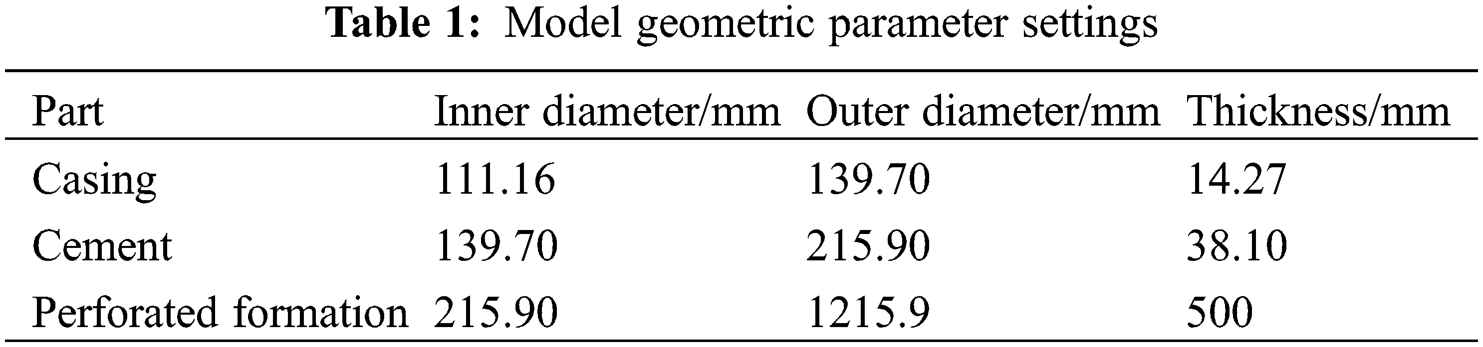
A three-dimensional model of casing-cement-formation is established based on the above assumptions. The length, width, and height are 5 m, 5 m, and 0.7 m, respectively, as shown in Fig. 1, and the geometric parameters of each part are shown in Table 1.
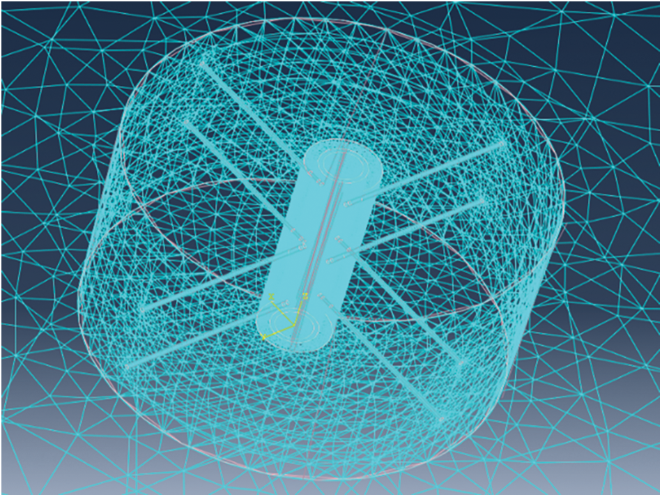
Figure 1: Casing-cement-formation model
To prevent rigid body displacement of the model from causing nonconvergence in the calculation, the author used heterogeneous ground stress data and fracturing construction data in the southern margin area to set the boundary conditions, and the x and y directions in the outer boundary of the model are set perpendicular to a single surface of the x- and y-axes. The displacement is fixed, minimum and maximum horizontal ground stresses are applied to opposite surfaces, and the z-axis direction displacement of the upper and lower surfaces is fixed. At the same time, pressure is applied to the inner wall of the casing and perforation hole; the direct interface of the formation, casing, and cement is connected by binding.
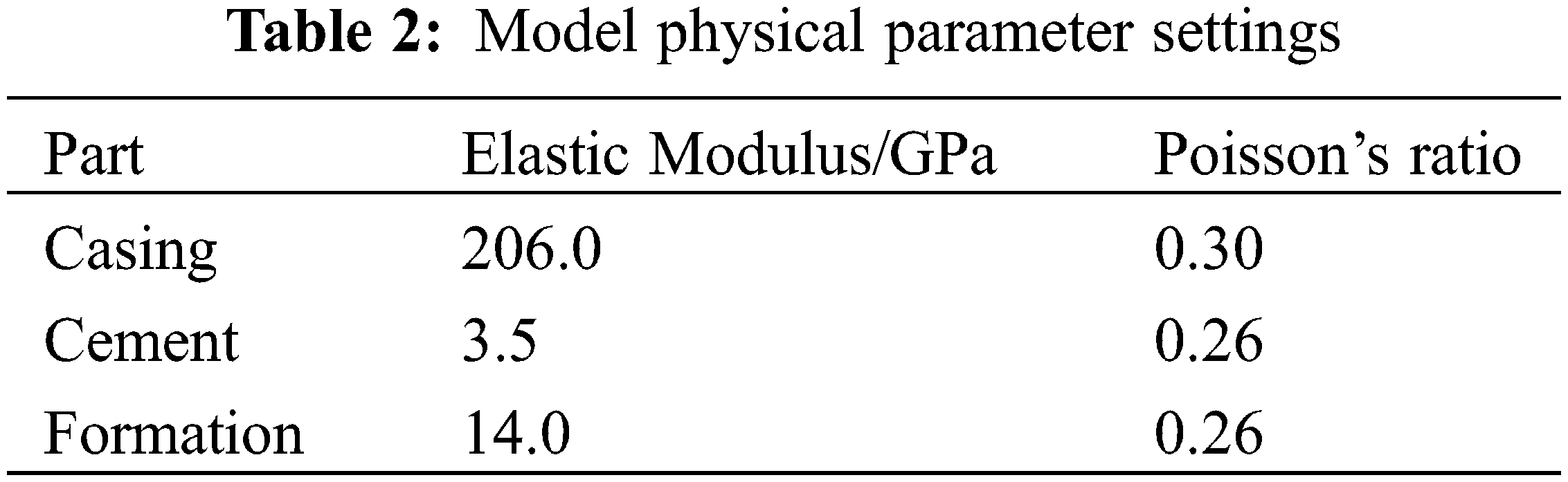
According to field data, the maximum horizontal ground stress is 167.88 MPa, the minimum horizontal ground stress is 144.51 MPa, and the internal pressure during fracturing is approximately 120 MPa. According to the finite element calculation steps, four geometric model components—perforation casing, perforated cement, perforated formation and external formation—are established in sequence; the actual data are selected to set the material parameters of each part of the model (see Table 2); and the load and constraints are set. To reduce the difficulty of model calculation, the researchers use tetrahedral mesh for mesh division, refine the mesh density at the perforations (reducing the mesh size will no longer affect the calculation results), adjust the boundary layout of each component to make the mesh transition smoothly, and use static analysis and calculation to obtain nonuniform ground stress conditions. The equivalent stress cloud diagram of the perforating casing is obtained.
To verify the accuracy of the model, the collapse strength of the N80 casing under different perforation conditions was tested due to the limitation of the experimental conditions. The casing size parameters and perforation parameters are shown in Table 3 below. The finite element model is verified by comparing the yield load of the casing between the finite element model and the experiment.
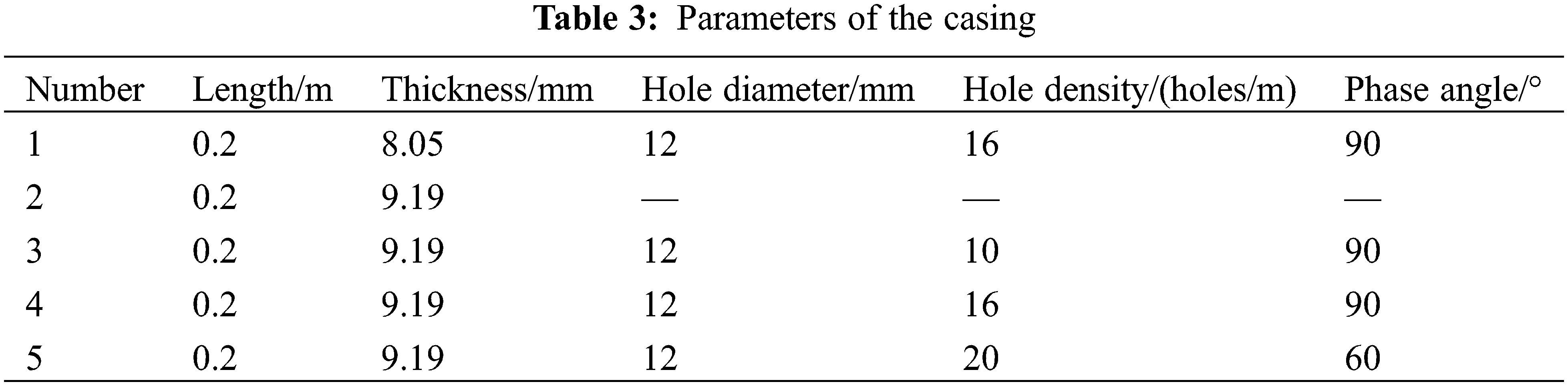
The results show that the simulated failure loads are higher than the experimental data, but the trend of the load line is basically the same (Fig. 2). The maximum calculation error of the finite element model is no more than 11%, which has a certain practical significance.
Figure 2: Validation curve
3 Analysis of the Influence of Perforation Parameters on Residual Strength of the Casing under Nonuniform Ground Stress Conditions
According to field perforation plan data, the parameters of different hole diameters, hole densities, phase angles, etc., were selected within a certain range, and the basic perforation parameters of the oil layer casing of the G101 well were compared to analyze each perforation under nonuniform in situ stress conditions and the influence of the parameters on the casing strength.
To visually characterize the change law of the perforating casing strength, the normal form equivalent stress of the fourth strength theory (von Mises stress) is used as an evaluation index. The normal form equivalent stress uses stress contours to represent the stress distribution inside the model. The most dangerous area in the model can be quickly determined, and the specific expression is shown in Eq. (1).
In the formula,
The difference between the yield stress of the casing material and the maximum equivalent stress under simulated conditions is regarded as the residual strength of the casing [5–7]. The oil layer casing steel grade of Well G101 is TP140V, and the yield stress is 1040 MPa [9].
The researchers select diameters of 7, 10, 13, and 16 mm to establish the casing-cement-formation 3D models, simulate and calculate the equivalent stress cloud diagram of the perforated casing (Fig. 3), obtain the corresponding maximum equivalent stress according to the equivalent stress cloud diagram, calculate the residual strength of the perforated casing under different hole diameters, and draw the curve of the influence of the hole diameter on the maximum equivalent stress and residual strength of the perforated casing (Fig. 4).
Figure 3: Stress cloud diagrams of casings with different bore diameters
Figure 4: The relationship between the maximum equivalent stress and residual strength of the casing and the change in the hole diameter
Fig. 3 shows that the maximum equivalent stress under nonuniform in situ stress conditions is generated at perforation holes on the inner wall of the casing. Fig. 4 shows that the maximum equivalent stress of the perforated casing under nonuniform in situ stress conditions increases with the diameter of the perforation. It shows a decreasing trend, that is, the smaller the hole diameter is, the more serious the stress concentration is. The residual strength of the casing increases with the diameter of the casing, with a small change of approximately 75 MPa, and the equivalent stress in each area of the casing does not reach the yield stress of 1040 MPa.
Casing-cement-formation 3D models under different hole densities of 8, 12, 16, 20 24 holes/m are established. The maximum equivalent stress of the casing under different hole densities is obtained according to the equivalent stress cloud diagram, and the curves of the influence of the hole density on the maximum equivalent stress and residual strength of the perforated casing are drawn (Fig. 5).
Figure 5: The relationship between the maximum equivalent stress and residual strength of the casing and the change in hole density
Fig. 5 shows that the maximum equivalent stress of the perforated casing and residual strength of the casing under the condition of a nonuniform in situ stress show a nonmonotonic change trend with increasing hole density, and the change range is approximately 20 MPa, which shows the selected hole density. Under the parameter conditions, increasing the hole density will not have a monotonous weakening effect on the casing strength. This phenomenon is explained as an increase in hole density to a certain extent, which can be used to produce perforation on the inner wall of the casing with the help of internal pressure under fracturing conditions. The support effect offsets the weakening of the strength of the pipe after perforation, but if the hole density is increased blindly, the strength of the casing will still be reduced.
The perforation phase angles are 45°, 60°, 90°, 120°, and 180°, and the model building method and curve drawing method are the same as those for the hole diameter and hole density. The influence of the phase angle on the strength of the perforated casing is shown in Fig. 6.
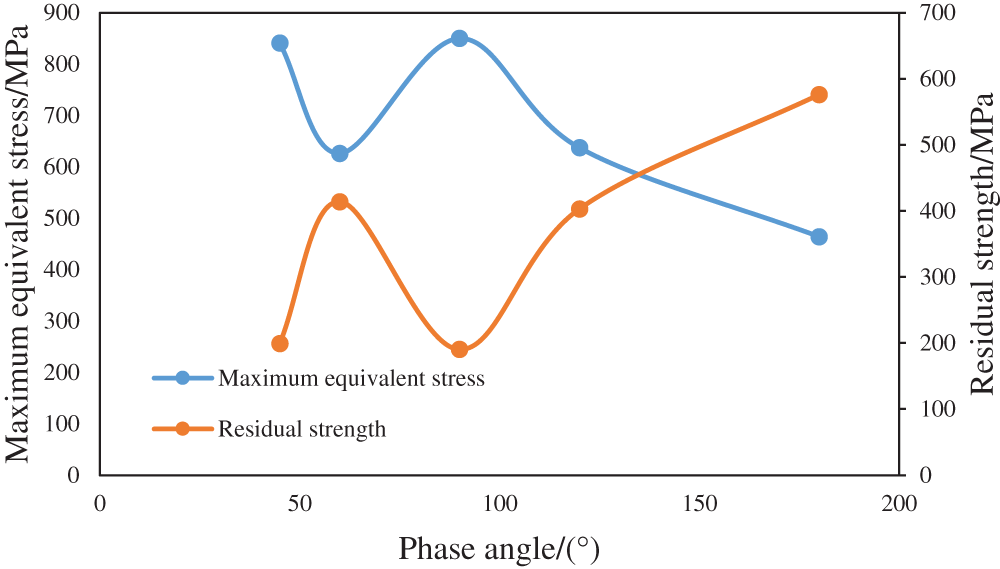
Figure 6: Variation in the maximum equivalent stress and residual strength of the casing with the phase angle
Fig. 6 shows that when the phase angle is 180°, the maximum equivalent stress of the perforated casing is the smallest, and the residual strength of the casing is the highest. The effects of 45° and 90° and 60° and 120° on the strength of the casing are basically the same. Under this condition, the perforation phase affects the casing strength with a range of approximately 380 MPa, which indicates that the phase angle has a key influence on the casing strength. Therefore, perforating schemes under different phase angles are further compared.
Under the condition of a certain hole diameter or hole density, 40 sets of perforation schemes are designed to establish a three-dimensional model and calculate the maximum equivalent stress. According to the equivalent stress cloud diagram under different phase angle conditions, the maximum equivalent stress drawing curve is obtained (see Figs. 7 and 8).
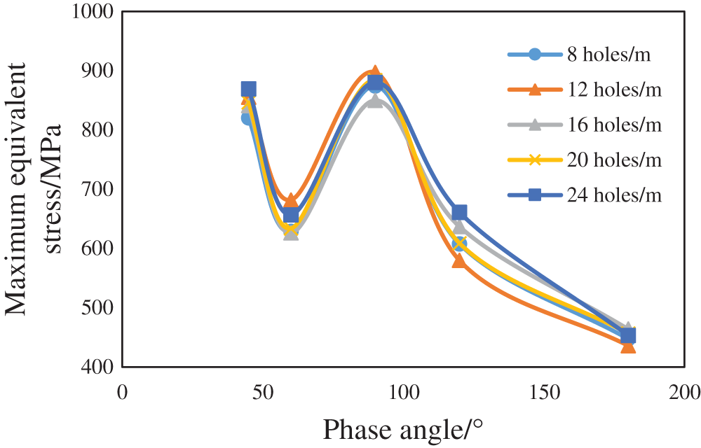
Figure 7: Variation in the maximum equivalent stress of various perforation schemes with the phase angle (the hole diameter is constant)
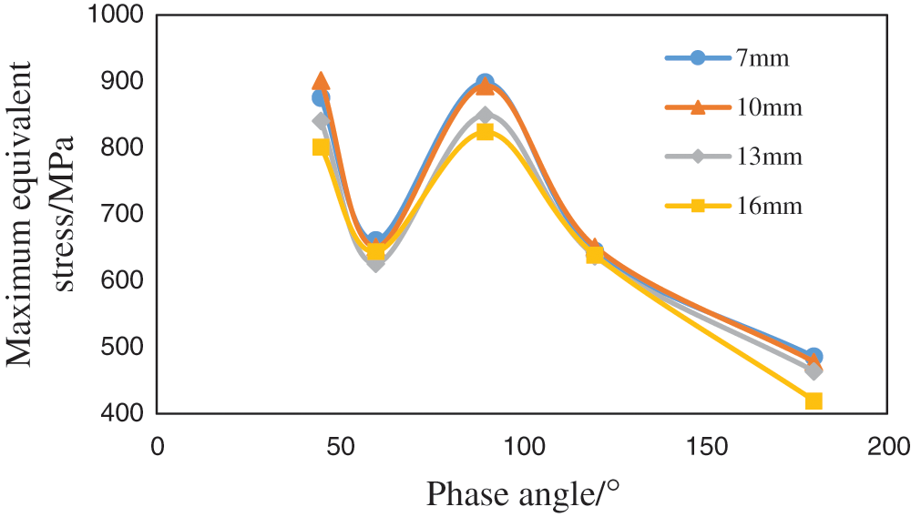
Figure 8: Variation in the maximum equivalent stress of various perforation schemes with the phase angle (the hole density is constant)
It can be seen from the calculation results that the influence of the phase angle on the strength of the casing will not change when the hole diameter or hole density is constant, the maximum equivalent stress of the casing is the smallest at a phase angle of 180°, the remaining strength of the casing is the highest, and the stress in each area of the casing under each scheme does not reach its material yield stress of 1040 MPa. Taking the perforation parameters of a diameter of 13 mm, 16 holes/m, and phase angle of 90° as an example, the stress cloud diagram shows that the stress concentration on the inner wall of the casing is the most serious (see Fig. 9a for details). The stress concentration phenomenon of the borehole toward the maximum horizontal ground stress mainly occurs on the outer wall of the casing, and its value is less than 50% of the maximum equivalent stress (see Fig. 9b for details).
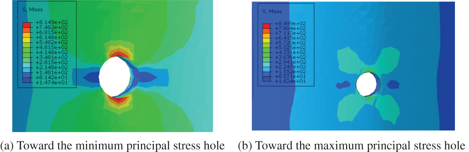
Figure 9: Stress concentration phenomenon of holes in different directions
Since the minimum principal stress direction of this model is the x-axis direction, there will be holes in the direction of the minimum principal stress when the phase angle is 45° and 90°, resulting in a larger equivalent stress. There is no perforation with a small principal stress direction in the perforation direction when the phase angle is 60°, 120° and 180°, and perforations are perpendicular to the phase angle when the phase angle is 180°. Therefore, in principle, no matter what phase angle is used, the perforation direction toward the minimum principal stress direction should be avoided, which can greatly improve the stress concentration phenomenon at the perforation.
4 Optimization of the Perforation Scheme Based on Orthogonal Experiments
To further quantify the influence of various factors on the strength of the perforated casing and to judge the influence of each factor on the residual strength of the perforated casing, this paper chooses the method of combining orthogonal experiments and range analysis. An orthogonal test is an efficient and concise test method to explore optimal parameter combinations for multifactor tests. For most complicated tests with more than 3 parameters that need to be optimized, if a comprehensive test is carried out, the test scale is large, the implementation is difficult, and the analysis processes are very cumbersome [10,11]. Orthogonal experiments select the most representative combination from all combinations of test factors to conduct the test, which greatly reduces the number of experiments.
Based on the aforementioned research and considering the influence of wall thickness on the strength of the casing, the factors of the orthogonal experiment are determined as the casing wall thickness, hole diameter, hole density, and phase angle. Four factors are selected for each factor. For the four-level experiment, the specific factor level table is shown in Table 4. The L16 (45) orthogonal table is selected for the experiment, and the calculated experimental results are shown in Table 5. In the table, K represents the sum of experimental results of a certain level of experiment with a certain factor, k is the arithmetic mean of K corresponding to a certain factor at a certain level, and R is the range of each factor.
This paper compares the magnitude of range R of different factors and judges the influence of each factor on the residual strength. From the calculation results, it can be seen that RC > RA > RB > RD > RE, so the influence on residual strength in descending order is the phase angle, hole diameter, hole density, and wall thickness. At the same time, the higher the k value is, the better the level of a certain factor. The calculation results show that the initial hole diameter is 16 mm, the hole density is 24 holes/m, the phase angle is 180°, and the casing wall thickness is 15.11 mm under the experimental conditions. This is a combination of advantages. However, according to engineering experience, a phase angle of 180° is not widely used, which may cause problems such as insufficient formation opening and streamline concentration. It is recommended that the k value should be slightly lower than the phase angle of 180°, and a perforation phase angle of 120° is used more commonly. In the end, the preferred exit perforation scheme is a diameter of 16 mm, 24 holes/m, phase angle of 120°, and casing wall thickness of 15.11 mm. The final scheme calculates the residual strength to be 517.9 MPa, which can meet engineering requirements.
(1) To study the influence of perforation parameters on casing strength under the condition of a heterogeneous in situ stress in ultradeep wells, a three-dimensional model of casing-cement-formation was established, and the stress distribution cloud map of the perforated casing was calculated and analyzed based on this model. The model considers the effect of the combined action of the formation and cement on the stress distribution of the casing.
(2) This paper analyzes the influence of perforation parameters on the casing strength, such as the hole diameter, hole density, and phase angle. The study found that under high and nonuniform ground stress and fracturing construction conditions, due to internal pressure, the increase in the large hole diameter and hole density will not greatly reduce the strength of the casing, and the perforation phase angle is the main factor affecting the strength of the casing. It is recommended that the direction of perforation toward the direction of the minimum principal stress should be avoided to prevent stress concentration at the perforation.
(3) This paper quantitatively analyzes the influence of each perforation parameter and casing wall thickness on the residual strength through orthogonal experiments and obtains the phase angle, hole diameter, hole density, and casing wall thickness in descending order of influence. Combined with range analysis, the final optimal plan is a hole diameter of 16 mm, hole density of 24 holes/m, phase angle of 120°, and casing wall thickness of 15.11 mm. The residual strength of the casing under this plan is calculated as 522.1 MPa, which can meet engineering requirements.
Acknowledgement: Thanks are due to the supported by Engineering Technology Research Institute of Petro China Xinjiang Oilfield Company and China University of Petroleum (East China).
Funding Statement: This work was supported by the National Natural Science Foundation of China [52074326].
Conflicts of Interest: The authors declare that they have no conflicts of interest to report regarding the present study.
References
1. Zong, Y. X., Zhao, H. W., Bu, J. (1988). Experimental study on anti-collapse ability of casing in perforated section of reservoir. Acta Petrolei Sinica, 4, 87–100. [Google Scholar]
2. Somerville, J. M., Samsuri, A. B. (1991). Perforation stability-physical and numerical modeling. SPE91-763. [Google Scholar]
3. Fereidoun, A., Parfitt, S. H. (1998). A simple model for collapse and post collapse behavior of tubulars with application to perforated and slotted liners. Drilling & Completion, 13(3), 190–196. DOI 10.2118/51188-PA. [Google Scholar] [CrossRef]
4. Li, M. F., Xu, F., Dou, Y. H., Zhang, W. J. (2018). Strength safety analysis of repeated perforation casing under fracturing conditions. Petroleum Machinery, 46(9), 92–99. [Google Scholar]
5. Zachary, C., Bello, O., Teodoriu, C. (2021). Calculation and prediction of casing collapse strength based on a new yield strength acquisition method. Journal of Natural Gas Science and Engineering, 95(1), 104149. DOI 10.1016/j.jngse.2021.104149. [Google Scholar] [CrossRef]
6. Smith, M. B., Pattillo, P. D. (1983). A finite element analysis of collapse of perforated casing. Journal of Pressure Vessel Technology, 105(3), 234–240. DOI 10.1115/1.3264270. [Google Scholar] [CrossRef]
7. Hair, C. C., Schwind, B. E. (1993). Evaluation and design optimization of perforated casing. Offshore Technology Conference, Houston, Texas. OTC-7345-MS. [Google Scholar]
8. Dastgerdi, M. E., Manshad, A. K., Mohammadi, A. H. (2020). Optimization of perforated liner parameters in horizontal oil wells. Journal of Petroleum Exploration and Production Technology, 10(8), 3505–3514. DOI 10.1007/s13202-020-00951-z. [Google Scholar] [CrossRef]
9. Lu, X. Q., Zhong, S. M., Li, J. (2011). Design, development and application of ultra-high strength petroleum casing TP140V for ultra-deep and complex wells. Steel Pipe, 40(5), 26–30. [Google Scholar]
10. Fang, K. T., Ma, C. X. (2001). Orthogonal and uniform experimental design. China: Science Press. [Google Scholar]
11. Huang, G. T., Zhang, S. C. (2008). Productivity prediction and optimal design of fractured wells in mid-high permeability gas reservoirs. Journal of China Coal Society, 33(5), 543–546. [Google Scholar]
 | This work is licensed under a Creative Commons Attribution 4.0 International License, which permits unrestricted use, distribution, and reproduction in any medium, provided the original work is properly cited. |