| Fluid Dynamics & Materials Processing |
DOI: 10.32604/fdmp.2023.021118
ARTICLE
Experimental Investigation of Regular or Wavy Two-Phase Flow in a Manifold
1Sionpec Shengli Oilfield Company, Dongying, 257000, China
2Technical Inspection Center, Sionpec Shengli Oilfield Company, Dongying, 257000, China
3Offshore Oil Engineering Co., Ltd., Dongying, 257000, China
*Corresponding Author: Lihui Ma. Email: malihui1128@163.com
Received: 28 December 2021; Accepted: 24 January 2022
Abstract: An experimental study was conducted to investigate the properties of stratified regular or wavy two-phase flow in two parallel separators located after a manifold. A total of 103 experiments with various gas and liquid velocity combinations in three inlet pipes were conducted, including 77 groups of outlet pipe resistance symmetry and 26 groups of outlet pipe resistance asymmetry trials. The experimental results have revealed that when the gas-liquid flow rate is low, the degree of uneven splitting is high, and “extreme” conditions are attained. When the superficial gas velocity is greater than that established in the extreme case, the direction of the liquid-phase displacement is reversed, while that of the gas remains unchanged. Thus, the degree of gas phase bias tends to be mitigated with an increase in the gas velocity, while the uneven splitting degree of liquid approaches 10%. Finally, varying the gas-phase outlet pipe resistance is shown to effectively change the gas-liquid two-phase flow distribution.
Keywords: Uneven phase distribution; two-phase flow; manifold; asymmetric resistance
Gas-liquid two-phase flow has been common in many fields of materials science [1]. In particular, the phenomenon of uneven phase distribution commonly occurs in a gas-liquid two-phase flow. This phenomenon can be used as a phase separator in a production system, and a complex manifold composed of simple T-shaped pipes can be employed for liquid-liquid or gas-liquid pre-separation to reduce the pressure of the subsequent processing equipment, as well as for measuring the multiphase fluid. However, the generation of uneven splitting in parallel pipelines will exert adverse effects on downstream production equipment. For instance, mal-distribution in the petroleum industry might reduce the working efficiency of the downstream installation, make certain downstream equipment overload or underload, accelerate equipment wear, or even cause accidents. For the latter, due to many conditions related to the production and processing system, it is not easy to maintain. To reduce the damage caused by uneven flow distribution, the previous studies have typically used the redundancy capacity of oil and gas processing equipment after the manifold to adapt to the flow fluctuation in a larger range. However, this method increases the volume of equipment and production costs and reduces production efficiency. Moreover, in certain cases, this method is even unapplicable, and an uneven inflow can cause severe damage to the separator and other equipment. Therefore, this method cannot be used to solve the problem of uneven phase distribution.
The problem of uneven distribution of a gas-liquid two-phase flow has been widely studied since Oranje et al. [2] published the article entitled “Condensate Behavior in Gas Pipelines is Predictable” in 1973. In recent years, most studies have been focused on the phase distribution of a gas-liquid two-phase flow at three joints of the simplest diverter. Azropardi et al. [3] investigated the behavior of a gas-liquid two-phase flow in the impacting T-junction and concluded that the flow behavior at the T-junction was complex, which was caused by the phase inertia. Wern et al. [4] found that the extended insertion depth and the direction of the inner branch of a large-diameter impact tee have different effects on the gas-liquid two-phase flow in the tee. In addition, Yin et al. [5] studied the slug initiation and initial development behavior in hilly-terrain pipeline at a low superficial liquid velocity.
For the impact T-junction with two outlet arms connecting the riser, Liu et al. [6] showed that the inlet and outlet pressures had a great influence on the gas-liquid two-phase mass flow rate. Ma et al. [7] numerically simulated the gas-liquid two-phase flow distribution in a branch pipeline, demonstrating that, at the same outlet pressure, the gas-liquid two-phase flow was always in a uniform distribution state. Ma et al. [8,9] explored the asymmetry of the downstream pipeline with the aim to obtain the equal gas-liquid ratio separation of the gas-liquid two-phase flow. Azzopardii et al. [10] studied the effect of the flow state in risers on the gas-liquid two-phase flow splitting.
It is challenging to predict the phase distribution of a gas-liquid two-phase flow in the outlet pipeline after flow through the complex manifold. This is because the manifold structure is composed of various types of tees, and the behavior of the two-phase flow at tees is very complex. Taitel et al. [11] studied the flow distribution of the gas and liquid in four parallel pipes under various gas and liquid flow rates and inclinations angles. Manabu et al. [12] analyzed two different manifold structures, namely, a horizontal inlet pipe with four risers and a vertical main inlet pipe with five horizontal branches. The analysis showed that the flow distribution of each type of pipe was mainly affected by the flow parameters, specifically the flow velocities of the two phases at the beginning of the incoming main pipe. Horiki et al. [13] investigated the relationship between the length of the branch pipe and the liquid recovery rate in the horizontal manifold with four risers. Lee et al. [14,15] claimed that, under the condition of annular flow, adjusting the insertion lengths of branch pipes could enable achieving the uniform liquid flow distribution in parallel horizontal pipes. The above-mentioned studies have been focused on the manifold with one main pipe, multiple parallel branches, and the flow direction along the axial direction of the main pipe. In the modern industry, there have been multiple incoming pipes introduced along different directions. However, in such pipelines, flow patterns are not stable, and the inclination of the branch pipe changes in different situations, resulting in a more complex manifold structure.
Due to the complexity and high cost of maintenance, the pipeline structure has high requirements. Moreover, the transformation methods of a tee structure proposed in the previous studies are too complex for actual large-scale production. Therefore, predicting the phase distribution of a two-phase flow in a manifold and proposing an efficient controlling method of the bias flow have become urgent problems. Based on the specific structure of a subsea manifold, this study aims to explore the gas-liquid two-phase flow pattern in a parallel separator for different gas-liquid velocity combinations, as well as the flow state of the gas-liquid two-phase flow in a pipeline, which can provide a useful reference for relevant practical production.
The manifold was composed of several impacting tees and branching T with different directions. The experiments were performed using a specific flow facility with three parallel inlet pipes and two outlets. The configuration of the loop is presented in Fig. 1.

Figure 1: Schematic flow configuration (1) Air compressor (2) Buffer tank (3) Gas Flowmeter (4) Water tank (5) Water pump (6) Filter (7) Inlet pipes (8) Separator 1 (9) Separator 2 (10) ESP
The gas-liquid two-phase flow passed through the 15.2-m plexiglass inlet pipes, which were installed upstream of the specific manifold. The pipe diameters were 0.03, 0.04, and 0.03 m. The inlet pipe was relatively long to ensure that the flow was fully developed. The outlet pipeline had a symmetrical structure. After the horizontal manifold, two risers were installed in front of the separators. All pipes were transparent so that the gas-liquid two-phase flow behavior in the pipes could be observed.
The measurements were performed at room temperature under the normal air pressure using the water as a gas and a liquid. The air compressed by the compressor was first sent to the air buffer tank and then to the diverter after metering. The flow distribution was controlled by the valves placed in the three branches. The water in the water tank was pumped into the liquid pipeline with a centrifugal pump at the beginning of the measurement, and then flowed through the liquid shunt structure after passing the mass flowmeter. Finally, it was distributed to three branches according to a certain flow demand. After single-phase separation, the two-phase flow was fully formed in the inlet pipes and then entered the experimental section. The gas-liquid two-phase flow was redistributed in the experimental manifold. After passing through a section of the horizontal pipe after the risers, the two-phase flow entered the separator. The gas and liquid phases were separated in the separator. The gas was released into the atmosphere through the gas outlet pipe at the top of the separator after being metered. Meanwhile, the liquid phase-water mixture flowed through the water outlet pipe at the lower part of the separator and was released into the temporary storage tank after being metered. Finally, water was delivered to the water tank with an electric submersible pump to realize the water recycling.
The manifold was designed according to the commonly used form in the actual production. The inner diameters of the main pipe and two risers after the manifold were 40 mm, and those of the rest were 30 mm.
Assuming that the mass of the gas-liquid phase did not change in the whole test system and following the law of mass conservation, the mass flow and volume flow were respectively calculated by [16]:
where MGin1, MGin2, and MGin3 denote the mass flow values of the gas in the inlet pipes; MGout1 and MGout2 are the mass flow values of the gas in the outlet pipes; QLin1, QLin2, and QLin3 are the volume flow values in the inlet pipes; QLout1 and QLout2 are the volume flow values in the outlet pipes; MG0 and QL0 are the total mass flow values of the gas or liquid flow in a system.
In-line equations/expressions are embedded into the paragraphs of the text. For example, E = mc2. In-line equations or expressions should not be numbered and should use the same/similar font and size as the main text.
The recovery rate of a gas or a liquid, denoted by FG1 or FL1, respectively, which represented the fraction of the gas or liquid flow at one outlet accounting for the recovery rate of the total flow at the inlet, was defined as follows:
In the ideal case, the gas phase and liquid phase are evenly distributed, so the gas phase recovery rate and the liquid phase recovery rate will be both 0.5:
If the recovery rate deviates significantly from 0.5, it can be considered that the two-phase flows in two separators are unevenly distributed. According to the requirements imposed by the actual production on the liquid fluctuation in the parallel separator, a range of ±5% was selected as a tolerable fluctuation range of the recovery rate; namely, 0.45 < FrG1 and FrL1 < 0.55 were the tolerable values, where Fr denotes the fraction of the two-phase flow out from outlet 1.
In this study, a total of 103 groups of experiments were conducted at specific multiple relationships of the flow rates of the three incoming pipes. The flow deviation of the gas-liquid two-phase flow in the parallel pipe separator was studied under different gas-liquid velocity combinations and outlet pipe resistance conditions. Inlet pipe 1 was set as a reference; the gas and liquid mass flow rates of inlet 2 were three times those of inlet 1; the flow rates of inlet 3 were equal to those of inlet 1. Each experiment was repeated at least three times to eliminate the randomness of data, and the final results were averaged. The experiments were divided into three groups, as follows:
1) Single-phase fluid experiments
Only gas or liquid was used in these experiments to obtain the distribution law of a single-phase fluid. After the pipeline resistance or structural changes, this type of experiment was carried out first.
2) Resistance symmetry experiments of the outlet pipeline
A total of 32 experiments were conducted under different gas and liquid velocity combinations at the symmetric resistance of outlets. The superficial velocities of the water were 0.03, 0.05, 0.08, and 0.2 m/s, while the superficial velocities of the gas varied from 0.5 to 5.5 m/s.
3) Asymmetric resistance experiments of the outlet pipeline
The orifice plate was installed at the gas phase outlet of separator 1, while the other separator was kept unchanged. In this group of experiments, the fractions of the gas and liquid in the two separators were analyzed at the same superficial velocity of the water and gas under the resistance symmetry of the outlet pipes.
3.1 Single-Phase Fluid Experiment
The single-phase fluid experiment was performed at the beginning of the gas-phase (liquid-phase) valve installed in the gas-liquid mixing section, which was closed, regulating the liquid (gas phase) superficial velocity. The gas-liquid flow rate in inlet 1 represented the same parameter in the system. The liquid-phase flow rate range was in a range of 0.03–0.12 m/s, and the gas-phase flow rate was in a range of 0.5–4.0 m/s. The recovery rates of the gas and liquid phases in outlet 1 were as shown in Fig. 2.

Figure 2: The fraction of the gas or liquid flow at outlet 1
After the gas and liquid phases passed through the experimental manifold, the degree of uneven distribution was within the tolerable range. Therefore, it could be considered that the pipeline resistance entering the two parallel separators was basically symmetrical. Due to the deviations in the pipeline installation and other problems, the resistance of outlet 1 was slightly smaller than that of outlet 2, so the gas phase tended to enter outlet 2.
The single-phase fluid experiment results showed that the degree of uneven splitting gradually increased with the liquid flow rate. As the flow rate of the liquid phase increased, the momentum and inertia also increased. Due to the large flow rate of the liquid in the incoming pipe 2, the distribution of the gas-liquid two-phase in the two risers was dominated by the liquid in the inlet pipe 2. The liquid phase flow in riser 1, which was directly connected with the inlet pipe 2, was greater than that in riser 2.
3.2 Resistance Symmetry Experiment of Outlet Pipeline
The superficial velocities of the gas and liquid in this experiment were in the ranges of 0.5–4.0 m/s and 0.03–0.12 m/s, respectively. The fraction of the two-phase flow from outlet 1 is shown in Fig. 3.

Figure 3: The fraction of the two phase flow at outlet 1
At the superficial velocity of the gas higher than 2.0 m/s, the gas distribution in the two risers was nearly uniform but always biased to outlet 2, while the degree of uneven distribution of the liquid phase decreased.
At the low gas velocity, the gas-liquid two-phase flow was displaced to a large extent. Both gas and liquid phases had a tendency to flow into separator 2. The gas-liquid two-phase flow deviation degree increased with the liquid flow rate; however, it first increased and then decreased with the gas flow rate. The flow pattern in the riser was a churn-churn flow or a liquid column–slug-churn flow. The extreme case occurred at the liquid velocity of 0.12 m/s and the gas velocity of 1.0 m/s in the first inlet pipe (i.e., inlet pipe 1); meanwhile, the uneven distribution degree of the gas and liquid phases drastically increased. The flow pattern in the riser was a liquid column–slug-churn flow. The gas and liquid flowed almost entirely into separator 2, and there was a very small amount of the gas-liquid flow in separator 1, which could be ignored.
Once the gas velocity exceeded a value of 1.5 m/s, the liquid phase flow direction in the two parallel separators was reversed, and the uneven distribution of the liquid phase became more obvious. However, the direction of the gas-phase flow deviation remained unchanged, and the flow deviation gradually entered the tolerable range. At that point, there were churn flows in the two risers. With the increase in the superficial gas velocity, the uneven distribution degree of the liquid phase gradually decreased and approached the upper limit of the tolerable region. At the same time, as the gas flow rate increased, the gas phase distribution degree gradually achieved the value of 0.5.
Thus, it can be concluded that when the gas velocity increases continuously, the liquid phase flow deviation degree reduces to the extent where the flow deviation can be tolerated. Thus, if the gas velocity is controlled in a higher range in actual production, the adverse effect on the production caused by uneven phase distribution could be avoided.
The changing trend of the liquid-phase flow deviation degree with the liquid-phase flow rate is presented in Fig. 4a, where it can be seen that there was no obvious regularity in the change in the liquid-phase uneven splitting degree with the liquid-phase velocity rate. The change in the gas fraction in separator 2 with the liquid velocity is presented in Fig. 4b, where it can be observed that the mass fraction of the gas flow in outlet 1 first slightly increased and then decreased, while the superficial liquid velocity increased. Also, the change range decreased with the gas velocity, and finally, the fraction of the gas that entered outlet 1 approached a constant value.
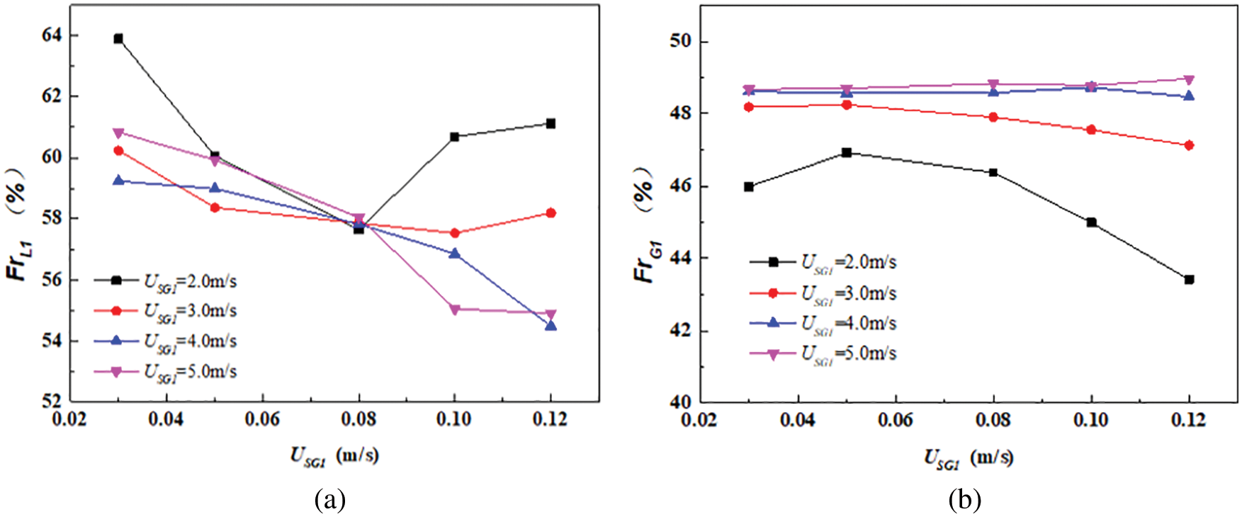
Figure 4: The fraction of liquid and Gas in separator 1 with different liquid velocity
Next, the superficial liquid velocity was selected to analyze the flow pattern in the incoming pipe and risers and the accumulated flow in the two parallel separators under different air-speed conditions. The liquid phase deviation direction was deflected when the superficial gas velocity was between 1.0 and 1.5 m/s. Therefore, these two gas velocity conditions were chosen for analysis.
At the superficial gas velocity of 1.0 m/s, the flow patterns in the three inlet pipes were smooth stratified flows, whereas the flow pattern in the riser was a liquid column–slug-churn flow. Since the cumulative flow curve of the gas-liquid two-phase flow in the separator was stable and smooth, as shown in Fig. 5, the liquid level in the separator increased steadily. The flow pattern of the gas-liquid two-phase flow in the riser connected with separator 2 had the form of a churn flow. This was due to the fact that the gas made the liquid in the riser vibrate violently until the gas lifted the liquid to the top of the riser and entered the separator through a section of the horizontal pipe. A section of the liquid column appeared in the riser connected with separator 1 from bottom to top. The liquid column rose and dropped with the gas-liquid flow in the manifold at the front of the riser. When the liquid phase in riser 2 entered the separator, the pressure at the bottom of the riser decreased, as well as the pressure at the end of the experimental manifold section; therefore, the liquid column in riser 1 decreased. With the increase in the inflow, the pressure at the bottom of the riser increased, as well as the height of the liquid column. During that period, a very small amount of gas passed through the liquid column and went into the separator in the form of bubbles. With the increase in the amount of the gas owing to the continuity of the incoming flow, the gas phase in riser 1 accumulated gradually, and the bubbles increased slightly.
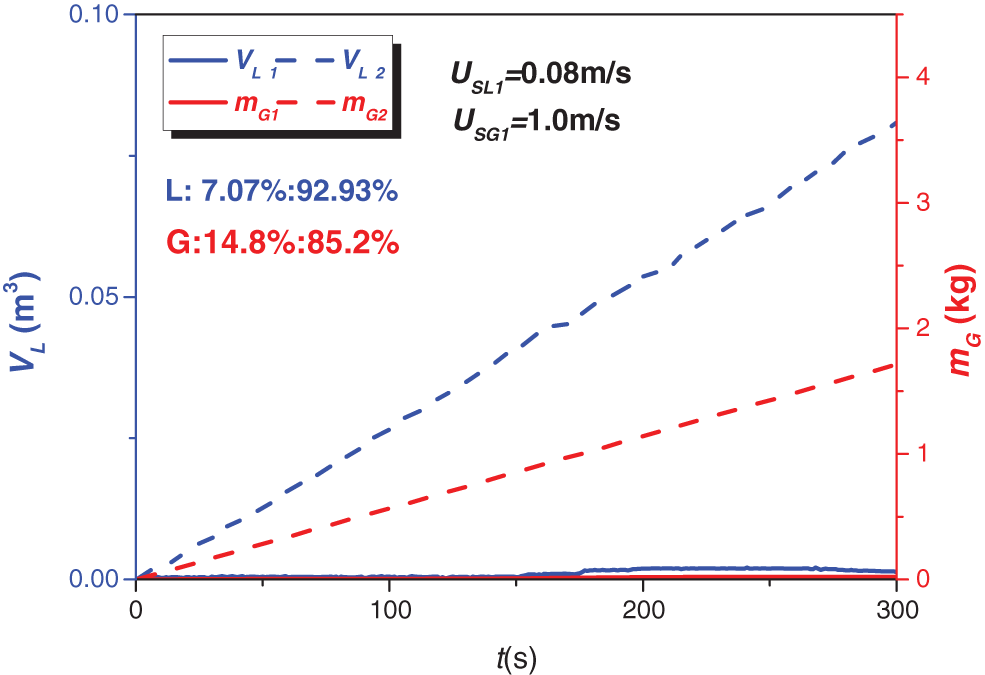
Figure 5: Total flow in the separator with USL = 0.08 m/s and USG = 1.0 m/s
When the pressure at the bottom was higher than the hydrostatic pressure of the liquid column, the liquid phase entered the separator in the form of a liquid plug. After the liquid plug, a short-term churn flow appeared in the riser. The pressure at the bottom of the riser decreased when the gas accumulated at the bottom of the riser was released into the separator, and then the liquid phase in the riser decreased. Therefore, the flow pattern in the riser changed into either a slug flow or a liquid column.
Due to the direct connection with the inlet pipe 2, the liquid volume in riser 1 was large, and the incoming gas volume was small, so the gas phase could easier enter riser 2. Therefore, the pressure accumulation at the bottom of the riser was very slow, and it took a long time to reach the pressure required for the riser to discharge the liquid.
Therefore, the liquid phase moved up and down in the riser in the form of a liquid column for a long time, resulting in a low discharge frequency and decreasing the discharge gas and the liquid phase flow. After the accumulation for a certain period of time, the amount of the discharged gas-liquid flow was negligible compared with the total quantity of the gas and liquid entering the two separators. Therefore, it could be considered that the gas-liquid phases entered separator 2 almost entirely. The gas phase in riser 2 made the liquid phase enter the separator with it, thus forming a churn flow.
At the gas flow rate of 1.5 m/s, the flow patterns in the two risers looked like churn flows. When the liquid phase was more inclined to enter outlet 1 or 2, the degree of bias was 7.10% or 3.71%, respectively, which corresponded to a severe bias range. Compared with the gas velocity of 1.0 m/s, the liquid velocity was still equal to 0.08 m/s, and the gas flow increased. The gas entering the riser 1 could lift the liquid phase towards the separator. Also, there was liquid-phase reflux in the main horizontal pipe connected to the riser, but it did not return to the experimental manifold. The gas and liquid phases flowed into both separators. Since the gas volume was not large enough to support the simultaneous discharge of the liquid from both risers, the liquid flow entered the two parallel separators in an asynchronous or even disconnected manner, which decreased with the increase in the liquid flow.
When the superficial gas velocity increased to 4.0 m/s, there was a nearly-average gas-phase distribution in the two risers, and the liquid phase was more inclined to enter outlet 1 with a bias degree of 7.70%, which was very close to the upper limit of the tolerance displacement range, as shown in Fig. 6b. Under such conditions, the two risers connected to the separator agitated the churn flow. There was no liquid phase backflow in the horizontal main pipe at the bottom of the risers. The liquid could be lifted entirely into risers by the gas and enter the separators through the short horizontal pipe, which was due to the high superficial gas velocity. The gas and liquid in the risers were the oscillating liquid film. With the rapid increase in the gas phase, the liquid phase from the two horizontal branch pipes to the separator was out of synchronization, but there was no flow interruption. In addition, with the increase in the superficial gas velocity, the flow pattern in the risers was also the churn-churn flow, whereas the liquid into the two separators gradually became continuous and synchronized.
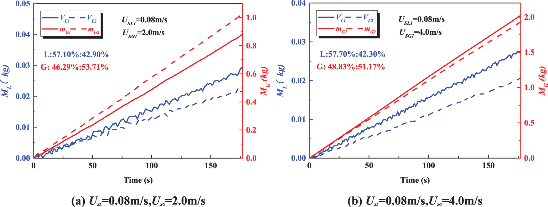
Figure 6: Total flow in the separator
3.3 Asymmetric Resistance Experiment of Outlet Pipeline
The liquid-phase outlet pipeline remain unchanged, while the gas-phase outlet pipeline has an improved structure compared to the original design, as shown in Fig. 7. Namely, a bypass pipeline was added to the original pipeline, and orifice plates with different diameters were inserted between the flanges (i.e., valve 1 in Fig. 7) to increase the resistance of the gas-phase outlet pipeline. In this experiment, valve 1 was opened, and valve 2 was closed to ensure that the resistance of the gas-phase outlet pipeline was lower than that of the gas-phase outlet pipeline of the other separator.
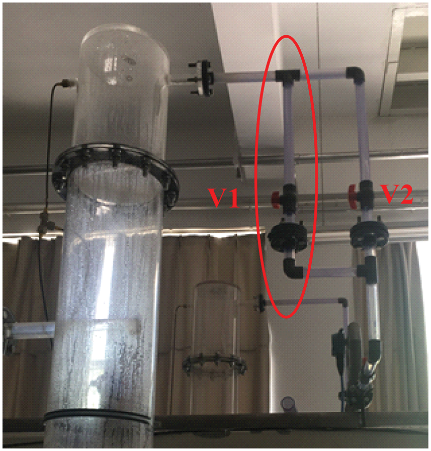
Figure 7: Improvement of gas phase outlet pipeline of separator
The experiment was conducted under the condition of the original gas-liquid velocity combination. The experimental results were as follows.
As shown in Fig. 8, after the orifice plate was installed, the gas phase was unevenly distributed. With the increase in the superficial gas velocity, the uneven distribution degree gradually stabilized at about 25%. This was because the gas phase outlet throttling caused the increase in the pressure in the separator, so the gas tended to enter separator 2.

Figure 8: The fraction of the gas flow with orifice plate on gas outlet pipe
When investigating uneven gas-liquid distribution under a symmetrical condition, the results showed that the gas-liquid two-phase flow at the gas-liquid velocity higher than 1.5 m/s was redistributed through the manifold structure. This allowed the gas to be evenly distributed, and the liquid tended to enter separator 1, so the degree of uneven distribution drastically increased. Based on the previous research on the gas-liquid two-phase flow in the impacting T-junction of a horizontal riser, adding an orifice plate can change the bias degree of the gas-liquid two-phase flow to a certain extent. Under this consideration, the experiment under asymmetric conditions was performed. The orifice plate was added to the gas outlet pipe of separator 1 to increase the resistance. The superficial velocities of the liquid and gas in this experiment were assumed to be the same as that in the experiment under the symmetrical condition. The experimental results are shown in Fig. 9.
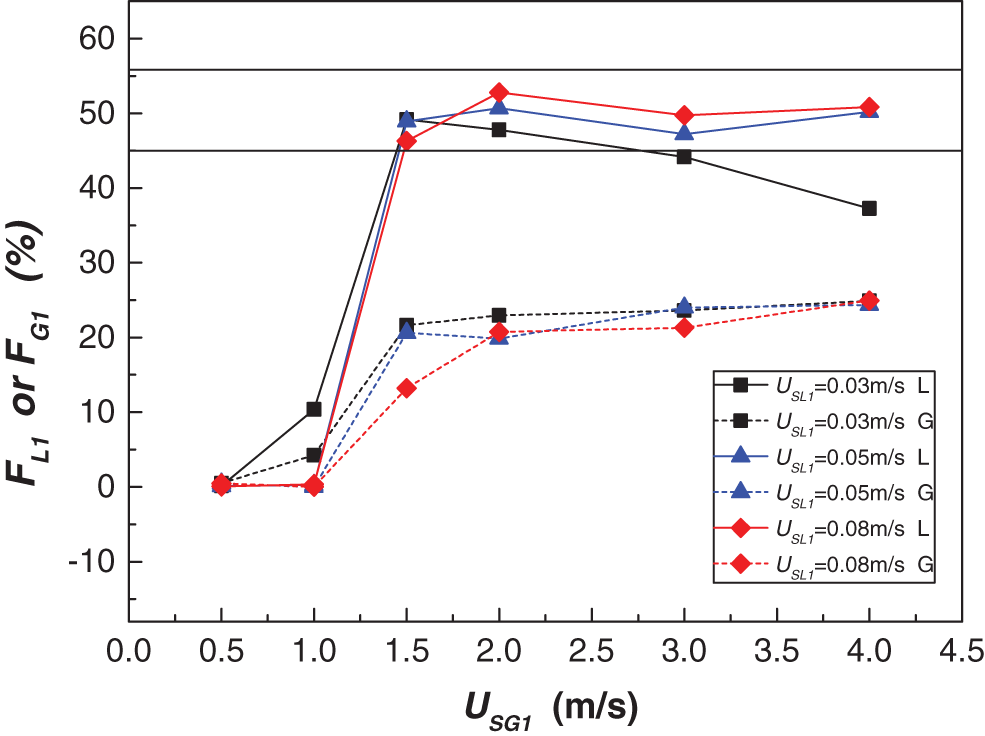
Figure 9: The fraction of the two phase flow at outlet 1with orifice plate on gas outlet 1
After installing the orifice plate, according to the principle of minimum energy consumption, the increase in the resistance of the gas-phase outlet pipeline caused the gas-liquid two-phase flow to even more incline to enter the pipeline with lower resistance. Therefore, the distribution ratio of the gas-liquid two-phase flow in separator 1 was inferior to that of the pipeline without the orifice plate under the same operating conditions.
The phase distribution regular pattern of the gas-liquid two-phase flow through the manifold structure in the two separators was roughly the same as that of the symmetrical-resistance pipeline without the orifice plate.
The proportion of liquid entering separator 1 increased dramatically from extremely low (close to zero) to approximately 0.5, while the superficial velocity of gas increased. However, the only difference was that the gas velocity decreased from 1.0 to 0.5 m/s when the liquid column–slug flow occurred in the riser. According to the comparative analysis of the splitting degree of a two-phase flow in the symmetric-resistance pipeline and the flow pattern in two risers, only when there was the liquid column–slug-churn flow in the risers, the gas-liquid two-phase flow almost entered the side of the churn flow. Therefore, the fraction of the gas-liquid two-phase flow entering separator 1 was close to zero. The flow pattern in the riser connected to separator 1 was a liquid column–slug-churn flow, while the gas velocity was 0.5 m/s, or the gas velocity was 1.0 m/s, and the liquid velocity was 0.08 m/s or 1.0 m/s.
The fraction of the gas in separator 1 increased with the gas velocity when there was an orifice in the outlet gas pipe after the separator. However, due to the change in the gas pipeline outlet resistance, the uneven splitting of gas was always in a strongly biased region.
If the requirements for the gas processing capacity of a separator are not considered, then only the phase distribution of liquid is concerned, and the resistance of the outlet pipeline of the atmospheric phase (e.g., orifice plate) is added. This can effectively adjust the distribution proportion of the liquid phase in two separators so that the liquid level in two parallel separators is stable and the treatment capacity stays almost unchanged.
Based on the previous research, when the shunt component is an impacting T-junction, whether to connect the risers’ section behind the shunt component has been the main influencing factor of the uneven phase distribution in a parallel separator. Risers denote the main cause of the uneven distribution of a gas-liquid two-phase flow. However, in the production process of offshore oil and gas, risers are necessary and essential. The gas-liquid two-phase flow in risers has a strong influence on the downstream pipelines and equipment.
During the air-water two-phase flow experiment, three types of flow pattern combinations were observed in the risers: a liquid column–slug-churn, a slug–churn-churn, and a churn-churn flow pattern combinations, as shown in Fig. 10.
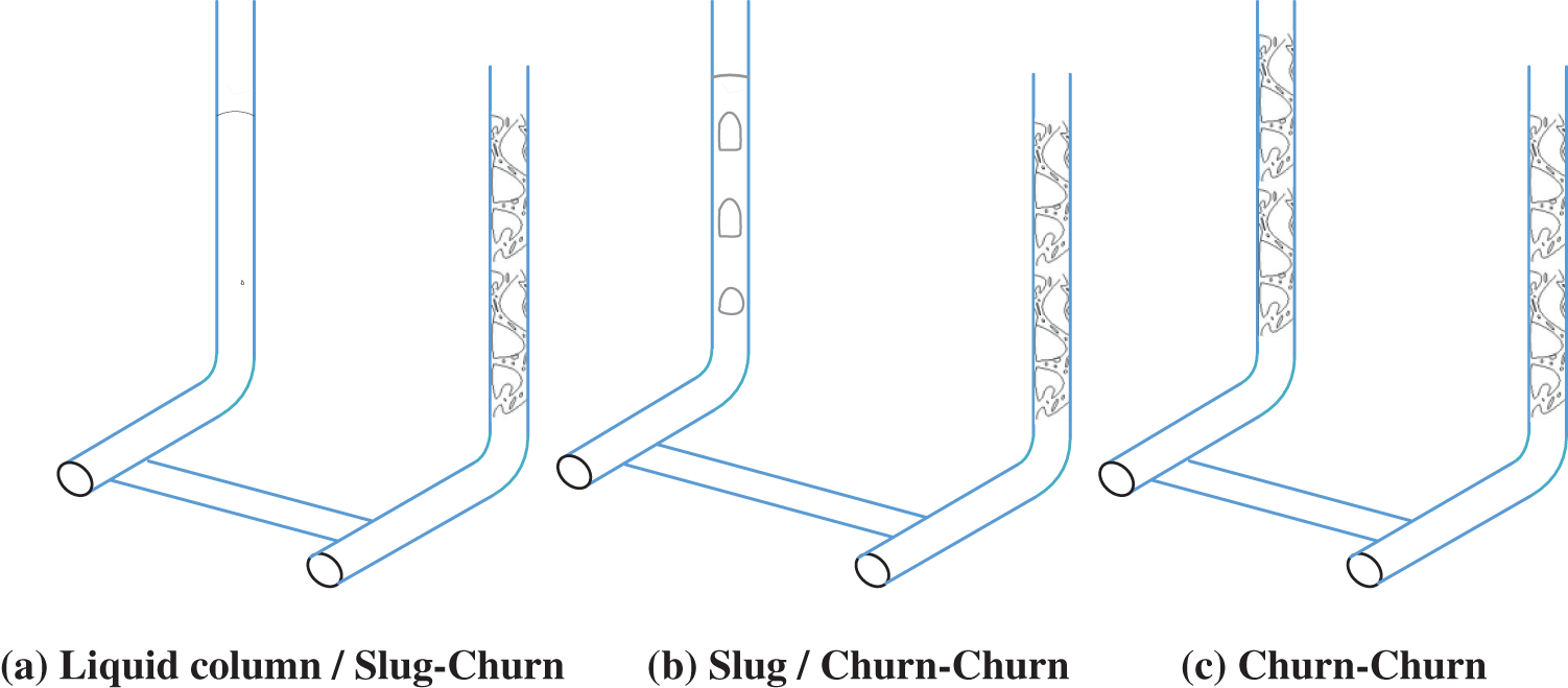
Figure 10: Flow pattern of risers
The first type of flow pattern in risers was a liquid column–slug-churn flow pattern, as shown in Fig. 10a. There was a liquid column in one of the pipes, and the other one was churn. This phenomenon generally occurs under the condition of low superficial gas velocity. In this experiment, one side of the churn was always the churn, and the liquid column on the other side moved up and down and increased continuously. Because of the liquid column in the riser, a very small amount of gas passed through the liquid column in the form of bubbles and entered the separator. With the increase in the liquid column, the pressure at the bottom of the riser also increased. When the pressure was higher than the hydrostatic pressure of the liquid column, the liquid began to discharge from the riser, and the liquid amount accumulated at the bottom of the riser decreased gradually. When it was reduced to a certain extent, the gas flows into the riser, and the liquid was accelerated to discharge under the pressure difference between the riser and the separator outlet. The pressure at the bottom of the riser was further reduced, and the gas phase accumulated in the upstream pipeline entered the riser at a very high speed. At that point, the flow pattern in the riser was churn, and under such a flow pattern, the formation of strong slugs was very slow.
As shown in Fig. 10b, in some periods of time, the gas-liquid flow pattern in one of the risers showed the slug flow, and the other behaved as a churn flow. The difference between the air distributions in the two risers resulted in different liquid levels, which caused the liquid phase in the separator connected with a churn flow to flow out continuously, while the liquid phase in the other separator was cut off. This type of unsteady state was changed to the churn-churn flow pattern. The transformation process was similar to that of the liquid column–slug-churn flow pattern, but the liquid plug was smaller, the discharge frequency was higher, and the churn flow lasted longer.
According to the results in Fig. 10c, the gas-liquid flow pattern in the two risers was the churn-churn flow pattern, which generally occurred under the condition of a high superficial gas velocity. The gas and liquid in the riser were the oscillating liquid films. The liquid phase recovery at the inlet of the separator was not synchronous, and the liquid phase was cut off; also, the continuous liquid extraction and flow were observed in the separator.
The ranges of the gas-liquid velocity flow patterns for inlet 1 and riser at three mass flow rates are shown in Fig. 11.
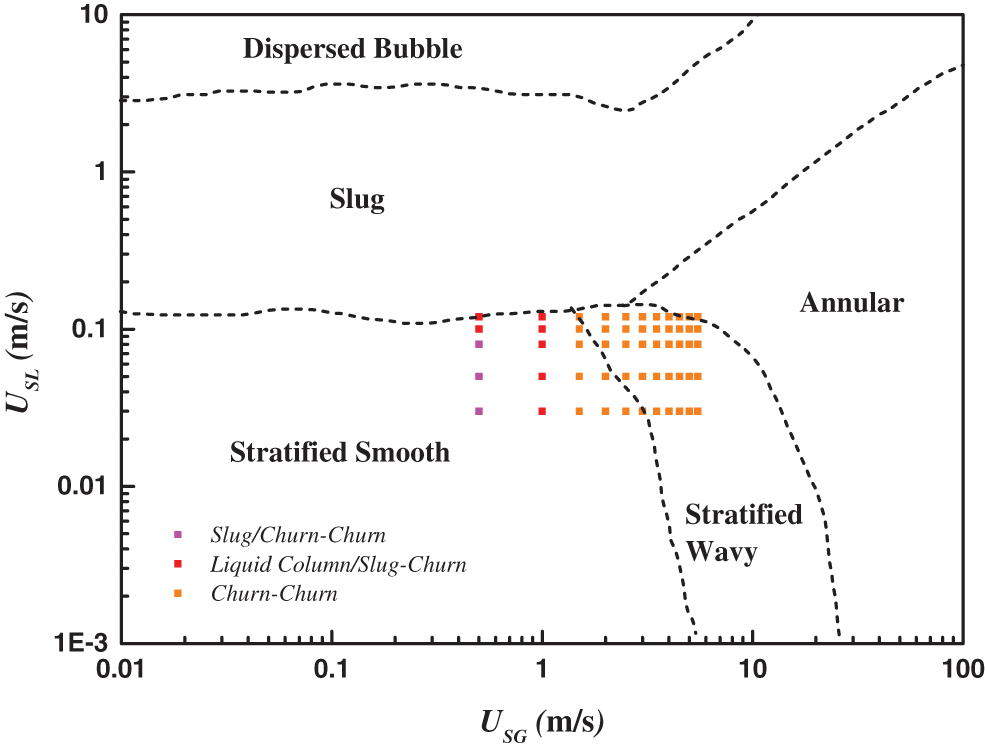
Figure 11: Flow velocity and riser flow pattern
The flow pattern of the incoming pipe was shown to be basically stratified or wavy flow. A small number of slugs were observed occasionally in the pipeline. Since the number and the length of slugs were small, they had no effect on the overall experimental results, so the flow pattern in the risers was not affected. Therefore, it could be concluded that the flow patterns in the inflow pipe were both stratified smooth or stratified wavy. According to the results in Figs. 3 and 11, the extreme case occurred when the flow pattern of the inlet pipe was stratified smooth.
This study aims to analyze the gas-liquid two-phase flow splitting in a specific manifold. Based on the obtained results, the following conclusions can be drawn:
1) Under the condition of a low gas velocity, the gas-liquid two-phase flow is strongly biased, but the direction of the gas-liquid two-phase flow remains unchanged. In addition, almost the entire gas-liquid two-phase flow can enter one of the separators.
2) At the gas flow rate higher than 1.5 m/s, the deviation degree of the gas-liquid two-phase flow decreases with the gas flow rate, and the liquid phase approaches the upper limit of the tolerated range of the flow deviation. The deviation degree of the gas-phase flow decreases with the flow rate.
3) The asymmetric resistance of the gas-phase outlet pipeline can change the phase distribution ratio of the gas-liquid two-phase flow in the separator and effectively improve the bias flow.
4) The liquid column–slug-churn flow appears when the gas velocity is low, and it is accompanied by the extreme bias flow, which needs to be avoided in actual production. However, the slug–churn-churn flow emerges under the medium and low-speed conditions, and the bias flow is not stable and cannot be accurately predicted. Finally, the churn-churn flow occurs mostly at high gas velocities, when the gas and liquid in the riser are oscillating liquid films.
Funding Statement: This work was supported by the National Science and Technology Major Project of China (No. 2016ZX05028-004-003).
Conflicts of Interest: The authors declare that they have no conflicts of interest to report the presented study.
References
1. Shen, D., Gui, C., Xia, J., Xue, S. (2020). Experimental analysis of the performances of unit refrigeration systemsbased on parallel compressors with consideration of the volumetric and isentropic efficiency. Fluid Dynamics & Materials Processing, 16(3), 489–500. DOI 10.32604/fdmp.2020.08969. [Google Scholar] [CrossRef]
2. Oranje, L. (1973). Condensate behavior in gas pipelines is predictable. Oil and Gas Journal, 7(2), 39–44. [Google Scholar]
3. Azzopardi, B. J. (1994). The split of vertical annular flow at a large diameter T-junction. International Journal of Multiphase Flow, 20, 1071–1083. DOI 10.1016/0301-9322(94)90055-8. [Google Scholar] [CrossRef]
4. Wren, E., Azzopardi, B. J. (2004). Affecting the phase split at a large diameter T-junction by using baffles. Experimental Thermal & Fluid Science, 28(8), 835–841. DOI 10.1016/j.expthermflusci.2003.12.017. [Google Scholar] [CrossRef]
5. Yin, P., Cao, X., Li, Y., Yang, W., Bian, J. (2018). Experimental and numerical investigation on slug initiation and initial development behavior in hilly-terrain pipeline at a low superficial liquid velocity. International Journal of Multiphase Flow, 101, 85–96. DOI 10.1016/j.ijmultiphaseflow.2018.01.004. [Google Scholar] [CrossRef]
6. Liu, M., Zhang, X., Wang, D. (2021). Experimental study on the flow characteristics of a plate with a mechanically choked orifice. Fluid Dynamics & Materials Processing, 17(1), 97–107. DOI 10.32604/fdmp.2021.011292. [Google Scholar] [CrossRef]
7. Ma, L., He, L., Luo, X., Mi, X. (2021). Numerical simulation and experimental analysis of the influence of asymmetric pressure conditions on the splitting of a gas-liquid two-phase flow at a T-junction. Fluid Dynamics & Materials Processing, 17(5), 959–970. DOI 10.32604/fdmp.2021.016710. [Google Scholar] [CrossRef]
8. Ma, L., He, L., Luo, X. (2020). Experimental investigation of gas-liquid two-phase splitting in parallel pipelines with risers. Chemical Engineering Research and Design, 161, 159–167. DOI 10.1016/j.cherd.2020.07.009. [Google Scholar] [CrossRef]
9. Azzopardi, B. J., Purvis, A., Govan, A. H. (1987). Annular two-phaseflow split at an impacting T. International Journal of Multiphase Flow, 13(5), 605–614. DOI 10.1016/0301-9322(87)90038-3. [Google Scholar] [CrossRef]
10. Azzopardii, B. J., Purvis, A., Govan, A. H. (1988). Flow split of churnflow at a vertical impacting T. International Journal of Engineering Fluid Mechanics, 1, 320–329. [Google Scholar]
11. Taitel, Y., Pustylnik, L., Tshuva, M., Barnea, D. (2003). Flow distribution of gas and liquid in parallel pipes. International Journal of Multiphase Flow, 29(7), 1193–1202. DOI 10.1016/S0301-9322(03)00067-3. [Google Scholar] [CrossRef]
12. Watanabe, M., Katsuta, M., Nagata, K., Sakuma, K. (1995). General characteristics of two-phase flow distribution in a multipass tube. Heat Transfer-Japanese Research, 24(1), 32–44. [Google Scholar]
13. Horiki, S., Osakabe, M. (2000). Water flow distribution in horizontal protruding-typeheader contaminated with bubbles. Journal of the Tokyo University of Mercantile Marine Natural Sciences, 51(5), 111–118. [Google Scholar]
14. Lee, J. K., Lee, S. Y. (2004). Distribution of two-phase annular flow at header–channel junctions. Experimental Thermal & Fluid Science, 28(2–3), 217–222. DOI 10.1016/S0894-1777(03)00042-6. [Google Scholar] [CrossRef]
15. Lee, J. K. (2009). Two-phase flow behavior inside a header connected to multiple parallel channels. Experimental Thermal and Fluid Science, 33(2), 195–202. DOI 10.1016/j.expthermflusci.2008.03.009. [Google Scholar] [CrossRef]
16. Yin, P., Zhang, P., Cao, X., Li, X., Bian, J. (2022). Effect of SDBS surfactant on gas–liquid flow pattern and pressure drop in upward-inclined pipelines. Experimental Thermal & Fluid Science, 130, 110–507. DOI 10.1016/j.expthermflusci.2021.110507. [Google Scholar] [CrossRef]
 | This work is licensed under a Creative Commons Attribution 4.0 International License, which permits unrestricted use, distribution, and reproduction in any medium, provided the original work is properly cited. |