| Fluid Dynamics & Materials Processing |
DOI: 10.32604/fdmp.2023.021590
ARTICLE
The Effects of Thermal Radiation and Viscous Dissipation on the Stagnation Point Flow of a Micropolar Fluid over a Permeable Stretching Sheet in the Presence of Porous Dissipation
1Faculty of Informatics and Computing, University Sultan Zainal Abidin (Kampus Gong Badak), Kuala Terengganu, Terengganu, Malaysia
2Department of Mathematics, College of Education for Pure Sciences, University of Kerbala, Kerbala, Iraq
3Department of Mathematics, Division of Science and Technology, University of Education, Lahore, Pakistan
*Corresponding Author: Abid Hussanan. Email: abid.hussanan@ue.edu.pk
Received: 22 January 2022; Accepted: 07 April 2022
Abstract: In this paper, the effects of thermal radiation and viscous dissipation on the stagnation–point flow of a micropolar fluid over a permeable stretching sheet with suction and injection are analyzed and discussed. A suitable similarity transformation is used to convert the governing nonlinear partial differential equations into a system of nonlinear ordinary differential equations, which are then solved numerically by a fourth–order Runge–Kutta method. It is found that the linear fluid velocity decreases with the enhancement of the porosity, boundary, and suction parameters. Conversely, it increases with the micropolar and injection parameters. The angular velocity grows with the boundary, porosity, and suction parameters, whereas it is reduced if the micropolar and injection parameters become larger. It is concluded that the thermal boundary layer extension increases with the injection parameter and decreases with the suction parameter.
Keywords: Micropolar fluid; viscous dissipation; stagnation point; stretching sheet; porous media; thermal radiation
Micropolar fluids are solutions based on microstructures. They occur in a non–symmetrical stress tensor class of fluid called polar liquids. The developed classical fluid Navier–Stokes pattern will classify ordinary liquids in this circumstance. Physically, solid fluids have arbitrarily guided particle suspension in a dense medium where fluid particulate deformations can be ignored and can reflect micropolitan fluids themselves. More recently, the study of the movement and heat transmission of micropolar liquids in voids has been of considerable and ever-growing concern, as Newtonian liquids cannot efficaciously explain the suspended particle liquid characteristics. Compared to other fluids, non–Newtonian liquids composed of moronic particles or short, stiff components, fluid suspension, polymer liquids, and more can be defined as micropolar fluids. A micro–rotation trajectory and a revolution function are added to the micropolar liquid pattern with the traditional velocity region to analyze the micro–rotation kinematics.
The non–Newtonian behavior of certain liquids includes colloidal liquids, liquefied quartzes, deformable living organism plasma, iron solutions, clouds of smoke, suspension, liquids with polymer additives, and slurry may also have successfully been identified in theory as micropolar fluids. Eringen [1,2] is worth investigating, as their micropolar fluids model is well–equilibrated. In the first place, the classical Navier Stokes model is well known and broadly generalized, addressing a more significant number of manifestations than the classical one in both theory and application. The fluid and heat transfer flow can be estimated with the necessary boundary conditions employing the mass, momentum, and energy conservation equation. For more complicated industrial applications, a thorough inquiry of liquid motion and heat transference structures is essentially basic geometry, including regarding the buoyancy–driven space, which is an essential prerequisite to assessing efficient products. Many engineering applications, such as ventilation and heating, energy transport, electronic packaging, natural convection of cavities, and cooling in nuclear reactors, are important. Hussanan et al. [3] exhibited certain initiation trials with a micropolar nanofluid model moving above a shrinking/stretching pane with suction/injection parameters. Mishra et al. [4] discussed micropolar fluid flow and heat transfer over a shrinking sheet via the Runge–Kutta scheme, followed by the shooting technique. Bhat et al. [5] performed experiments on the laminar movement of micropolar liquid with a porous and a non–porous disk by applying the Keller–box method. Shehzad et al. [6] examined the micropolar liquid motion with titanium and ferromagnetic alloy due to viscous dissipation and moving over a porous sheet. Ali et al. [7] presented a gravity modulation with a non–Newtonian micropolar fluid under the consequences of thermal radiation, suction/injection, magnetic fields, and mixed convection. Siddiqa et al. [8] contemplated that micropolar fluid of heat transfer and thermal radiation flow is driven by a finite vertical plate. The second-order Gauge Uzawa scheme for the governing equations of an incompressible micropolar fluid flow is introduced by Slayi et al. [9]. Siddiqui et al. [10] investigated heat and mass traansfer flow of micropolar fluid in a rectangular channel with permeable slits. Other prominent works on the micropolar fluid include those by [11–18].
Stagnation point flow is a significant factor; interactions among the liquid motion and rigid constructions have been attributed to the stagnation point’s motion properties. It is essential in current applications to determine the physical parameters’ variance across the flow environment. The maximum heat transfer and high pressure in the stagnation motion, followed by a velocity decrease, occur all over the flow region. Owing to its abundant submission in manufacturing, for example, within wire design, in the prominence of polymer in a melting phase, fibers, and plastic film processing, attention is focused on the heat transport dynamics in a stagnation–point flow of micropolar fluid above a stretch shallow. Academic and experimental researchers are very interested in focus heat transference and fluid movement within the porous medium because of their use in many fields of engineering like surface catalysis of chemical reactions, groundwater movement, nuclear waste disposal, oil and gas production, reliable matrix heat exchanges, geothermal energy extraction, adsorption, regenerative heat exchange, and current padding ventilation of porous objects, etc. Nazar et al. [19] provided a numerical method of the stagnation point movement with micropolar liquid moving over a stretching sheet using the Keller–Box method.
Abbas et al. [20] studied the stagnation point flow of micropolar nanofluid in a porous media. Soomro et al. [21] inspected the numerical solution of stagnation point boundary layer flow towards a stretching surface by using the finite difference method. Their results specified that, due to the growth in Brownian motion and thermophoresis, the Nusselt number declines although the Sherwood number increases. The boundary layer flow with the combined effects of thermal radiation and magnetohydrodynamics (MHD) over a nonlinear stretching surface under the Casson nanofluid and stagnation point region was presented by Besthapu et al. [22]. Khan et al. [23] inspected the two-dimensional boundary layer movement of Carreau and Cattaneo–Christov liquid with stagnation point movement through a stretching/shrinking cylinder. Abbas et al. [24] also discussed the three-dimensional stagnation point motion with hybrid nanofluid associated with slip conditions. Recently, Abbasi et al. [25] reported the numerical solution of the incompressible Maxwell nanofluid through non–orthogonal stagnation point flow moving over a stretching cylinder. Arani et al. [26] analyzed the stagnation point movement with nanoparticles through a porous sheet using the Runge–Kutta Fehlberg method. The microorganisms analysis for Williamson nanofluid flow past a horizontal linearly stretching/shrinking sheet under the stagnation point region and similarity transformations were studied by Muthtamilselvan et al. [27]. Renuka et al. [28] examined unsteady stagnation point flow and the heat transfer of nanofluid towards a flat plate with Brownian diffusion and thermophoresis. Furthermore, stagnation–point flow and heat transfer over stretchable plates and cylinders with an oncoming flow were all examined by Turkyilmazoglu [29]. Some observations on stagnation point flow are recently addressed for numerous hypotheses by [30–38].
The influence of viscous dissipation and thermal radioactivity composes a significant property in the fluid’s temperature distribution, which causes the fluid’s internal friction. Fluid viscosity transforms dynamic energy into updraft energy due to the drive of liquid units. The viscosity property leads to the reversible process, and this phenomenon is known as viscous dissipation. In manufacturing industries such as food manufacturing, cooling nuclear reactors, oil discovery, bioengineering, and others, this impact has substantially greater importance. Moreover, Abd El-Aziz [39] reported the impact of viscous dissipation and mixed convection flow over the heat transfer mechanisms with micropolar fluid. Mixed Convection radiative with viscous dissipation and stagnation point flow past over a porous stretching/shrinking sheet has been described by Pal et al. [40]. Fatunmbi et al. [41] numerically investigated the effects of thermal radiation and viscous dissipation over a permeable stretching plate in a porous medium through the 4th order Runge–Kutta integration procedure. A concise analysis of the literature on the influence of viscous dissipation and thermal radioactivity can be found in several relevant references [42–52]. Most recently, Mishra et al. [53] investigated thermal radioactivity, viscous dissipation, and Joule heating with the nanofluid movement in the occurrence of a porous sheet. Aziz et al. [54] studied the thermal radiation and viscous dissipation with Powell–Eyring hybrid nanofluid through the Keller–Box finite difference method.
Heat transfer flow over a stretching sheet has several engineering applications, such as aerodynamic extrusion of polymer, petroleum processing, efficiency improvement of paints and aeration, chemical particle beds, rubber sheets, glass manufacturing, transpiration cooling, and plastic shaping and paper production. Since the pioneering work on the stretching sheet, several studies have been carried out on the various aspects of heat transfer in different fluid flows. Yusuf et al. [55] studied three-dimensional hybrid–nanofluid flow over a stretching sheet in a porous medium. The frictional heating properties of Casson nanofluid over a stretching sheet with Brinkmann Forcheiemerr porous medium are addressed by Sharanappa et al. [56]. Kausar et al. [57] reported Darcy–Brinkman fluid flow over a stretching sheet using the Runge–Kutta BVP4C scheme with shooting techniques. Irfan et al. [58] extended the pioneering work of porous media and stretching sheets with stream flow and variable fluid characteristics. Goud [59] recently analyzed the influence of heat generation/absorption through a permeable stretching plate with suction/injection.
This current research aims to investigate 2–D thermal radiation and viscous dissipation on stagnation point flow towards a permeable stretching sheet in the presence of porous dissipation. We have tinted the impacts of suction/injection to examine the flow behaviour under the assumption of stagnation point flow over a permeable stretching sheet. We also thought about the influences of the porosity parameter. The micropolar fluid flow has been in steady and laminar flow cases. The dimensionless structure has access to flow by the Runge–Kutta procedure of the 4th order of the numerical scheme. Graphs and tables indicate the spatial dimension parameters used in the flow assumptions. The skin friction and heat transfer rate (Nusselt number) were explored at the surface. Some significant findings may contribute to further innovations in engineering and research regarding these concepts and this specific topic.
The steady force convection stagnation point flow of a micropolar fluid over a non–isothermal stretching sheet is considered. The
The corresponding boundary conditions are (see, Turkyilmazoglu [60])
where
Here
By the Rosseland approximation, we have
and thus Eqs. (4) and (6) leads
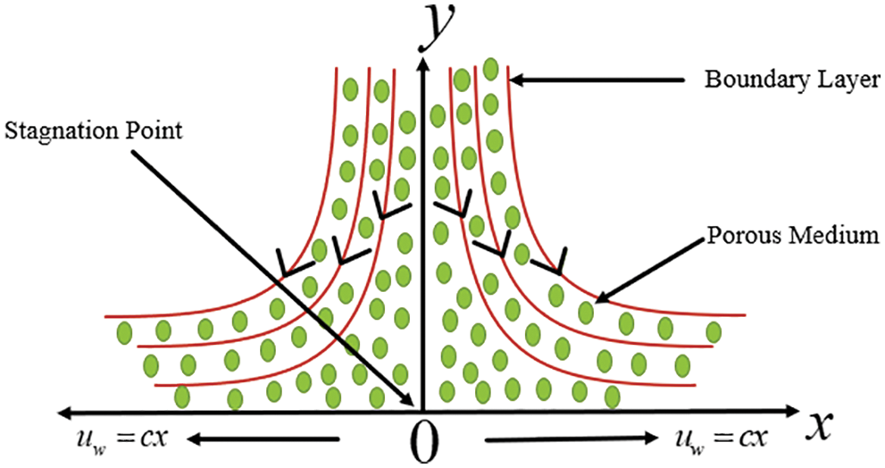
Figure 1: Physical interpretation of stagnation point flow
The following similarity transformations are introduced to resolve the partial differential equations
Here
Subject to the boundary conditions, (5) which become
In the above equations, the prime signifies the derivative with respect to
Note that the effective Prandtl number
The skin friction coefficients
In the dimensionless form, the above expression is written as
where
The Runge–Kutta 4th order approach is used to resolve the nonlinear ordinary differential Eqs. (9)–(11) associated boundary conditions (12). The nonlinear ordinary differential equations are in third-order linear velocity, second in angular momentum, and temperature reduced in a simultaneous ordinary equation system. We need two other skipped initial conditions to resolve this scheme by Runge–Kutta 4th order process. But, the values of
This article studied two–dimensional force convection micropolar boundary layer stagnation point flow over a stretching sheet embedded in a porous medium viscous dissipation. We evaluate the range of linear momentum parameters, angular momentum, and thermal boundary layers in simulated results, the nonlinear governing Eqs. (9)–(11) associated boundary conditions (12) are solved with the 4th order Runge–Kutta method. The computational approximation has been carried out. The steady flow is obtainable with different parameter values like constant ratio parameter
The set of parameters turned out to be the most fascinating as either a function of synchronized distance, physical profiles, and behavior are observed. The linear velocity profiles
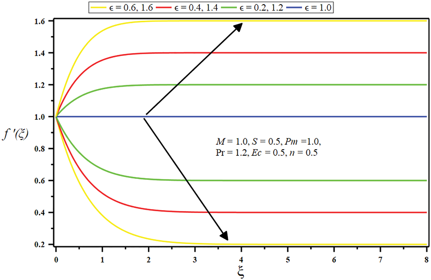
Figure 2: Influence of constant ratio parameter
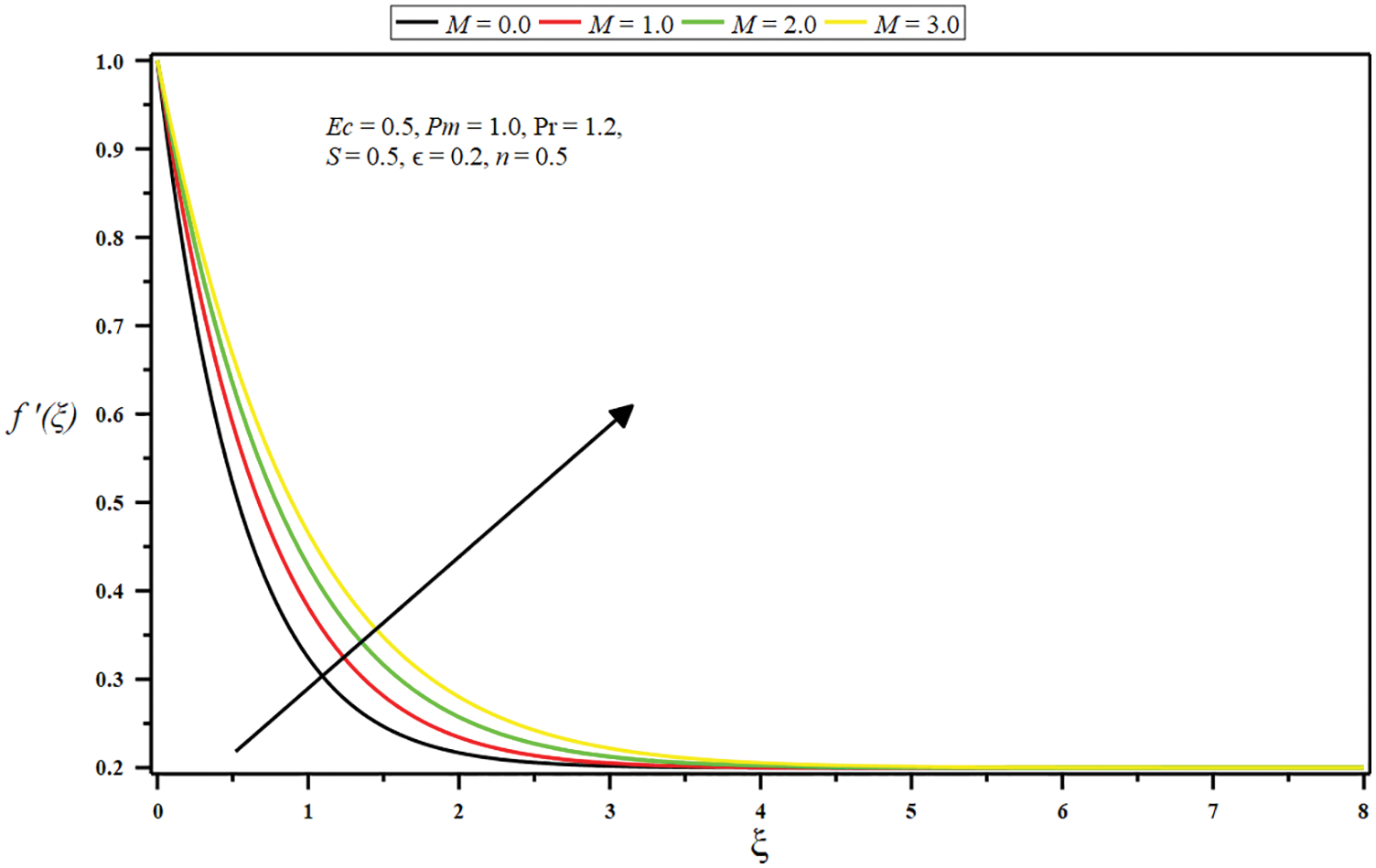
Figure 3: Influence of micropolar parameter
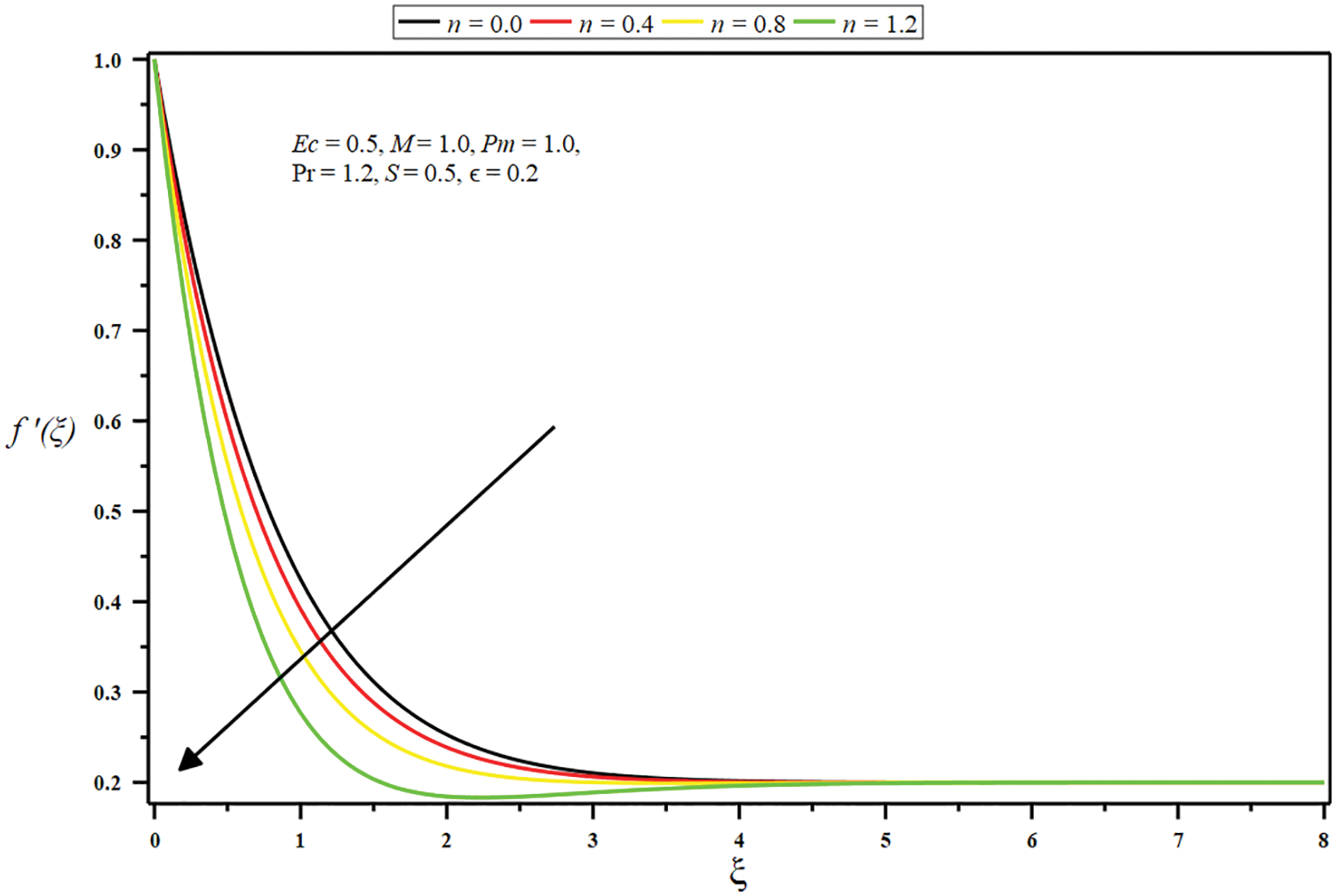
Figure 4: Influence of boundary parameter
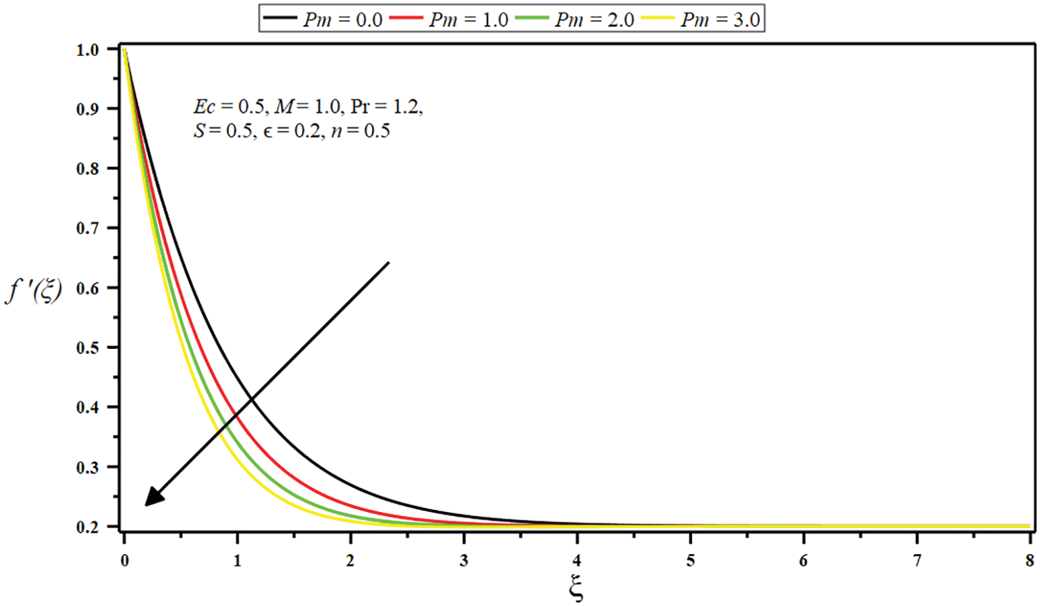
Figure 5: Influence of porosity parameter
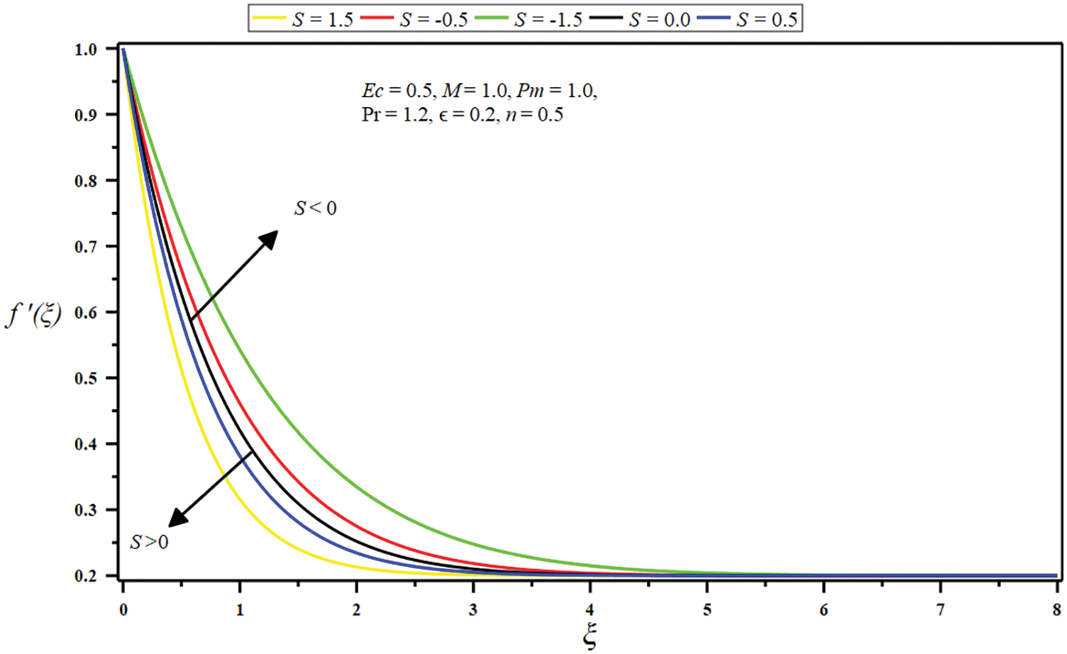
Figure 6: Influence of suction/injection parameter
Figs. 7–11 demonstrate the impression of some governing parameters on the angular velocity
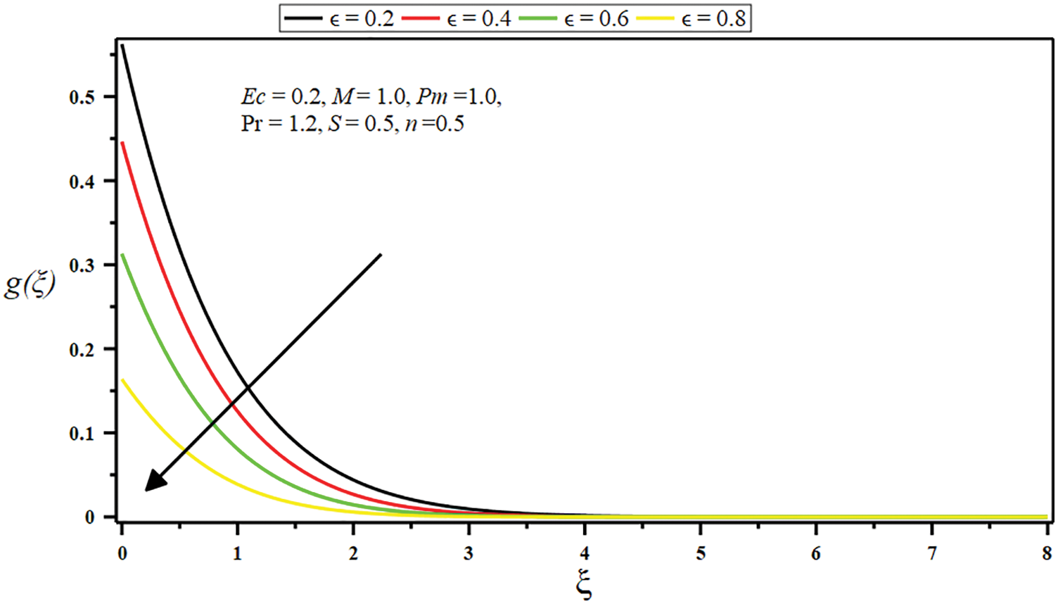
Figure 7: Influence of constant ratio parameter
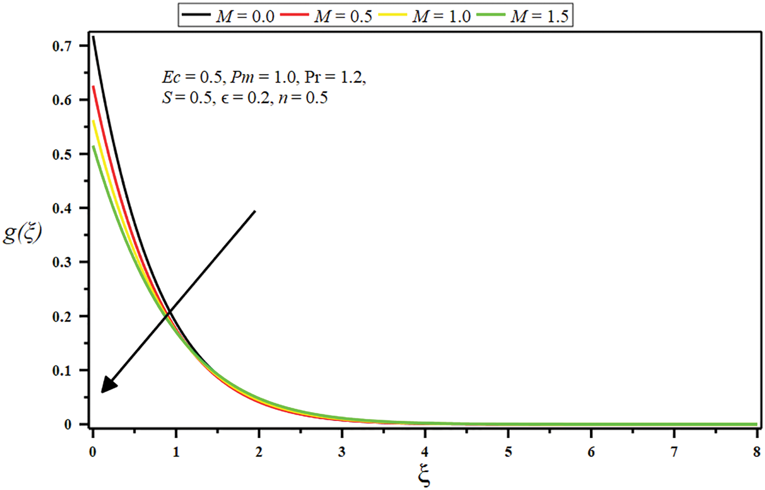
Figure 8: Influence of micropolar parameter
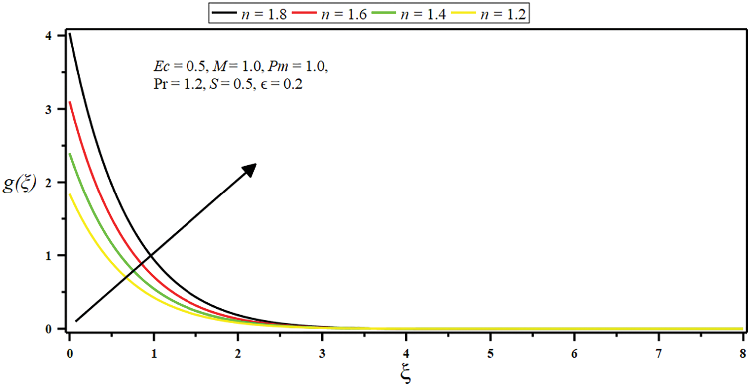
Figure 9: Influence of boundary parameter
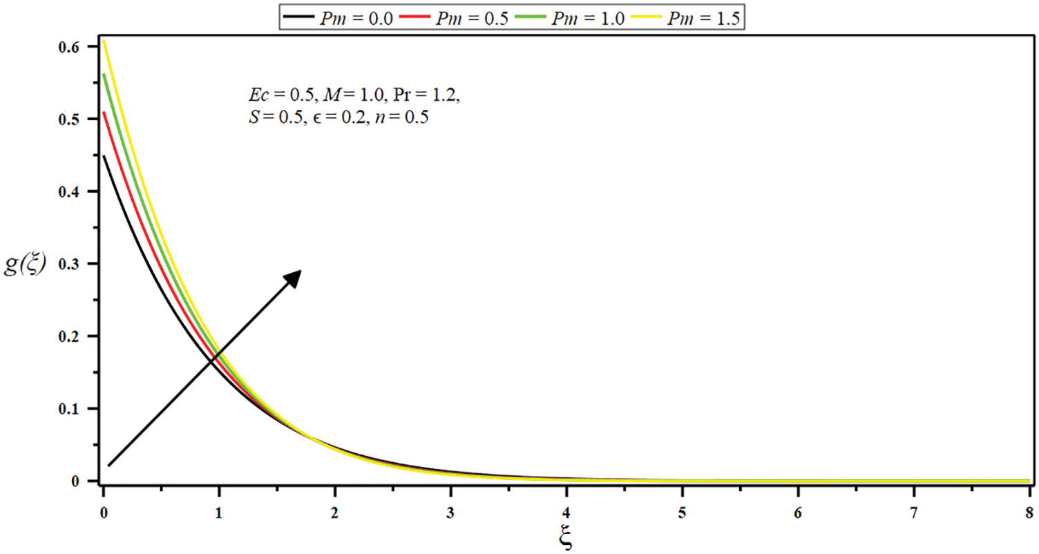
Figure 10: Influence of porosity parameter
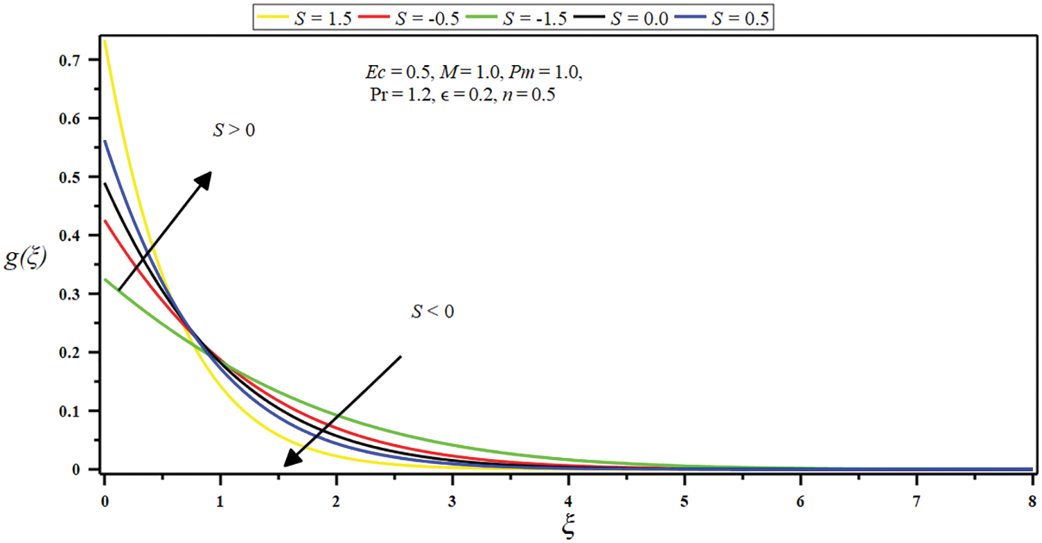
Figure 11: Influence of suction/injection parameter
The boundary layer is also reduced by enhancing the values of
Figs. 12–16 demonstrate the impact of the several governing parameters on stagnation point flow for the dimensionless temperature
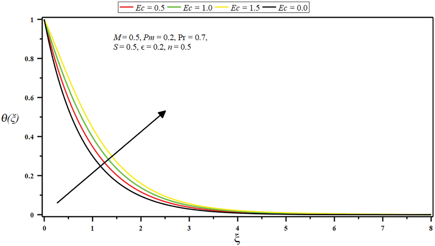
Figure 12: Impact of Eckert number
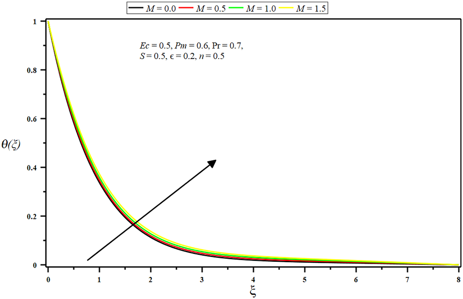
Figure 13: Impact of micropolar parameter
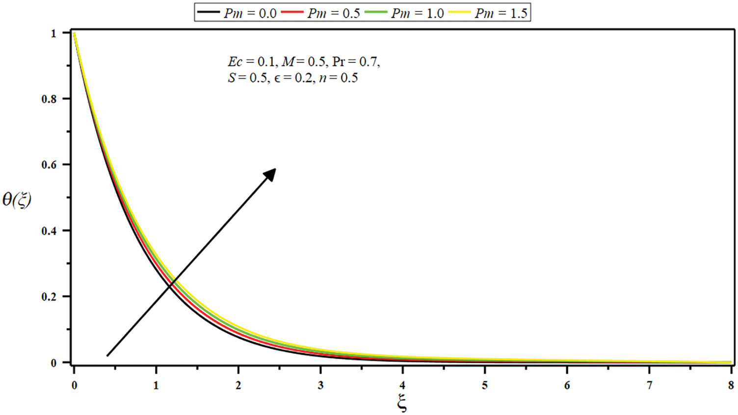
Figure 14: Impact of porosity parameter
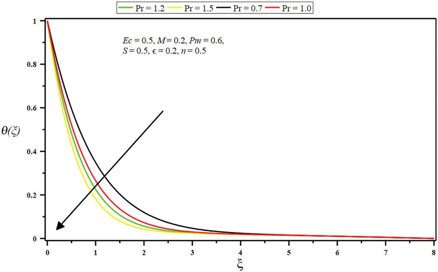
Figure 15: Impact of Prandtl number
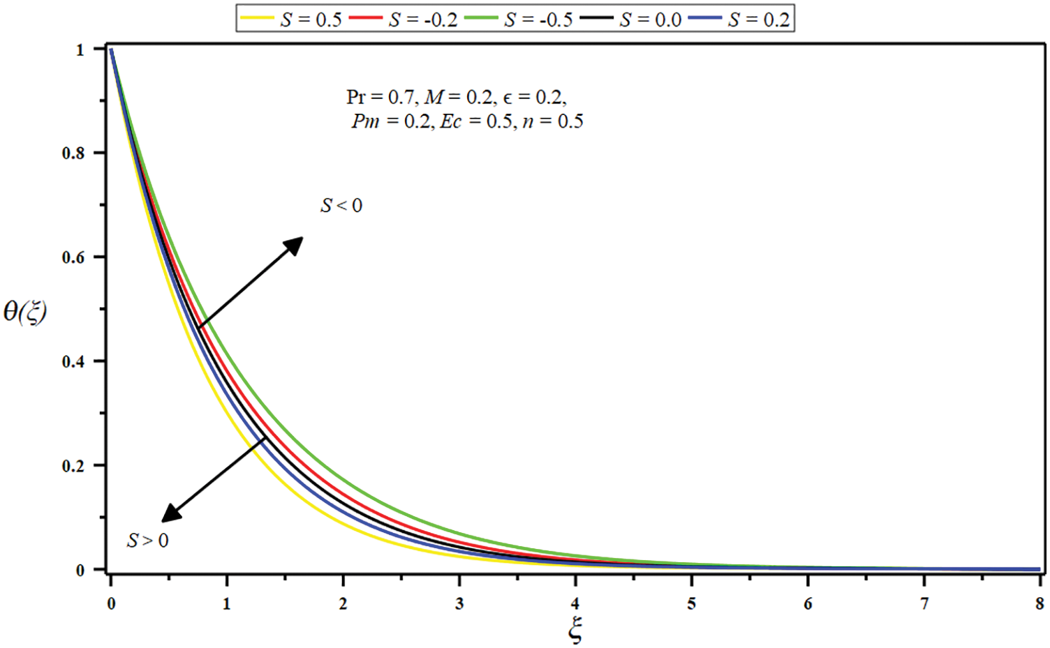
Figure 16: Impact of suction/injection parameter
Force convection in micropolar and stagnation point flow with thermal radiation and viscous dissipation adjacent to a permeable stretching sheet in porous dissipation is delivered numerically and examined. The core findings are outlined as follows:
• The flow is intensified, and momentum slop diminishes with mounting values of constant ration parameter (less than unity), boundary parameter, porosity parameter, and suction parameter.
• The flow is slackened, and momentum slop amplified with growing values of constant ration parameter (more significant than unity), micropolar parameter, and injection parameter.
• The micro-rotation velocity (angular velocity) is stifled. The boundary slop is amplified with escalating boundary parameter, porosity parameter, suction parameter, and a small interval of the micropolar parameter. Contrariwise, the micro-rotation velocity is minor with intensifying values of the constant ratio parameter, a huge micropolar parameter, injection parameter, and a small interval of porosity parameter.
• The growing amount of the Eckert number, micropolar parameter, porosity parameter, and injection parameter raises the temperature and improves thermal boundary depth. Conversely, the temperature and boundary layer decline by growing the Prandtl number and suction parameter values.
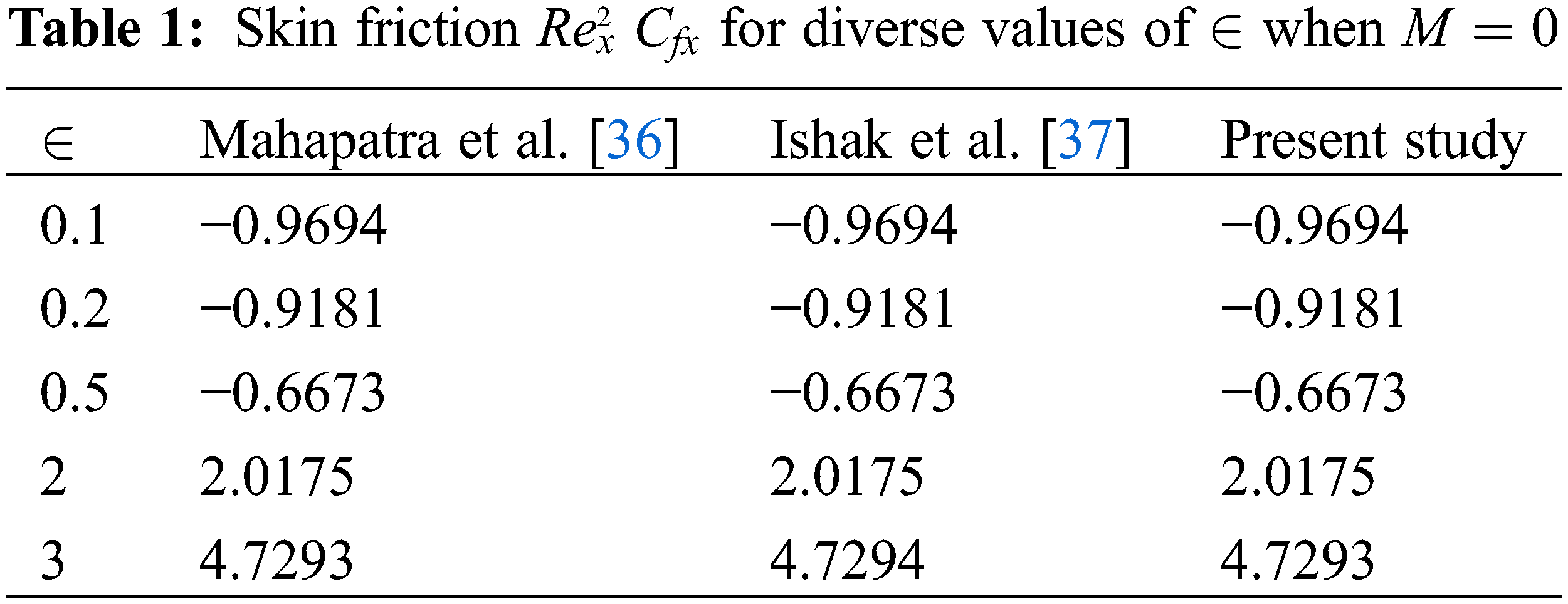
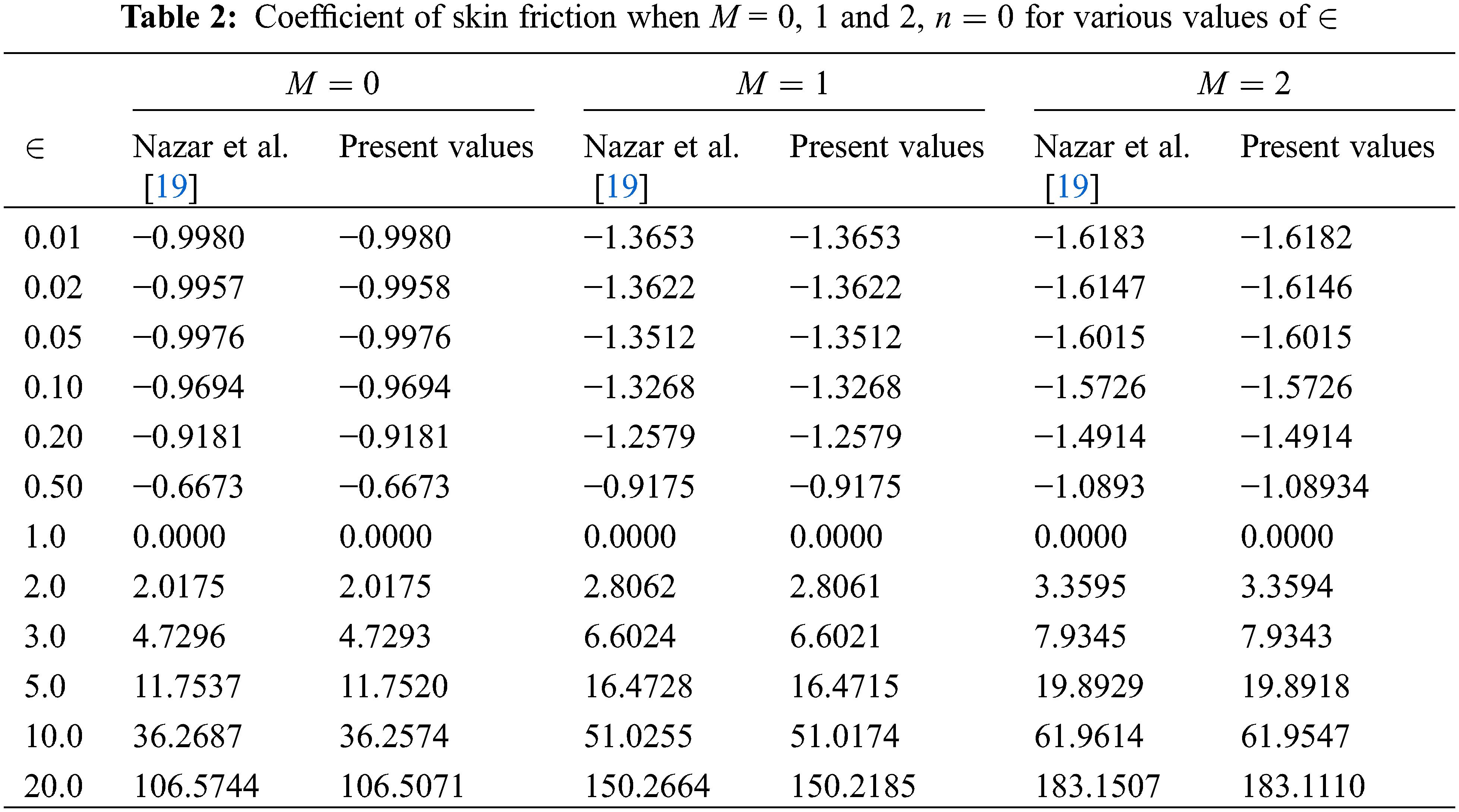
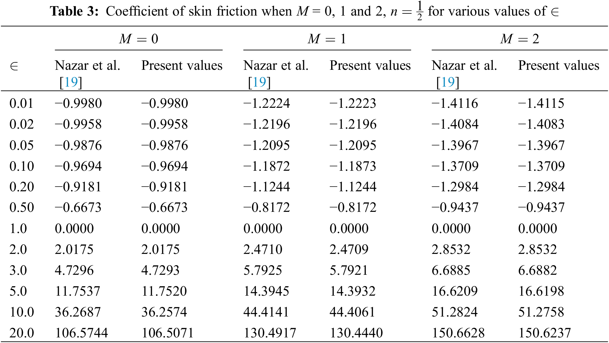
• It is significant to notice that the skin friction coefficient rises as the constant ratio parameter is amplified.
Acknowledgement: The third author would like to thank University of Education, Lahore, Pakistan for the financial support.
Funding Statement: The authors received no specific funding for this study.
Conflicts of Interest: The authors declare that they have no conflicts of interest to report regarding the present study.
References
1. Eringen, A. C. (1966). Theory of micropolar fluids. Journal of Mathematics and Mechanics, 16(1), 1–18. DOI 10.1512/iumj.1967.16.16001. [Google Scholar] [CrossRef]
2. Eringen, A. C. (1972). Theory of thermo-microfluids. Journal of Mathematical Analysis and Applications, 38(2), 480–496. DOI 10.1016/0022-247X(72)90106-0. [Google Scholar] [CrossRef]
3. Hussanan, A., Salleh, M. Z., Khan, I. (2018). Microstructure and inertial characteristics of a magnetite ferrofluid over a stretching/shrinking sheet using effective thermal conductivity model. Journal of Molecular Liquids, 255(1), 64–75. DOI 10.1016/j.molliq.2018.01.138. [Google Scholar] [CrossRef]
4. Mishra, S. R., Khan, I., Al-Mdallal, Q. M., Asifa, T. (2018). Free convective micropolar fluid flow and heat transfer over a shrinking sheet with heat source. Case Studies in Thermal Engineering, 11(3), 113–119. DOI 10.1016/j.csite.2018.01.005. [Google Scholar] [CrossRef]
5. Bhat, A., Katagi, N. N. (2020). Micropolar fluid flow between a non-porous disk and a porous disk with slip: Keller-box solution. Ain Shams Engineering Journal, 11(1), 149–159. DOI 10.1016/j.asej.2019.07.006. [Google Scholar] [CrossRef]
6. Shehzad, S. A., Reddy, M. G., VIjayakumari, P., Tlili, I. (2020). Behavior of ferromagnetic Fe2SO4 and titanium alloy Ti6Al4v nanoparticles in micropolar fluid flow. International Communications in Heat and Mass Transfer, 117, 104769. DOI 10.1016/j.icheatmasstransfer.2020.104769. [Google Scholar] [CrossRef]
7. Ali, B., Shafiq, A., Siddique, I., Al-Mdallal, Q., Jarad, F. (2021). Significance of suction/injection, gravity modulation, thermal radiation, and magnetohydrodynamic on dynamics of micropolar fluid subject to an inclined sheet via finite element approach. Case Studies in Thermal Engineering, 28(1856), 101537. DOI 10.1016/j.csite.2021.101537. [Google Scholar] [CrossRef]
8. Siddiqa, S., Begum, N., Hossain, M. A., Abrar, M. N., Gorla, R. S. R. et al. (2021). Effect of thermal radiation on conjugate natural convection flow of a micropolar fluid along a vertical surface. Computers & Mathematics with Applications, 83, 74–83. DOI 10.1016/j.camwa.2020.01.011. [Google Scholar] [CrossRef]
9. Slayi, S., Arwadi, T. E. A., Dib, S. (2021). Stabilized Gauge Uzawa scheme for an incompressible micropolar fluid flow. Applied Numerical Mathematics, 167(1), 45–72. DOI 10.1016/j.apnum.2021.04.003. [Google Scholar] [CrossRef]
10. Siddiqui, A. A., Turkyilmazoglu, M. (2022). Slit flow and thermal analysis of micropolar fluids in a symmetric channel with dynamic and permeable. International Communications in Heat and Mass Transfer, 132(6), 105844. DOI 10.1016/j.icheatmasstransfer.2021.105844. [Google Scholar] [CrossRef]
11. Shamshuddin, M., Krishna, C. B. (2019). Heat absorption and joule heating effects on transient free convective reactive micropolar fluid flow past a vertical porous plate. Fluid Dynamics & Materials Processing, 15(3), 207–231. DOI 10.32604/fdmp.2019.00449. [Google Scholar] [CrossRef]
12. Abo-Dahab, S. M., Hatem, A. (2020). Solution of a free convection effect on oscillatory flow of an electrically conducting micropolar concentration fluid with thermal relaxation within porous medium. Alexandria Engineering Journal, 59(3), 1243–1257. DOI 10.1016/j.aej.2020.02.011. [Google Scholar] [CrossRef]
13. Turkyilmazoglu, M. (2016). Flow of a micropolar fluid due to a porous stretching sheet and heat transfer. International Journal of Nonlinear Mechanics, 83, 59–64. DOI 10.1016/j.ijnonlinmec.2016.04.004. [Google Scholar] [CrossRef]
14. Hussanan, A., Khan, I., Khan, W. A., Chen, Z. (2020). Micropolar mixed convective flow with Cattaneo-Christov heat flux: Non-Fourier heat conduction analysis. Thermal Science, 24(2B), 1345–1356. [Google Scholar]
15. Zadeh, S. M. H., Mehryan, S. A. M., Sheremet, M. A., Izadi, M., Ghodrat, M. (2020). Numerical study of mixed bio-convection associated with a micropolar fluid. Thermal Science and Engineering Progress, 18, 100539. DOI 10.1016/j.tsep.2020.100539. [Google Scholar] [CrossRef]
16. Singh, K., Pandey, A. K., Kumar, M. (2020). Slip flow of micropolar fluid through a permeable wedge due to the effects of chemical reaction and heat source/sink with hall and ion-slip currents: An analytic approach. Propulsion and Power Research, 9(3), 289–303. DOI 10.1016/j.jppr.2020.04.006. [Google Scholar] [CrossRef]
17. Saad, E. I., Faltas, M. S. (2020). Thermophoresis of a spherical particle straddling the interface of a semi-infinite micropolar fluid. Journal of Molecular Liquids, 312, 113289. DOI 10.1016/j.molliq.2020.113289. [Google Scholar] [CrossRef]
18. Fatunmbi, E. O., Ogunseye, H. A., Sibanda, P. (2020). Magnetohydrodynamic micropolar fluid flow in a porous medium with multiple slip conditions. International Communications in Heat and Mass Transfer, 115, 104577. DOI 10.1016/j.icheatmasstransfer.2020.104577. [Google Scholar] [CrossRef]
19. Nazar, R., Amin, N., Filip, D., Pop, I. (2004). Stagnation point flow of a micropolar fluid towards a stretching sheet. International Journal of Nonlinear Mechanics, 39(7), 1227–1235. DOI 10.1016/j.ijnonlinmec.2003.08.007. [Google Scholar] [CrossRef]
20. Abbas, N., Saleem, S., Nadeem, S., Alderremy, A. A., Khan, A. U. (2018). On stagnation point flow of a micro polar nanofluid past a circular cylinder with velocity and thermal slip. Results in Physics, 9(2), 1224–1232. DOI 10.1016/j.rinp.2018.04.017. [Google Scholar] [CrossRef]
21. Soomro, F. A., Haq, R. U., Al-Mdallal, Q. M., Zhang, Q. (2018). Heat generation/absorption and nonlinear radiation effects on stagnation point flow of nanofluid along a moving surface. Results in Physics, 8(1), 404–414. DOI 10.1016/j.rinp.2017.12.037. [Google Scholar] [CrossRef]
22. Besthapu, P., Haq, R. U., Bandari, S., Al-Mdallal, Q. M. (2019). Thermal radiation and slip effects on MHD stagnation point flow of non-Newtonian nanofluid over a convective stretching surface. Neural Computing and Applications, 31(1), 207–217. DOI 10.1007/s00521-017-2992-x. [Google Scholar] [CrossRef]
23. Khan, M. I., Nigar, M., Hayat, T., Alsaedi, A. (2020). On the numerical simulation of stagnation point flow of non-Newtonian fluid (Carreau fluid) with Cattaneo-Christov heat flux. Computer Methods and Programs in Biomedicine, 187, 105247. DOI 10.1016/j.cmpb.2019.105247. [Google Scholar] [CrossRef]
24. Abbas, N., Malik, M. Y., Alqarni, M. S., Nadeem, S. (2020). Study of three dimensional stagnation point flow of hybrid nanofluid over an isotropic slip surface. Physica A: Statistical Mechanics and its Applications, 554(14), 124020. DOI 10.1016/j.physa.2019.124020. [Google Scholar] [CrossRef]
25. Abbasi, A., Mabood, F., Farooq, W., Hussain, Z. (2020). Non-orthogonal stagnation point flow of Maxwell nano-material over a stretching cylinder. International Communications in Heat and Mass Transfer, 120, 105043. DOI 10.1016/j.icheatmasstransfer.2020.105043. [Google Scholar] [CrossRef]
26. Arani, A. A. A., Aberoumand, H. (2021). Stagnation-point flow of Ag-CuO/water hybrid nanofluids over a permeable stretching/shrinking sheet with temporal stability analysis. Powder Technology, 380(17), 152–163. DOI 10.1016/j.powtec.2020.11.043. [Google Scholar] [CrossRef]
27. Muthtamilselvan, M., Suganya, S., Al-Mdallal, Q. M. (2021). Stagnation-point flow of the williamson nanofluid containing gyrotactic micro-organisms. Proceedings of the National Academy of Sciences, India Section A: Physical Sciences, 91(4), 633–648. DOI 10.1007/s40010-021-00764-7. [Google Scholar] [CrossRef]
28. Renuka, A., Muthtamilselvan, M., Al-Mdallal, Q. M., Doh, D. H., Abdalla, B. (2021). Unsteady separated stagnation point flow of nanofluid past a moving flat surface in the presence of buongiorno’s model. Journal of Applied and Computational Mechanics, 7(3), 1283–1290. [Google Scholar]
29. Turkyilmazoglu, M. (2021). Stagnation-point flow and heat transfer over stretchable plates and cylinders with an oncoming flow: Exact solutions. Chemical Engineering Science, 238(2), 116596. DOI 10.1016/j.ces.2021.116596. [Google Scholar] [CrossRef]
30. Alhamaly, A. S., Khan, M., Shuja, S. Z., Yilbas, B. S., Al-Qahtani, H. (2021). Axisymmetric stagnation point flow on linearly stretching surfaces and heat transfer: Nanofluid with variable physical properties. Case Studies in Thermal Engineering, 24, 100839. DOI 10.1016/j.csite.2021.100839. [Google Scholar] [CrossRef]
31. Zainal, N. A., Nazar, R., Naganthran, K., Pop, I. (2020). MHD mixed convection stagnation point flow of a hybrid nanofluid past a vertical flat plate with convective boundary condition. Chinese Journal of Physics, 66, 630–644. DOI 10.1016/j.cjph.2020.03.022. [Google Scholar] [CrossRef]
32. Vijaya, N., Venkata, G., Krishna, Y. H. (2019). Non-aligned stagnation point flow of a casson fluid past a stretching sheet in a doubly stratified medium. Fluid Dynamics & Materials Processing, 15(3), 233–251. DOI 10.32604/fdmp.2019.03727. [Google Scholar] [CrossRef]
33. Sarkar, S., Sahoo, B. (2020). Analysis of oblique stagnation point flow over a rough surface. Journal of Mathematical Analysis and Applications, 490(1), 124208. DOI 10.1016/j.jmaa.2020.124208. [Google Scholar] [CrossRef]
34. Rizwan, R., Nadeem, S. (2020). Series solution of unsteady MHD oblique stagnation point flow of copper-water nanofluid flow towards Riga plate. Heliyon, 6(10), e04689. DOI 10.1016/j.heliyon.2020.e04689. [Google Scholar] [CrossRef]
35. Shafiq, A., Mebarek-Oudina, F., Sindhu, T. N., Abidi, A. (2021). A study of dual stratification on stagnation point Walters’ B nanofluid flow via radiative Riga plate: A statistical approach. The European Physical Journal Plus, 136(4), 1–24. DOI 10.1140/epjp/s13360-021-01394-z. [Google Scholar] [CrossRef]
36. Mahapatra, T. R., Gupta, A. S. (2002). Heat transfer in stagnation-point flow towards a stretching sheet. Heat and Mass Transfer, 38(6), 517–521. DOI 10.1007/s002310100215. [Google Scholar] [CrossRef]
37. Ishak, A., Nazar, R., Pop, I. (2006). Mixed convection boundary layers in the stagnation-point flow toward a stretching vertical sheet. Meccanica, 41(5), 509–518. DOI 10.1007/s11012-006-0009-4. [Google Scholar] [CrossRef]
38. Chu, Y. M., Rehman, M. I. U., Khan, M. I., Nadeem, S., Kadry, S. et al. (2020). Transportation of heat and mass transport in hydromagnetic stagnation point flow of Carreau nanomaterial: Dual simulations through Runge-Kutta Fehlberg technique. International Communications in Heat and Mass Transfer, 118, 104858. DOI 10.1016/j.icheatmasstransfer.2020.104858. [Google Scholar] [CrossRef]
39. Abd El-Aziz, M. (2009). Viscous dissipation effect on mixed convection flow of a micropolar fluid over an exponentially stretching sheet. Canadian Journal of Physics, 87(4), 359–368. DOI 10.1139/P09-047. [Google Scholar] [CrossRef]
40. Pal, D., Mandal, G. (2015). Mixed convection-radiation on stagnation-point flow of nanofluids over a stretching/shrinking sheet in a porous medium with heat generation and viscous dissipation. Journal of Petroleum Science and Engineering, 126(11), 16–25. DOI 10.1016/j.petrol.2014.12.006. [Google Scholar] [CrossRef]
41. Fatunmbi, E. O., Adeniyan, A. (2018). MHD stagnation point-flow of micropolar fluids past a permeable stretching plate in porous media with thermal radiation, chemical reaction and viscous dissipation. Journal of Advances in Mathematics and Computer Science, 26(1), 1–19. DOI 10.9734/JAMCS/2018/38595. [Google Scholar] [CrossRef]
42. Afridi, M. I., Qasim, M. (2019). Second law analysis of Blasius flow with nonlinear Rosseland thermal radiation in the presence of viscous dissipation. Propulsion and Power Research, 8(3), 234–242. DOI 10.1016/j.jppr.2018.06.001. [Google Scholar] [CrossRef]
43. Rasool, G., Shafiq, A., Chu, Y. M., Bhutta, M. S., Ali, A. (2021). Optimal homotopic exploration of features of cattaneo-christov model in second grade nanofluid flow via darcy-forchheimer medium subject to viscous dissipation and thermal radiation. Combinatorial Chemistry & High Throughput Screening. DOI 10.2174/1386207324666210903144447. [Google Scholar] [CrossRef]
44. Haq, R. U., Sajjad, T., Ullah, M. Z., Alshomrani, A. S., Tlili, I. (2020). Dual nature solutions of water-based carbon nanotubes along a shrinking surface in the presence of thermal radiation and viscous dissipation. International Communications in Heat and Mass Transfer, 119(6), 104938. DOI 10.1016/j.icheatmasstransfer.2020.104938. [Google Scholar] [CrossRef]
45. Shamshuddin, M., Mishra, S. R., Bég, O. A., Kadir, A. (2019). Viscous dissipation and joule heating effects in non-Fourier MHD squeezing flow, heat and mass transfer between Riga plates with thermal radiation: Variational parameter method solutions. Arabian Journal for Science and Engineering, 44(9), 8053–8066. DOI 10.1007/s13369-019-04019-x. [Google Scholar] [CrossRef]
46. Patel, H. R., Singh, R. (2019). Thermophoresis, Brownian motion and nonlinear thermal radiation effects on mixed convection MHD micropolar fluid flow due to nonlinear stretched sheet in porous medium with viscous dissipation, joule heating and convective boundary condition. International Communications in Heat and Mass Transfer, 107(1), 68–92. DOI 10.1016/j.icheatmasstransfer.2019.05.007. [Google Scholar] [CrossRef]
47. Megahed, A. M. (2019). Williamson fluid flow due to a nonlinearly stretching sheet with viscous dissipation and thermal radiation. Journal of the Egyptian Mathematical Society, 27(1), 1–10. DOI 10.1186/s42787-019-0016-y. [Google Scholar] [CrossRef]
48. Gireesha, B. J., Archana, M., Kumar, P. S., Gorla, R. S. R. (2019). Significance of temperature dependent viscosity, nonlinear thermal radiation and viscous dissipation on the dynamics of water conveying cylindrical and brick shaped molybdenum disulphide nanoparticles. International Journal of Applied and Computational Mathematics, 5(3), 1–15. DOI 10.1007/s40819-019-0649-4. [Google Scholar] [CrossRef]
49. Hussanan, A., Salleh, M. Z., Khan, I., Shafie, S. (2018). Analytical solution for suction and injection flow of a viscoplastic Casson fluid past a stretching surface in the presence of viscous dissipation. Neural Computing and Applications, 29(12), 1507–1515. DOI 10.1007/s00521-016-2674-0. [Google Scholar] [CrossRef]
50. Mahanthesh, B., Gireesha, B. J. (2018). Scrutinization of thermal radiation, viscous dissipation and Joule heating effects on Marangoni convective two-phase flow of Casson fluid with fluid-particle suspension. Results in Physics, 8(6), 869–878. DOI 10.1016/j.rinp.2018.01.023. [Google Scholar] [CrossRef]
51. Ahmadpour, A., Nasiri, M., Khazayinejad, M., Asgharian, N. (2018). Flow and convective heat transfer of Casson fluid between squeezing porous disks in the presence of thermal radiation, viscous dissipation, and variable heat source/sink. Journal of the Brazilian Society of Mechanical Sciences and Engineering, 40(3), 1–13. DOI 10.1007/s40430-018-1058-z. [Google Scholar] [CrossRef]
52. Ghoneim, N. I., Megahed, A. M. (2022). Hydromagnetic nanofluid film flow over a stretching sheet with prescribed heat flux and viscous dissipation. Fluid Dynamics & Materials Processing, 18(5), 1373–1388. DOI 10.32604/fdmp.2022.020509. [Google Scholar] [CrossRef]
53. Mishra, A., Kumar, M. (2020). Thermal performance of mhd nanofluid flow over a stretching sheet due to viscous dissipation, joule heating and thermal radiation. International Journal of Applied and Computational Mathematics, 6(4), 1–17. DOI 10.1007/s40819-020-00869-4. [Google Scholar] [CrossRef]
54. Aziz, A., Jamshed, W., Aziz, T., Bahaidarah, H. M., Rehman, K. U. (2021). Entropy analysis of Powell-Eyring hybrid nanofluid including effect of linear thermal radiation and viscous dissipation. Journal of Thermal Analysis and Calorimetry, 143(2), 1331–1343. DOI 10.1007/s10973-020-10210-2. [Google Scholar] [CrossRef]
55. Yusuf, T. A., Mabood, F., Khan, W. A., Gbadeyan, J. A. (2020). Irreversibility analysis of Cu-TiO2-H2O hybrid-nanofluid impinging on a 3-D stretching sheet in a porous medium with nonlinear radiation: Darcy-Forchhiemer’s model. Alexandria Engineering Journal, 59(6), 5247–5261. DOI 10.1016/j.aej.2020.09.053. [Google Scholar] [CrossRef]
56. Sharanappa, D. S., Tawade, J. V., Veena, M. B., Pallavi, S. P. (2020). MHD boundary layer flow of a Casson nano liquid over a penetrable linearly stretching sheet with frictional heating effects in Brinkmann-Forcheiemerr porous medium. https://doi.org/10.1016/j.matpr.2020.10.125. [Google Scholar]
57. Kausar, M. S., Hussanan, A., Mamat, M., Ahmad, B. (2019). Boundary layer flow through Darcy-Brinkman porous medium in the presence of slip effects and porous dissipation. Symmetry, 11(5), 659. DOI 10.3390/sym11050659. [Google Scholar] [CrossRef]
58. Irfan, M., Farooq, M. A. (2020). Thermophoretic MHD free stream flow with variable internal heat generation/absorption and variable liquid characteristics in a permeable medium over a radiative exponentially stretching sheet. Journal of Materials Research and Technology, 9(3), 4855–4866. DOI 10.1016/j.jmrt.2020.03.005. [Google Scholar] [CrossRef]
59. Goud, B. S. (2020). Heat generation/absorption influence on steady stretched permeable surface on MHD flow of a micropolar fluid through a porous medium in the presence of variable suction/injection. International Journal of Thermofluids, 7, 100044. DOI 10.1016/j.ijft.2020.100044. [Google Scholar] [CrossRef]
60. Turkyilmazoglu, M. (2015). An analytical treatment for the exact solutions of MHD flow and heat over two-three dimensional deforming bodies. International Journal of Heat and Mass Transfer, 90, 781–789. DOI 10.1016/j.ijheatmasstransfer.2015.07.025. [Google Scholar] [CrossRef]
61. Hussanan, A., Salleh, M. Z., Khan, I., Tahar, R. M. (2018). Heat and mass transfer in a micropolar fluid with Newtonian heating: An exact analysis. Neural Computing and Applications, 29(6), 59–67. DOI 10.1007/s00521-016-2516-0. [Google Scholar] [CrossRef]
62. Turkyilmazoglu, M. (2016). Flow of a micropolar fluid due to a porous stretching sheet and heat transfer. International Journal of Non-Linear Mechanics, 83, 59–64. DOI 10.1016/j.ijnonlinmec.2016.04.004. [Google Scholar] [CrossRef]
 | This work is licensed under a Creative Commons Attribution 4.0 International License, which permits unrestricted use, distribution, and reproduction in any medium, provided the original work is properly cited. |