| Fluid Dynamics & Materials Processing |
DOI: 10.32604/fdmp.2022.019922
ARTICLE
Application of Vortex Generators to Remove Heat Trapped in Closed Channels
1School of Accounting, Jiujiang University, Jiujiang, 332000, China
2General Directorate of Education in Al-Muthanna Governorate, Ministry of Education, Samawah, 66001, Iraq
3Department of Mechanical Engineering, Faculty of Science and Technology, Universitas Muhammadiyah Kalimantan Timur, Samarinda, 75124, Indonesia
4College of Petroleum Engineering, Al-Ayen University, Thi-Qar, 64001, Iraq
5National Research Tomsk Polytechnic University, Tomsk, 634050, Russia
6Kazan Federal University, Kazan, 420008, Russian
7Nosov Magnitogorsk State Technical University, Magnitogorsk, 455000, Russia
8Department of Dentistry, Kut University College, Kut, Wasit, 52001, Iraq
9College of Technical Engineering, The Islamic University, Najaf, 7003, Iraq
10Department of Pharmacy, OsolAldeen University College, Baghdad, 993P+PWX, Iraq
11Faculty of Biology and Ecology, Yanka Kupala State University of Grodno, Grodno, 230023, Belarus
12College of Technical Engineering, The Islamic University, Najaf, 7003, Iraq
*Corresponding Author: Alim Al Ayub Ahmed. Email: alnassar.wala.ismael@gmail.com
Received: 24 October 2021; Accepted: 14 March 2022
Abstract: The utilization of vortex generators to increase heat transfer from cylinders installed inside a duct is investigated. In particular, a channel containing eight cylinders with volumetric heat sources is considered for different values of the Reynolds number. The effective possibility to use vortex generators with different sizes to increase heat transfer and, consequently, reduce the surface temperature of the cylinders is examined. Also, the amount of pressure drop inside the channel due to the presence of vortex generators is considered and compared with the cases without vortex generators. The results show that although the addition of generators increases the pressure drop, it strongly contributes to increase the heat transfer coefficient inside the duct (up to 80–90%).
Keywords: Vortex generators; heat trapped; temperature of hot surfaces; heat transfer
In today’s world, one of the essential human concerns is reducing energy consumption and consequently reducing fossil fuels consumption. On the one hand, the limited energy resources and, on the other hand, air pollution due to the excessive use of fossil fuels have led researchers to study and introduce various methods to reduce energy consumption. One of the most important ways to reduce energy consumption is to use techniques to increase heat transfer [1–4]. Humans have long considered methods of increasing heat transfer, but in recent years its importance has increased and researchers have conducted many types of research to introduce various methods of increasing heat transfer [5–9]. Zhou et al. used ultrasound to increase the heat transferred inside the mini-channel [5]. They detected and investigated the mechanism of using this method using high-speed cameras and stated that the maximum increase in heat transfer was 53.9%. Wu et al. studied the effects of increasing heat transfer using a single fin inside phase-change materials (PCMs) [6]. After examining the effect of different locations for fan placement, they finally introduced the best locations with the greatest impact on increasing heat transfer for different lengths of fins. Using a new kind of twined coil, Dang et al. examined the rate of increase in heat transfer through a circular tube [7]. They introduced the main mechanism for increasing heat transfer, the twined coil insert, and stated that the Reynolds 1000 had a maximum efficiency of 2.16 times at a given mass flow rate. Nourdanesh et al. [8] used the electric field to create a secondary fluid flow inside the channel and investigated the effects of the electric field on increasing heat transfer in different fluid flows. They stated that by using an electric field and creating bubbles in the fluid, they are able to increase the heat transfer at different fluid flows into the channel. Wang et al. investigated heat transfer within a microchannel using symmetric and parallel wavy microchannels over a wide range of Reynolds numbers [9]. They stated that Modified parallel configurations generally had a better effect on increasing heat transfer, and Modified symmetric configurations had better effects locally.
One of the most important applications is to increase heat transfer in cooling systems. Cooling is one of the most important parts of design in various industries, which in the absence of temperature management in the operation of temperature systems can lead to early depreciation and failure of these systems or cause irreparable disasters. Numerous articles on cooling systems of applications in various industries have been presented by researchers [10–14]. These industries include aerospace, petrochemical, automotive, electronics, food and medicine industries, etc. Li et al. [10] examined the performance of the system based on the performance of the heat exchanger. They argued that heat exchanger optimization could bring many benefits at the expense of low costs. The study also found that they could save as much as 13.3 percent in energy consumption. Xin and colleagues improved heat transfer to reduce the cold temperature and dead volume of the Stirling engine [11]. They stated that the use of heat pipes with heat dissipation capability and relatively low pressure drop would have tremendous potential in the Stirling engine. Xie et al. [12] used the rib-bed plate structure to reduce the overheating of the stagnant engine body and improve its performance. Their results show that the cooling structure presented with rib-bed plate in the inner wall improves the cooling performance. Nourdanesh et al. [13] experimentally used the effects of an electric field on a dielectric fluid to cool a flowing liquid inside an open channel. They applied the cooling rate of the fluid in different fluid thicknesses for different applied voltages and while announcing the significant effect of the electric field on increasing the cooling rate of the fluid, they introduced the thickness of 6 mm fluid inside the channel as the optimal thickness for their system performance. Izadi et al. [14] cooled the CPU using a nanofluid under the influence of a magnetic field. They stated that the use of a stronger magnetic field is useful for increasing heat transfer with highly porous metal foam.
Numerous methods have been introduced by researchers to increase the heat transfer and cooling of temperature systems. In general, methods of increasing heat transfer can be divided into two categories: passive and active. In the passive method, no external forces are used to transfer heat, and therefore no energy is spent on cooling the system, but in the active method, external forces are used to increase heat transfer. Although the amount of heat transferred is generally higher in active methods than in passive methods, but in active methods we have to spend external energy to increase the amount of heat transferred. Therefore, one of the important advantages of using passive methods is that there is no need to consume additional energy to increase heat transfer. For example, Zharfa et al. [15] have evaluated the performance of helical coils as a method of increasing passive heat transfer. Their findings show that, for spiral and straight pipes, entropy production increases with increasing pipe diameter, mass velocity, vapor quality and wall heat flux, and decreasing saturation temperature. Matteo Fasano and colleagues also studied the increase in passive heat transfer using a 3D printed Pitot tube-based heat sink [16]. Their initial tests show that the proposed heatsink can increase heat transfer by up to 98% compared to conventional sinks. As an active method in [17], Roozitalab investigated the effect of flow vortices as an active method on increasing heat transfer. Their research results show that compared to fixed vortex generating technologies, vibrating spherical cylinders can effectively improve heat transfer performance and lead to less pressure drop. Nourdanesh et al. [18] used volumetric electric force on the fluid as an active method to increase heat transfer and by changing the direction of fluid flow and creating vortices on the hot plates of the solar collector to increase heat transfer from the irradiated plates to Fluidized and thus increased the efficiency of plate solar collectors. Wayne et al. [19] investigated the increase in heat transfer displacement in a heat sink using integrated and cross-propellers. Their results showed that heat transfer in integrated fans is a function of system performance and has a weak dependence on fan geometry.
Various techniques can be introduced as a passive method to increase heat transfer. These include changes in the roughness of the pages [20], changes in geometry [21], the use of generator vortex [22,23] and vertex generators [24,25] are protruding protrusions in the system that cause heat transfer in the trapped system by changing the direction of the fluid and creating secondary currents, thus increasing the heat transfer and preventing the local temperature from rising. Qu et al. [22] increased the heat and mass transfer in a microchannel through the oscillations of a flexible generator vortex. The results of their research showed that the Darcy coefficient of friction decreases by 42.33% and the coefficient of thermal performance increases by 42%. Using vortex generators with different angles, Jeong et al. [26] numerically investigated the increase in heat transfer in a channel. Their results showed that the dimpled channel with Vertex Generator shows better thermal performance than the general dimpled channel.
In the present study, Vertex Generator has been used to increase the cooling of the cylinders installed inside the closed channel. Although many researches have been done by researchers in order to increase the heat transfer by Vertex Generator, but the design of Vertex Generator has been done in this research for cooling cylinders with arrangement in which heat is generated in volume in previous researches. Therefore, in this study, to increase the heat transfer and cooling of the cylinders, different vortex generators have been added to the system and its effects have been compared with the case where no generator vortex has been used in the system.
Fig. 1 shows a top view of the schematic of the problem and the arrangement of the cylinders inside the channel. As shown in the figure, eight cylinders are placed vertically inside the channel with a length of 500 mm and a height of 200 mm. Cylinders with a radius of 15 mm have a volumetric heat source of 10–7 W/m3. The inlet fluid enters the channel from the left at different speeds at a temperature of 20°C and leaves the channel from the right after passing through the channel and cooling the cylinders. Inside the channel, vortex generators have been used to increase the rate of heat transfer and cooling of most cylinders, and the effects of using vortex generators in the absence of vortex generators have been compared and investigated.
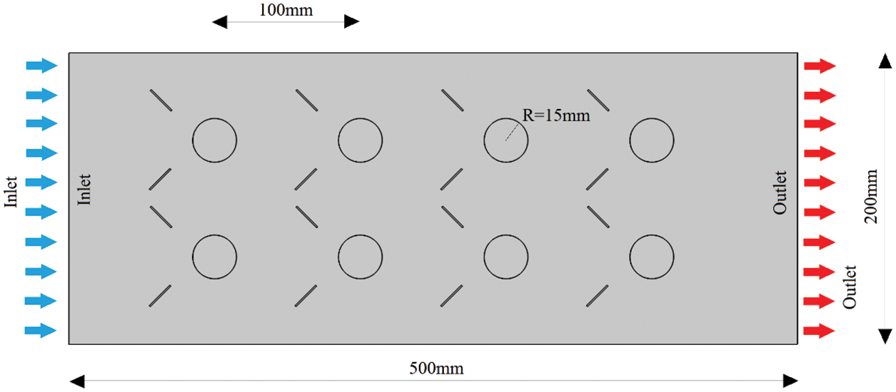
Figure 1: Design and geometry of the problem under study
Forced entry of fluid into the channel at different speeds and Reynolds and passing it around the cylinders causes the cylinder to cool. Due to the fact that the operating fluid is in the water channel and considering the low Reynolds numbers for the inlet fluid in the channel, Navier–Stokes relations for the fluid flow are considered as incompressible fluid with viscous dynamicsand a steady state condition. PISO procedure for pressure-velocity calculation in the Navier-Stokes equations has been adapted to this steady-state problem [27,28]. Hence the Navier–Stokes relations used in this case are as follows:
where ρ is the density of the fluid, t is the time, u is the velocity of the fluid, p is the pressure, and μ is the viscosity of the fluid inside the channel. For incompressible fluid, we will have the continuity equation as follows:
To calculate the Reynolds number at the channel input, we have the following relation:
where V is the average velocity of the fluid at the channel inlet and Dh is the hydraulic diameter of the channel inlet, which is obtained from the following equation:
where a and b are the length and width of the channel. To obtain the temperature distribution inside the channel as well as the amount of heat transferred from the cylinders to the fluid, we will have the following energy relationship:
In this regard, Cp is the specific heat capacity of the fluid at constant pressure, T is the fluid temperature, k is the coefficient of thermal conductivity which takes different values according to whether it is evaluated in the fluid or inside the (solid) cylinders, and qs is the amount of heat produced per unit volume inside the cylinders. qs takes a non-zero value only inside the cylinders, and it is set to zero otherwise.
The following equation is used to compare the vortex performance of generators to calculate the heat transfer coefficient of displacement within the channel.
Q is the total heat transferred from the cylinders, h is the average heat transfer coefficient of the fluid movement inside the channel and ∆T is the temperature difference between the inlet fluid Tin and the average temperature on the surface of the cylinders Ts, which is obtained from the following equation:
To better compare the rate of increase in heat transfer due to the use of vortex generators, the Nusselt dimensionless number is used, which is obtained from the following equation:
To solve the fluid flow relations, the boundary conditions determined in this case are as follows: the left side of the velocity inlet channel and the right side of the velocity outlet channel, and the upper walls and cylinder surfaces are considered to be wall-to-wall with the principle of non-slip. To solve the energy equations, the input of the left channel below is considered as a constant temperature at 20°C and the output of the right is as an outlet. The upper and lower walls of the duct are designated as heat insulators and the cylinders are designated as heat sources per unit volume. Thermal conduction was considered for solid phases and thermal convection was considered for the fluid phase.
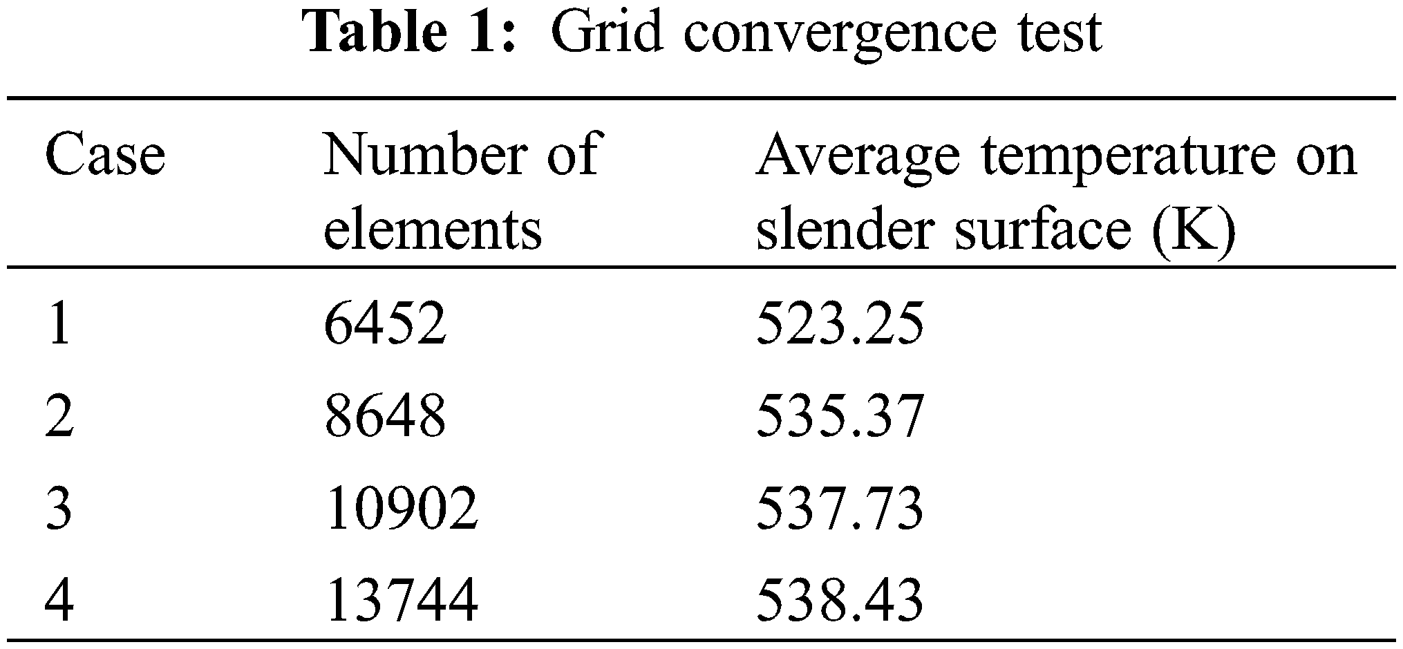
To solve this problem, COMSOL Multiphysics commercial software has been used, which is based on the Finite-element method. A non-uniform free-triangular grid was used to network the problem geometry and to solve the problem independently of the network effects; different elements were performed and compared with the average temperature on the cylinders in a state that is shown in Table 1. According to the results shown in the table, it is clear that in elements greater than 10902, the average temperature change of the cylinder surface is very small, so this networking has been used to solve all problem modes.
In this section, the simulation and discussion of the results by creating the vortex of generators on the fluid motion path and by changing the fluid motion path and directing it on cylindrical cylinders was presented. It was used to enhance the heat transfer of the cylinders to the fluid flow to reduce the average surface temperature of the closed channels, which are in good agreement with the results of reference [4]. Also, the behavior of thermal and fluid boundary layers on solid surfaces can be considered for the validity of this study. Fig. 2 shows the temperature and velocity distribution of the fluid inside the duct while no generator vortex is used (Case 1) and the only cooling factor of the cylinders is the passage of fluid around them at the applied velocity. As can be seen from the figure, due to the arrangement of the cylinders in two rows in a row, the front cylinders on one side reduce the speed of the fluid passing around the rear cylinders and on the other hand the heat transferred from the front cylinders to the fluid which causes The heating of the fluid has again passed the same heated fluid through the rear cylinders and significantly reduces the heat transfer in the rear cylinders. The whole system of average temperature of the cylinder surface also increases.

Figure 2: Distribution of temperature and fluid velocity inside the channel without the presence of vortex generators
In Fig. 3, unlike the previous case, generators are added on both sides of each Vertex cylinder (Case 2). As can be seen from the figure, the placement of the generators’ vertex in the direction of the main motion of the fluid causes the fluid to change direction from the empty parts without the cylinder to around and on the cylinders. This phenomenon, in addition to increasing the velocity of the fluid on the cylinders, which in the previous case was reduced due to the effect of the front cylinders, also leads to a cooler fluid around the cylinders and thus the hot fluid trapped between the cylinders to empty areas without cylinders. Which leads to cooler. Therefore, this action increases the heat transfer from the cylinders to the fluid and reduces the average surface temperature of the cylinders compared to the previous state.

Figure 3: Distribution of temperature and fluid velocity inside the channel with the presence of vortex generators
Fig. 4, as in Case 2, has vortex generators around the cylinders inside the channel, with the difference that this time the length of the vortex of the generators has increased 1.5 times compared to the previous case (Case 3). As can be seen from the figures, by increasing the size of the generator vortex, more fluid is directed from the cooler areas of the channel around the cylinders where the warmer fluid is trapped, and therefore more heat is trapped from the area. It exits heat around the cylinders. Therefore, by increasing the length of the vortex of the generators in this case, in addition to increasing the amount of heat transferred compared to the previous two cases, the average temperature of the vortex of the generators also decreases again.
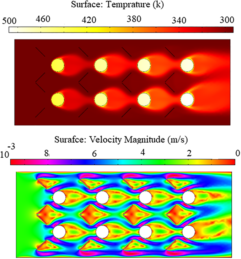
Figure 4: Distribution of temperature and fluid velocity inside the channel with the presence of longer length generators vortex
Fig. 5 shows a diagram of the Nusselt number changes related to these three modes quite clearly. As mentioned in the above sections, the Nusselt number in case three indicates a larger number than in the previous two cases, and in case two it is larger than in case one. The noteworthy point in this diagram is that with increasing the velocity of the fluid, the Reynolds number increases and from a certain velocity onwards it causes the flow to change from slow to turbulent. Initially, due to the transition zone, this change in state causes a decrease in heat transfer, but then again with increasing fluid velocity and subsequently increasing the Reynolds number, the amount of heat transferred increases again. It should be noted that when the generator vortex is added into the channel due to the reduction of the cross-sectional area of the channel through which the fluid passes, the Reynolds number enters the turbulent regions at lower speeds and this negative jump in the Nusselt number in a lower velocity occurs, and in the third case, due to the larger length of the generator vortex and the smaller cross-section of the channel through which the fluid passes, it also occurs at a lower velocity than in the previous two cases.
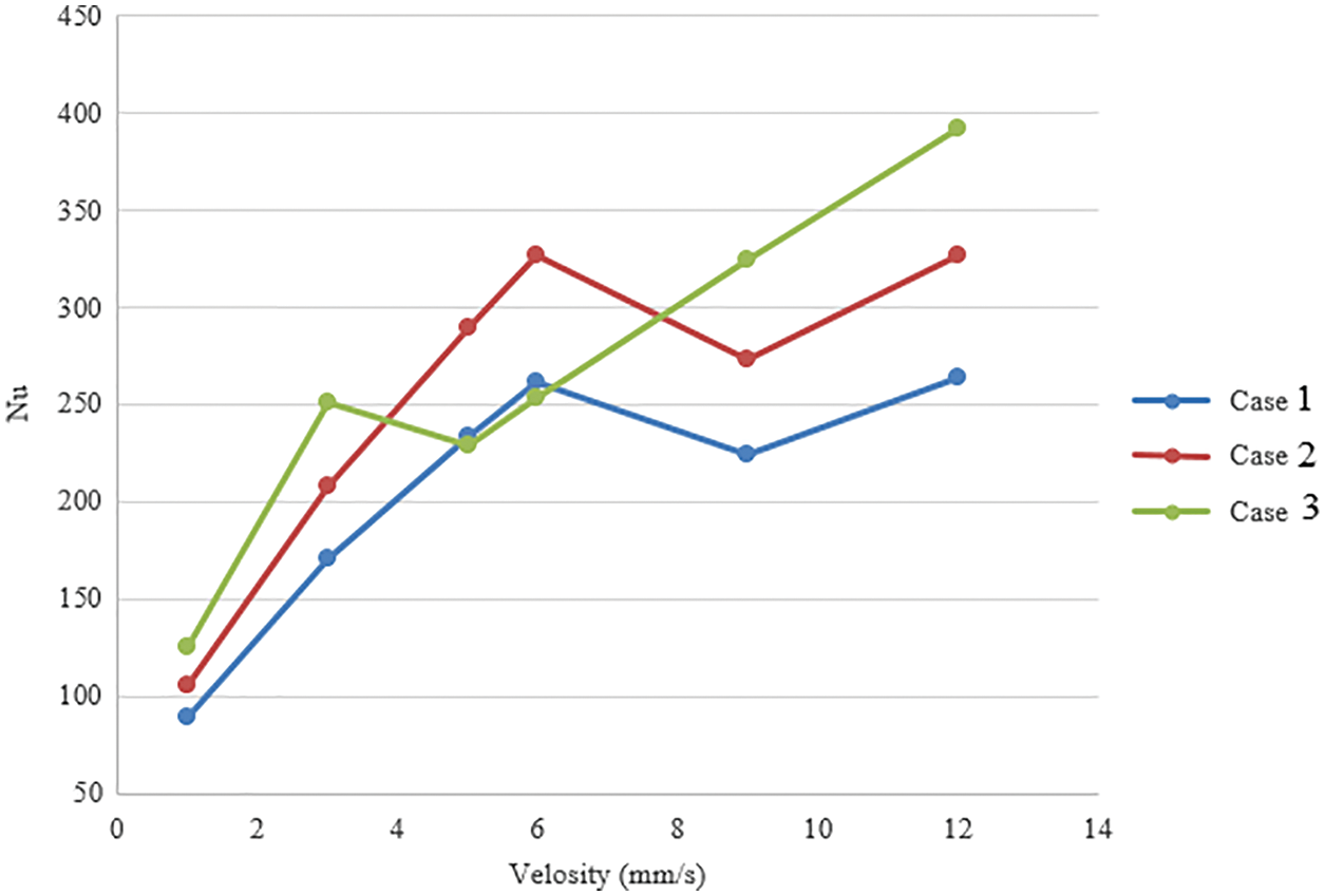
Figure 5: Chart of Nusselt number changes in all three modes
Fig. 6 shows the amount of pressure drop in all three modes from the beginning to the end of the channel. As can be seen from the diagrams, this pressure drop increases with increasing fluid velocity due to the increase in friction between the channel and the fluid. On the other hand, with the addition of generators’ vertex’s, due to the obstacles on the fluid path, this pressure drop is greater in both 2 and 3 cases than in Case 1, and in Case 3, compared to Case 2, due to the larger obstacles, the pressure drop is more.
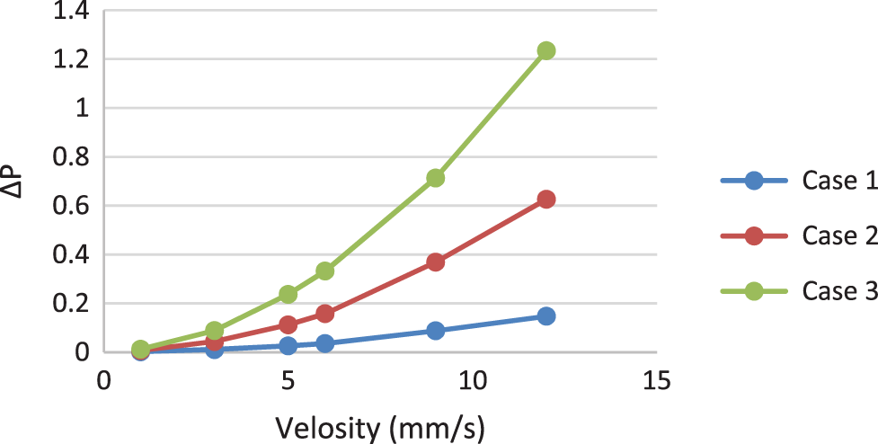
Figure 6: The amount of pressure drop in all three modes from the beginning to the end of the channel
In this paper, by creating the vortex of generators on the fluid motion path and by changing the fluid motion path and directing it to cylindrical cylinders, we try to increase the heat transfer from the cylinders to the fluid flow to reduce the average surface temperature of the cylinders:
With increasing fluid velocity, the amount of heat transfer increases, but this amount does not show a significant number due to the alignment of the cylinders.
Adding the vortex of generators increases heat transfer due to the direction of more excellent fluid around the cylinders.
As the vortex size of the generators increases due to the increase in the transfer of cool fluid around the cylinders, the heat transfer rate also increases significantly.
By adding the vortex of generators and increasing their size, the Reynolds number increases due to reducing the cross-sectional area of the channel through which the fluid flows.
Increasing the Reynolds number due to adding the generators’ vertex if the fluid flow changes from slow to turbulent initially reduces the Nusselt number but return to the uptrend.
In addition to increasing the pressure drop inside the channel due to the increase in fluid velocity, by adding the vertex of the generators, the amount of pressure drop inside the channel is also increased.
Funding Statement: The authors received no specific funding for this study.
Conflicts of Interest: The authors declare that they have no conflicts of interest to report regarding the present study.
References
1. Odugbesan, J. A., Rjoub, H. (2020). Relationship among economic growth, energy consumption, CO2 emission, and urbanization: Evidence from MINT countries. Sage Open, 10(2), 2158244020914648. DOI 10.1177/2158244020914648. [Google Scholar] [CrossRef]
2. Kocijel, L., Poljak, I., Car, Z. (2020). Energy loss analysis at the gland seals of a marine turbo-generator steam turbine. Tehnički Glasnik, 14(1), 19–26. DOI 10.31803/tg-20191031094436. [Google Scholar] [CrossRef]
3. Lin, X., Zhao, Y., Ahmad, M., Ahmed, Z., Rjoub, H. et al. (2021). Linking innovative human capital, economic growth, and CO2 emissions: An empirical study based on Chinese provincial panel data. International Journal of Environmental Research and Public Health, 18(16), 8503. DOI 10.3390/ijerph18168503. [Google Scholar] [CrossRef]
4. Mrzljak, V. (2018). Low power steam turbine energy efficiency and losses during the developed power variation. Tehnički Glasnik, 12(3), 174–180. DOI 10.31803/tg-20180201002943. [Google Scholar] [CrossRef]
5. Zhou, J., Luo, X., Li, C., Lian, L., Wang, G. et al. (2021). Flow boiling heat transfer enhancement under ultrasound field in minichannel heat sinks. Ultra Sonics Sono Chemistry, 78(7–8), 105737. DOI 10.1016/j.ultsonch.2021.105737. [Google Scholar] [CrossRef]
6. Wu, J. T., Chen, Q. C., Sun, K. L., Zhang, Y. J. (2021). Phase change material heat transfer enhancement in latent heat thermal energy storage unit with single fin: Comprehensive effect of position and length. Journal of Energy Storage, 42, 103101. DOI 10.1016/j.est.2021.103101. [Google Scholar] [CrossRef]
7. Dang, W., Wang, L. B. (2021). Convective heat transfer enhancement mechanisms in circular tube inserted with a type of twined coil. International Journal of Heat and Mass Transfer, 169(4), 120960. DOI 10.1016/j.ijheatmasstransfer.2021.120960. [Google Scholar] [CrossRef]
8. Nourdanesh, N., Hossainpour, S., Esmaeilzadeh, E. (2019). Experimental investigation of heat transfer enhancement in an open-channel flow with dielectric fluid using electrohydrodynamic conduction pumps concept. Applied Thermal Engineering, 157, 113711. DOI 10.1016/j.applthermaleng.2019.04.121. [Google Scholar] [CrossRef]
9. Wang, S. L., Zhu, J. F., An, D., Zhang, B. X., Chen, Y. R. et al. (2023). Heat transfer enhancement of symmetric and parallel wavy microchannel heat sinks with secondary branch design. International Journal of Thermal Sciences, 171, 107229. DOI 10.1016/j.ijthermalsci.2021.107229. [Google Scholar] [CrossRef]
10. Li, N., Wang, J., Klemeš, J. J., Wang, Q., Varbanov, P. S. et al. (2021). A target-evaluation method for heat exchanger network optimisation with heat transfer enhancement. Energy Conversion and Management, 238(8), 114154. DOI 10.1016/j.enconman.2021.114154. [Google Scholar] [CrossRef]
11. Xin, F., Yu, M., Liu, W., Liu, Z. (2021). Heat transfer characteristics of enhanced cooling tube with a helical wire under oscillatory flow in Stirling engine. International Journal of Thermal Sciences, 168(6), 107063. DOI 10.1016/j.ijthermalsci.2021.107063. [Google Scholar] [CrossRef]
12. Xie, P., Zhang, X. (2019). A method of rib-bed plate enhancing heat transfer in hydrogen rocket engine chamber wall. International Journal of Hydrogen Energy, 44(36), 20504–20515. DOI 10.1016/j.ijhydene.2019.06.041. [Google Scholar] [CrossRef]
13. Nourdanesh, N., Esmaeilzadeh, E. (2013). Experimental study of heat transfer enhancement in electrohydrodynamic conduction pumping of liquid film using flush electrodes. Applied Thermal Engineering, 50(1), 327–333. DOI 10.1016/j.applthermaleng.2012.08.038. [Google Scholar] [CrossRef]
14. Izadi, A., Siavashi, M., Rasam, H., Xiong, Q. (2020). MHD enhanced nanofluid mediated heat transfer in porous metal for CPU cooling. Applied Thermal Engineering, 168(30), 114843. DOI 10.1016/j.applthermaleng.2019.114843. [Google Scholar] [CrossRef]
15. Zharfa, M., Karimi, N. (2021). Intensification of MILD combustion of methane and hydrogen blend by the application of a magnetic field–A numerical study. Acta Astronautica, 184, 259–268. DOI 10.1016/j.actaastro.2021.04.023. [Google Scholar] [CrossRef]
16. Wang, X., Pan, W. (2022). Numerical simulation of wake vortices generated by an A330-200 Aircraft in the nearfield phase. Fluid Dynamics & Materials Processing, 18(1), 173–188. DOI 10.32604/fdmp.2022.017869. [Google Scholar] [CrossRef]
17. Roozitalab, A. (2022). Employing strategic management to study the effect of brand awareness on customer’s loyalty: Exploring the mediation effect of perceived brand quality and brand communication: A study of Samsung Electronics Company in Tehran branch. SMART Journal of Business Management Studies, 18(1), 38–46. DOI 10.5958/2321-2012.2022.00005.7. [Google Scholar] [CrossRef]
18. Nourdanesh, N., Hossainpour, S., Adamiak, K. (2020). Numerical simulation and optimization of natural convection heat transfer enhancement in solar collectors using electrohydrodynamic conduction pump. Applied Thermal Engineering, 180(12), 115825. DOI 10.1016/j.applthermaleng.2020.115825. [Google Scholar] [CrossRef]
19. Wayne, L., Staats, J. G. (2015). Active heat transfer enhancement in air cooled heat sinks using integrated centrifugal fans. International Journal of Heat and Mass Transfer, 82, 189–205. DOI 10.1016/j.ijheatmasstransfer.2014.10.075. [Google Scholar] [CrossRef]
20. Pustokhina, I., Seraj, A., Hafsan, H., Mostafavi, S. M., Alizadeh, S. M. (2021). Developing a robust model based on the gaussian process regression approach to predict biodiesel properties. International Journal of Chemical Engineering, 2021, 12. DOI 10.1155/2021/5650499. [Google Scholar] [CrossRef]
21. Man, Z., Ebadi, A. G., Mostafavi, S. M., Surendar, A. (2019). Fuel oil characteristics and applications: Economic and technological aspects. Petroleum Science and Technology, 37(9), 1041–1044. DOI 10.1080/10916466.2019.1570256. [Google Scholar] [CrossRef]
22. Qu, G., Yue, T., Zhang, X., Wei, S. (2022). How do water filled traffic barriers shake a suspension bridge? Fluid Dynamics & Materials Processing, 18(3), 591–608. DOI 10.32604/fdmp.2022.017776. [Google Scholar] [CrossRef]
23. Fard, G. P., Sabzi, R. E. (2018). Multiwall carbon nanotube paste electrode as a sensor for sensitive determination of deferasirox in the presence of uric acid: Application for the analysis of pharmaceutical and biological samples. Turkish Journal of Chemistry, 42(2), 493–504. [Google Scholar]
24. Jalilpour, Y., Abdollahzade, B., ParviziFard, G., Aghazadeh, M., Bialvaei, A. Z. et al. (2017). A simple route for preparation of pH-sensitive hydrogels by using egg white proteins in alginate scaffold for the encapsulation of probiotics. ARS Pharmaceutica, 58(3), 127–136. [Google Scholar]
25. Salakhov, R., Gabdulkhakova, E. (2020). Numerical and experimental study of the impeller of a liquid pump of a truck cooling system and the development of a new open-type impeller. Tehnički Glasnik, 14(2), 135–142. DOI 10.31803/tg-20200309115417. [Google Scholar] [CrossRef]
26. Jeong, M., Ha, M. Y., Park, Y. G. (2019). Numerical investigation of heat transfer enhancement in a dimpled cooling channel with different angles of the vortex generator. International Journal of Heat and Mass Transfer, 144(9), 118644. DOI 10.1016/j.ijheatmasstransfer.2019.118644. [Google Scholar] [CrossRef]
27. Wang, H. D., Wang, H., Gao, F., Zhou, P. Z., Zhai, Z. Q. (2018). Literature review on pressure-velocity decoupling algorithms applied to built-environment CFD simulation. Building and Environment, 143(2), 671–678. DOI 10.1016/j.buildenv.2018.07.046. [Google Scholar] [CrossRef]
28. Zhou, P., Wang, H., Dai, Y., Huang, C. (2022). Performance evaluation of different pressure-velocity decoupling schemes in built environment simulation. Energy and Buildings, 257, 111763. DOI 10.1016/j.enbuild.2021.111763. [Google Scholar] [CrossRef]
 | This work is licensed under a Creative Commons Attribution 4.0 International License, which permits unrestricted use, distribution, and reproduction in any medium, provided the original work is properly cited. |