DOI:10.32604/iasc.2020.010798
| Intelligent Automation & Soft Computing DOI:10.32604/iasc.2020.010798 | |
| Article |
Sliding-Mode Control of Unmanned Underwater Vehicle Using Bio-Inspired Neurodynamics for Discrete Trajectories
1Information Engineering College, Shanghai Maritime University, Shanghai, 200135, China
2Shanghai Engineering Research Center of Intelligent Maritime Search/Rescue and Underwater Vehicles, Shanghai Maritime University, Shanghai, 200135, China
3The Collective Intelligence and Bionic Robotics Laboratory, Robotics Engineering, Worcester Polytechnic Institute, Worcester, MA, 01609-2280, USA
*Corresponding Author: Zhigang Deng. Email: dzg1026@126.com
Received: 04 October 2019; Accepted: 30 July 2020
Abstract: Trajectory tracking control can be considered as one of the main researches of unmanned underwater vehicles (UUV). The bio-inspired neurodynamics model was used to make the output continuous and smooth for the inflection points to deal with the speed jump of the conventional tracking controller for discrete trajectories. A horizon-plane trajectory tracking control law is designed using the bio-inspired neurodynamics model and sliding-mode method without chattering. Finally, the simulation of the mentioned two methods is compared with the results showing this as effective and feasible.
Keywords: Bio-inspired neurodynamics; discrete trajectory; slide-mode control; trajectory tracking; unmanned underwater vehicles (UUV)
Unmanned underwater vehicles (UUV) have been widely utilized in the academic fields, oil and gas industries, and military applications. Trajectory following control using minimum position sensors and modern control strategies is an essential problem for UUV. Due to the complexity and unpredictability of the underwater and under-actuated environment, powerful coupling and nonlinear features of UUV make UUV’s tracking control a very challenging research area.
In the real word, most trajectories are made of discrete lines and some path planning algorithms generate the discrete trajectories. Conventional trajectory-tracking controller can only deal with continuously differentiable trajectories. Because of the non-holonomic constraints, the conventional solution produces discontinuous velocities with discrete trajectories, which is impossible in practice. Therefore, the study of tracking control for the discrete trajectory is an important issue in practice. We propose a novel control method by adding a neural system to solve the problems in tracking discrete trajectories.
Various works have been devoted to tracking control in the last decade, including traditional adaptive control [1,2], sliding-mode control [3–7], backstep control [8–10], neural-network control [11–13], and fuzzy control [14–16].
Since the calculation of the hydrodynamics forces is complicated, the UUV control using classic model-based approaches is impossible. Due to its prominent advantages, including robustness to parametric uncertainties and satisfactory disturbance rejection capability, the sliding-mode control (SMC) is known as one of the popular control strategies employed in robust tracking control of mobile robots and UUV. Nevertheless, high fluctuations in its control signal, called the chattering phenomenon, is its essential deficiency [3,4], leading to significant heat losses in electrical power circuits and early destroying of actuators. Besides, it can stimulate high-frequency unmodeled components, affecting the controller efficiency.
The back stepping control approach has been utilized in mobile robots and UUV. The essential principle of this control strategy is to construct a simple velocity controller for Lyapunov-based stabilization of the closed-loop system. Although significant initial state errors can be compensated through the mentioned approach, its drawback is completely evident: The state errors can considerably affect the velocity control law, leading to significant velocities in major initial error situations and sudden speed variations induced by abrupt tracking errors. Accordingly, the control actions may exceed their permissible values at abrupt velocity changes.
To clarify the drawbacks of conventional model-based control approaches, SMC, and the back stepping approach, neural networks have been utilized by various controllers to provide more suitable control actions. Accordingly, there is no need for accurate modeling of underwater vehicles. Moreover, thruster and vehicle nonlinearities can be better described. However, to enhance the UUV performance, the online or offline tuning algorithm is inevitable in the mentioned neural network model, which can be considered as an essential drawback for these tracking control systems. The high computational load of this tuning algorithm procedure confines its application in actual plants.
Fuzzy tracking control strategies have a simple calculation algorithm that does not require online or offline tuning. Although the mentioned control strategies can compensate for the significant initial velocities effect, an empirical knowledge with trial and error is required to determine the fuzzy rules. In addition to the mentioned control strategies, several approaches have been presented for UUV control, including the feedback linearization technique [17–19], and  control [20,21] Selecting a comprehensive control approach among all the approaches mentioned above for resolving each of the mentioned issues for UUV is challenging.
Due to the shunting features of the bio-inspired neurodynamic model [10,22], the output of the bio-inspired neurodynamic model is confined to a limited range and smoothed without any abrupt changes under sudden input variations. The hybrid controller using the bio-inspired model [10,23] have two major limitations: the tracking trajectory is continuous, not discrete, and the only one bio-inspired neurodynamic was constructed to make the velocity controller output smooth, and prevent abrupt changes of underwater vehicles and meet the thruster control limitation for the initial stage. The current research deals with the issue of abrupt changes in UUV for all tracking process, and two biological neural models are employed to design the tracking controller, and the speed in all dimensions is described through a shunting relation to make the output continuous and smooth for the inflection points. Therefore, a kinematic system integrating the SMC and two bio-inspired neurodynamic models are presented for tracking control of the discrete trajectory.
The rest of the current work is organized as the following. The kinematic model of UUV is introduced in Section 2. Section 3 discusses the SMC principles. We present the bio-inspired neurodynamic model in Section 4. In Section 5, we design a neural dynamics full-state SMC for discrete trajectories. The algorithm simulations are given in Section 6. In the last section, we conclude the paper and discuss the future scope of improvement.
To make research for the UUV, we often build two frames: inertial and body-fixed frames (see Fig. 1) shows. There are six degrees of freedom (DOF), including surge, sway, heave, roll, pitch, and yaw.  denotes the spatial velocity state vector of UUV along with the body-fixed frame, and
  defines the position and direction state vector along with the inertial frame.
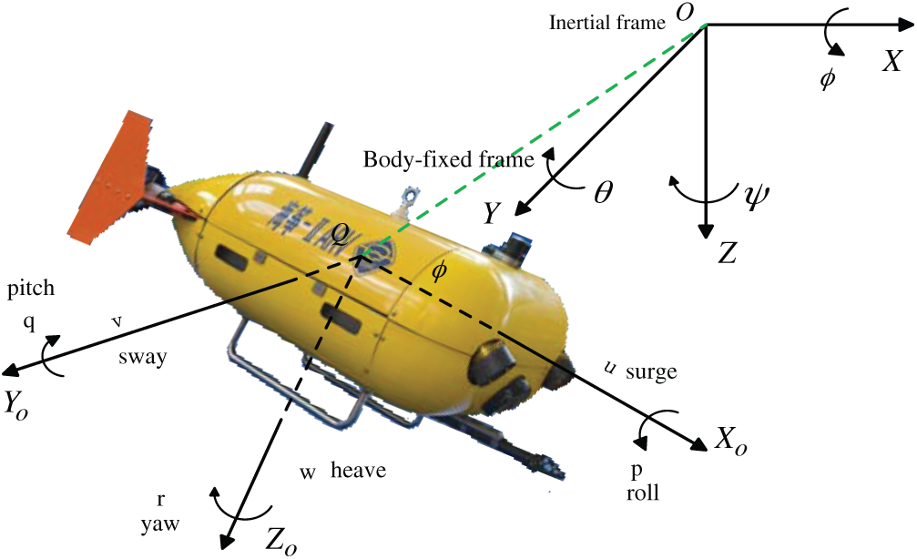
Figure 1: The UUV (Sea-Kite II) coordinate system
According to the thruster distribution of UUV (Sea-Kite II), there are only 4 DOF: Surge, heave, pitch and yaw. For horizon-plane motion control, without lateral force, there are 2 DOFs: Surge and yaw, we could get the non-holonomic constraints as follows [24],

To realize the trajectory tracking control, UUV must track a predefined trajectory in the Cartesian workspace with a definite timing rule. The desired trajectory satisfies the UUV non-holonomic constraint. Equivalently, it tracks a trajectory generated by a reference UUV (Fig. 2).
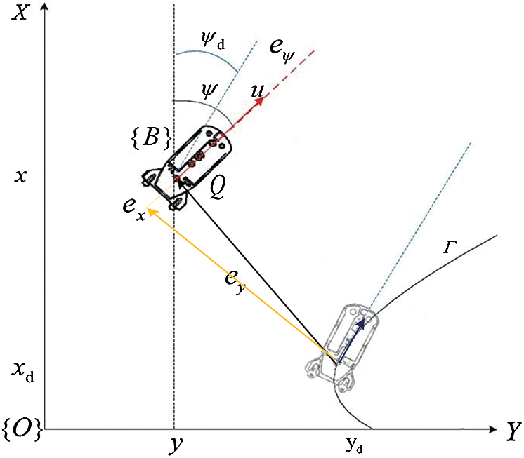
Figure 2: Tracking error in body coordinate frame of underwater vehicle
To attain the horizontal plane motion control of the UUV, the reference state of the vehicle in the inertial frame is defined as  ,
,  describes the velocity controller output in the body-fixed frame, and the actual state of UUV is represented by
 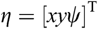 . For horizon-plane motion control of Sea-kite II, the UUV’s kinematic model is described as:
The motion tracking issue of the UUV is defined as the following: Under the non-holonomic constraints ( ), design a control law to generate the bounded control input
  to force the UUV to move, such that the state errors
  tend to zero.
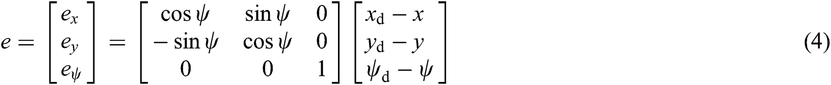
The state errors in the body frame are denoted by  . Here,
  denotes the path following error in the inertial frame.
  is the conversion function from the body-fixed frame to the inertial one for the position and orientations.
The equivalent path following error in the body-fixed frame is described as
The tracking controllers are designed to enforce the UUV to follow the desirable path by setting the surge and yaw motion speed and tend the state errors  to zero.
According to the relevant deduction [25], we could get
when  , consider Lyapunov function

Using  , taking the time derivative of Eq. (6), it yields

From the lemma 1 [8], one obtains  , (only when equality constraint is satisfied for
  ), then
  , so we could make the conclusion that only
  converges to zero and
  converges to
  , then the system converges to zero.
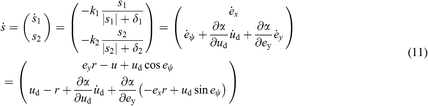
Based on the conclusion, the following sliding surfaces are proposed [3]:

Through designing the SMC to realize  ,
,  ,
,  and
and  converge to zero and
  , respectively, then it yields
  ,
,  .
.
The reaching law of equal speed is chosen as

To decrease the chattering phenomenon, the sign function is replaced with the following continuous function.

where  describes the positive decimal fraction.
Using  , according to Eq. (5) and Eq. (8), it yields
After some algebraic operations, one obtains the control law
where  ,
, 
4 The Bio-Inspired Neurodynamic Model
To overcome the abrupt velocity changes and the control limitation issue, a bio-inspired neurodynamic model is incorporated with the virtual velocity controller. Due to the bio-inspired neurodynamic model’s shunting features, it is confined to a specific range and kept smooth without any sudden changes under abrupt input changes, leading to a considerable improvement in the controller efficiency.
The bio-inspired neurodynamic model has been initially constructed by Grossberg [26]. This model can represent the real-time adaptive treatment of humans. It has been initially extracted using the membrane model developed by Hodgkin et al. [27] for a membrane patch based on electrical components. The membrane model can describe the voltage dynamics through the membrane with the following state-space equations
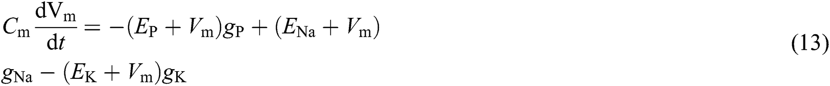
where the membrane capacitance is denoted by  . The Nernst potentials for potassium and sodium ions, and the passive leak current in the membrane can be described through coefficients
  ,
,  , and
, and  , respectively.
  ,
,  , and
, and  describe the conductances of the potassium, sodium, and passive channels, and depend on the time-varying input signals.
By using  ,
,  ,
,  ,
,  ,
,  ,
,  and
and  , the following shunting relation can be obtained

where  indicates the regular activity (membrane potential) of the neuron. The passive decay rate and the upper and lower bounds of the neural and inhibitory input are denoted by coefficients
  ,
,  , and
, and  , respectively. The shunting dynamics of a single neuron can be described using the mentioned relation. The neutron dynamics are confined to a finite range
  with automatic gain control. Thus, the following shunting expression can be obtained:

where  and
and  . In a system with properly selected inputs, several desired functional features like competition, short-term memory, and upper and lower bounds can be extracted from the model. The shunting model can be described with an appropriate differential equation.
It is ensured that the system output  will be retained in the interval
  for all excitatory and inhibitory inputs. It is continuous and smooth. Various benefits, including insured stability and computational performance, can be attained via the bio-inspired neurodynamic model for the UUV path following control. The bio-inspired neurodynamic model gives a smooth velocity response regarding the path following errors.
5 Control Strategy for Underwater Vehicles
To obtain continuous and practical outputs, two biological neural models are employed to design the tracking controller, and the velocity for any dimension can be described by a shunting relation. It can generate smooth velocity signals under sudden turns.
The structure of the presented neural dynamics based controller is shown in Fig. 3.  is the desired discrete trajectory to track and
  is the current state (including position and orientation). From the controller diagram, the proposed model includes two components. The first is the neural system, which can produce smooth velocity
  and accurate virtual tracking trajectory
  . The errors
  between
  and
and  are the inputs for the first bio-inspired neurodynamic model. The produced virtual trajectory still consists discrete trajectories without considering the non-holonomic constraints of the UUV.
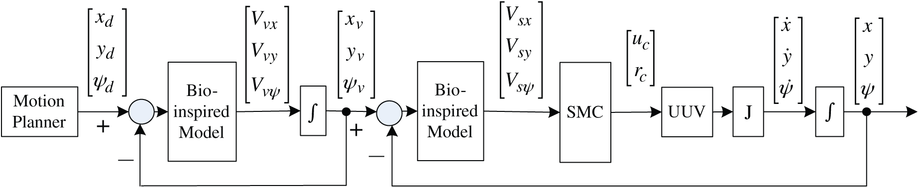
Figure 3: Scheme of the proposed control system for underwater vehicles
In the second part of the proposed model, the UUV’s non-holonomic property is considered in the tracking controller to satisfy the special requirement. A second neural system is added to generate smooth virtual velocity  , which consists of the SMC inputs. Besides, the errors
  between
  and
and  describe the input for the second bio-inspired neurodynamic model. Then we could obtain the desired surge and yaw speed input
  for the UUV by sliding-mode controller. Through the UUV kinematic model and the conversion function
  and the integrated process, we get the actual position and orientation of the UUV.
The  axis and
  axis velocities and angular velocity are represented by the shunting relations. Using the shunting equation discussed above, the following velocity dynamics can be derived
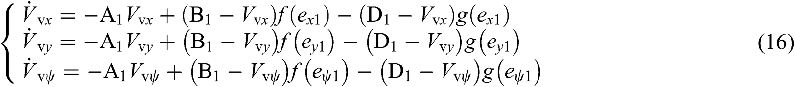
where  ,
,  ,
,  ,
,  , and
, and  , Similarly, to obtain other variables, Eq. (3.2) could be integrated to get a virtual trajectory
  °
°
The output  of the second biological neural model can be obtained in terms of the shunting model as
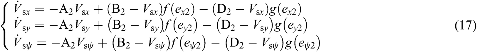
where  ,
,  ,
,  ,
,  and
and  .
.
We obtain other variables similarly.
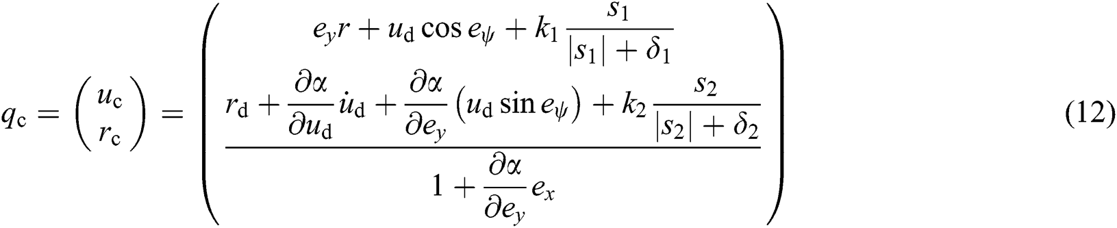
Using the virtual output  to replace the error
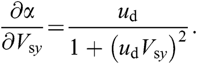
  in Eq. (12), we obtain the control output of SMC given in Eq. (18)
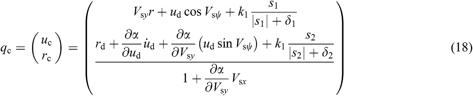
where 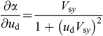 ,
, 
To evaluate the accuracy of the algorithms of bio-inspired control in comparison with the SMC for underwater vehicles, the two methods are simulated in MATLAB R2018b on a computer with Intel Core i7 CPU and a dominant frequency of 2.7 GHz with 8 GB RAM. We compare the bio-inspired control approach with the sliding-mode control method, including two cases: poly-line trajectory tracking and trapezoid-line trajectory tracking. The simulations are accomplished to clarify the benefits of the designed controller in tending an underwater to a predefined path.
The focus of the current study is on a discrete trajectory, which indicates that the path is discontinuous and does not satisfy the non-holonomic constraints. The fundamental issue we solve here is the sharp jumps from the initial state errors and the discontinuity when there are sharp turns in the desirable path.
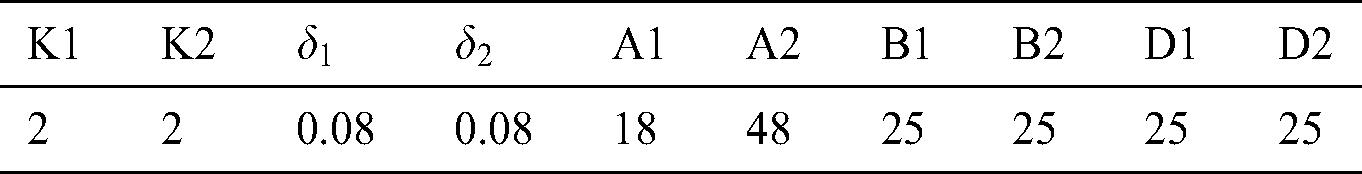
In the current section, a poly-line trajectory with two rotations is considered to clarify the efficiency of the presented neural dynamics-based full-state tracking controller. Tab. 1 gives the controller parameters.
Table 1: The controller parameters
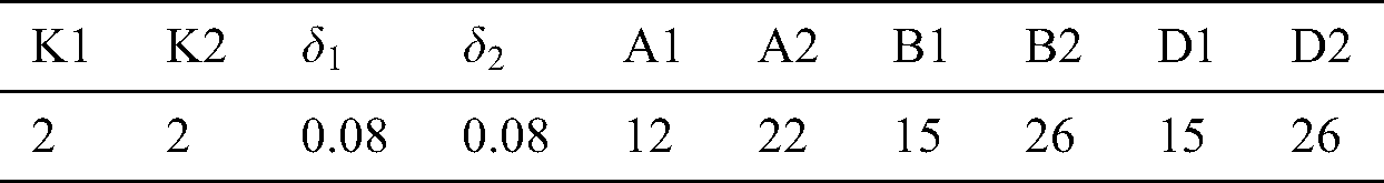
The discrete trajectory includes three lines. The initial and final points in the Cartesian coordinate are located at (1, 1) and (5, 7), respectively. The initial orientation of the discrete path is chosen as 45°. At points (3, 3) and (3, 5), the direction of the discrete path is changed from 45° to 90° and from 90° to 45°, respectively. The UUV is initially located at (0.5, 0), with the direction at 0°. The UUV begins with position and direction errors (0.5, 1) and 45°, respectively. Moreover, the UUV has two 45°direction variations at points (3, 3) and (3, 5). As shown in Fig. 4, for the bio-inspired controller, at both rotating points, the UUV has position offsets from the predefined path such that the real path can meet the non-holonomic limitations; while for the path following performed by the SMC, the non-holonomic limitations are not fulfilled, generating discontinuous velocities. It indicates that more deviations from the desirable trajectory can be found at rotating points than the corresponding ones in the presented controller. The current states of UUV while tracking Poly-line trajectory using two methods are presented in Fig. 5.
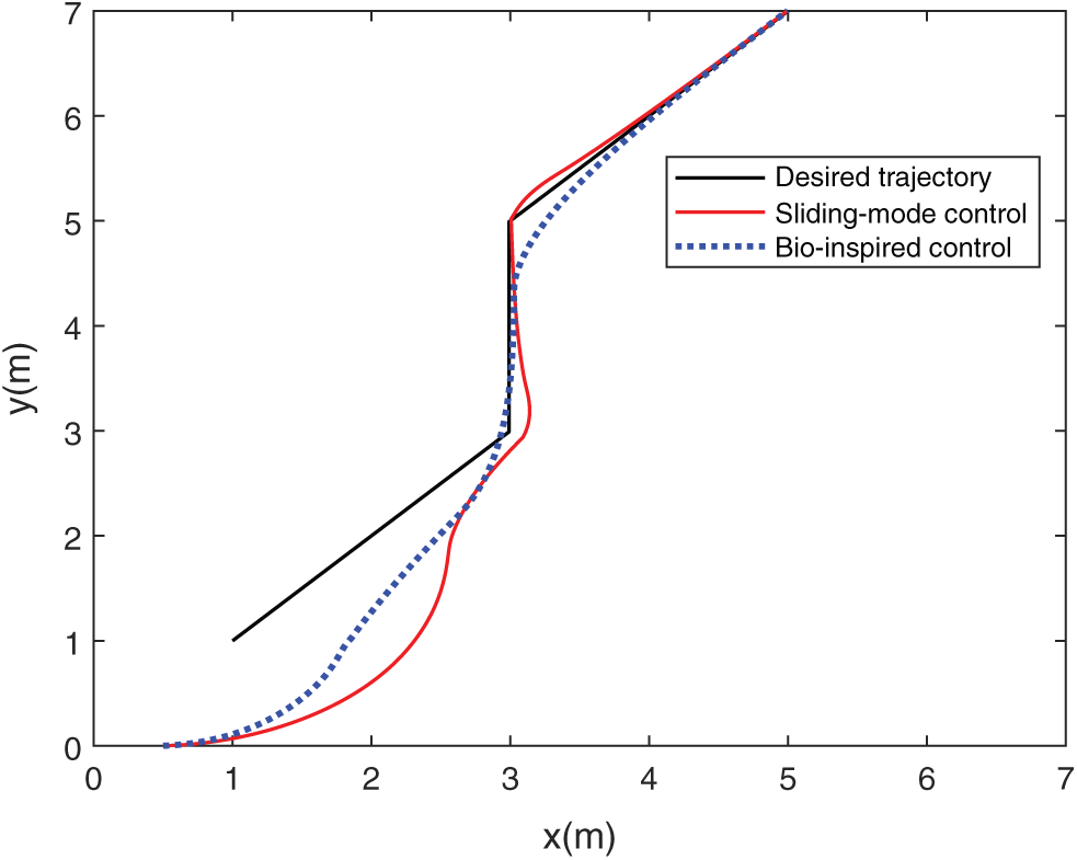
Figure 4: The UUV’s trajectories while tracking Poly-line trajectory using two methods
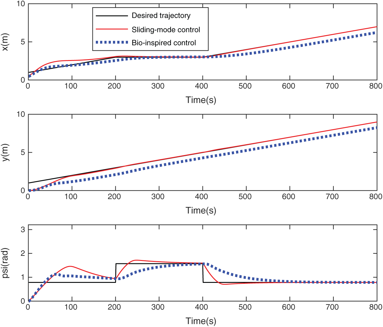
Figure 5: The current states of UUV while tracking Poly-line trajectory using two methods
Besides, it can be observed from Fig. 6 that for the proposed controller, the UUV begins quickly to catch up with the desirable path, the forward and angular velocities grow slowly and smoothly at the start point. At two rotating points, the UUV’s orientation varies slowly and smoothly without abrupt changes. For the remainder of the trajectory following, the UUV drives with an extremely stable velocity. While for the other method, the controller generates discontinuous angular velocities at two rotating points, and the angular velocities vary from 0 to 3.1 rad/s and 0 to −3.3 rad/s, respectively.
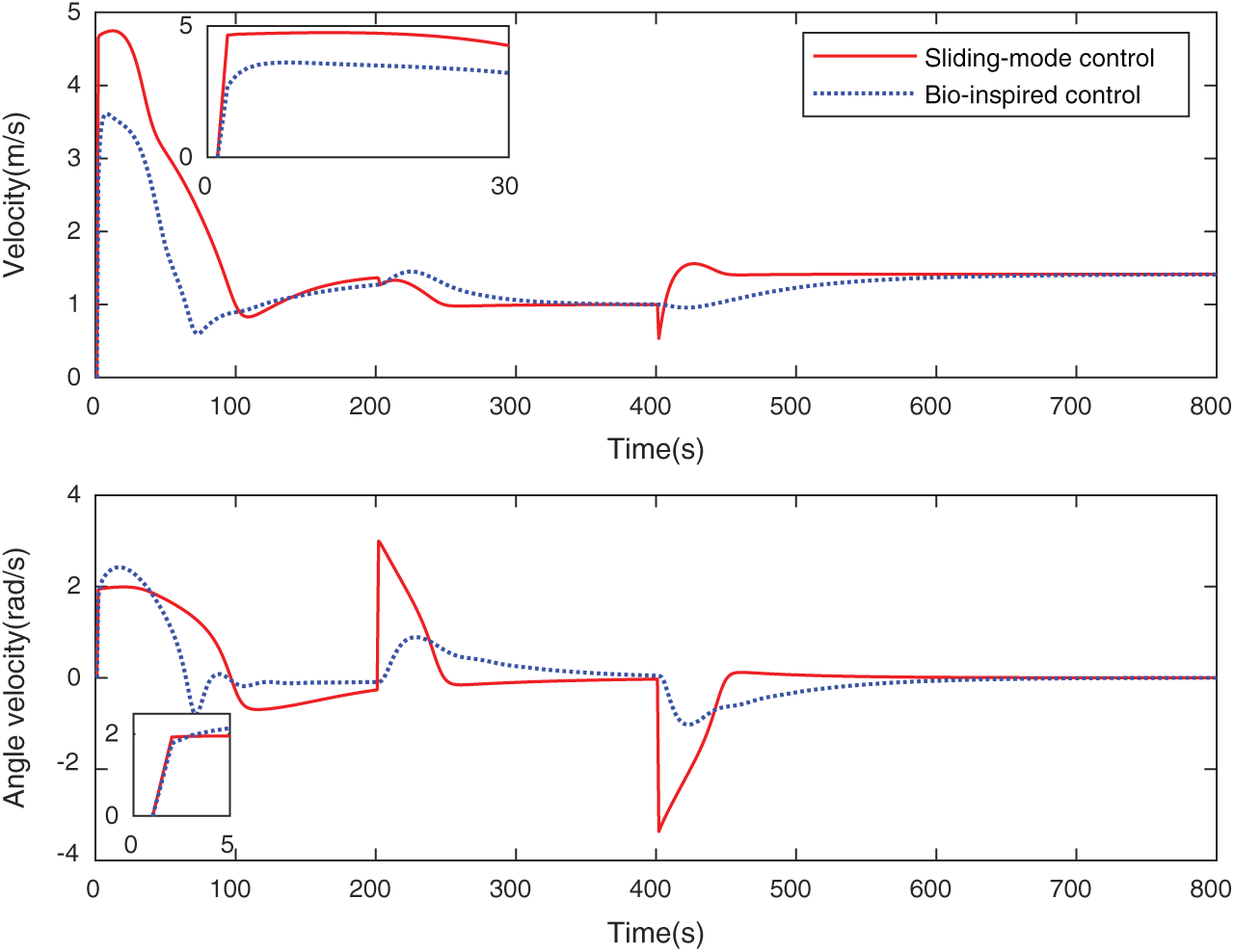
Figure 6: The state of the UUV while tracking Poly-line trajectory
6.2 Poly-line Trajectory Tracking
In the current section, a trapezoid-line trajectory with four rotations is simulated to demonstrate the efficiency of the presented neural dynamics-based full-state path following controller. Tab. 2 presents the controller parameters.
Table 2: The controller parameters
The discrete trajectory includes four lines. The initial and final points lie at (1, 1) and (6.2, 1) in the Cartesian coordinate, respectively. The initial orientation of the discrete trajectory is considered as 0°. At points (7, 1), (5, 3), (3, 3) and (1, 1), the discrete trajectory changes its orientation for four times. The UUV’s initial location is (0, 0.5), with the direction at 0°. The UUV begins with position and direction errors as (1, 0.5) and 0°, respectively. As presented in Fig. 7, for the bio-inspired controller, at both turn points, the UUV’s position deviates from the desirable path such that the real trajectory can fulfill the non-holonomic limitations, while the SMC can follow the trajectory without the satisfaction of the non-holonomic constraints, which leads to discontinuous velocities. It can be concluded that the UUV has more significant offsets from the desirable trajectory at rotating points than the corresponding ones in the presented controller. The current states of UUV while tracking the Trapezoid-line trajectory using two methods are shown in Fig. 8.
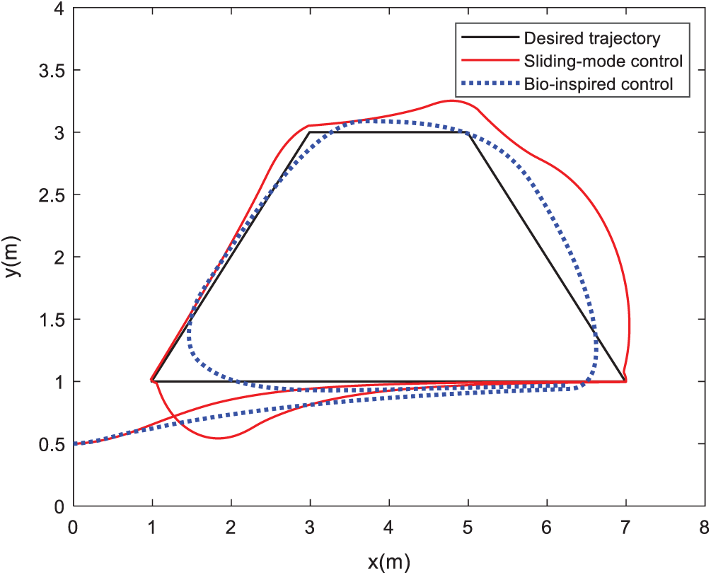
Figure 7: The trajectories of UUV while tracking Trapezoid-line trajectory using two methods
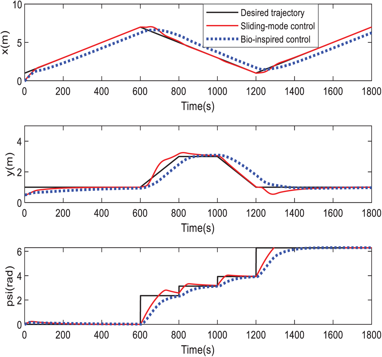
Figure 8: The current states of UUV while tracking Trapezoid-line trajectory using two methods
Also, as presented in Fig. 9, for the designed controller, the UUV begins quickly to reach the desired trajectory. The forward and angular velocities grow steadily and smoothly at the starting point. At two rotating points, the UUV’s direction is varied slowly and smoothly without sudden changes. For the remaining of the trajectory following, the UUV drives at an enormously stable velocity. While for the other method, the controller causes discontinuous angular velocities at four rotating points, and the angular velocities vary from 0 to 3.1 rad/s, 0 to 1 rad/s, 0 to 1.5 rad/s, and 0 to 2.8 rad/s, respectively.
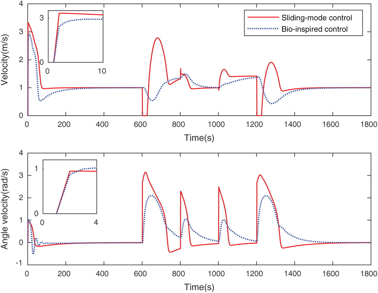
Figure 9: The state of UUV while tracking Trapezoid-line trajectory
Therefore, we conclude that the designed controller produces extremely smooth forward and angular velocities without any sudden changes and discontinuities in the entire path following process.
In the current work, the path following using the SMC approach and the bio-inspired neurodynamic model was proposed to make the output continuous and smooth for the inflection points. The simulation of the plane trajectory tracking control was presented under different discrete trajectories. From the simulation results, the designed control system shows stability and robustness clearly. The verification experiment in the pool will be carried out in the future. Moreover, to cope with actual conditions, ocean currents should be considered.
Funding Statement: The current study was supported by the National Natural Science Foundation of China (51839004), International Academic Cooperation and Exchange Project of Shanghai under grant number 18550720100 and Capacity Building Project of Shanghai Local Colleges and Universities under grant 1904050160.
Conflicts of Interest: The authors declare that they have no conflicts of interest to report regarding the present study.
1. G. Antonelli, F. Caccavale and S. Chiaverini. (2003). “A novel adaptive control law for underwater vehicles,” IEEE Transactions on Control Systems Technology, vol. 11, no. 2, pp. 221–232. [Google Scholar]
2. B. K. Sahu and B. Subudhi. (2014). “Adaptive tracking control of an autonomous underwater vehicle,” International Journal of Automation and Computing, vol. 11, no. 3, pp. 299–307. [Google Scholar]
3. T. Ye, Z. Hou, M. Tan, L. Li and X. Chen. (2004). “Sliding mode trajectory tracking control of mobile robots,” Chinese High Technology Letters, vol. 14, no. 1, pp. 71–74. [Google Scholar]
4. S. Serdar, J. B. Bradley and P. P. Ron. (2008). “A chattering-free sliding-mode controller for underwater vehicles with fault-tolerant infinity-norm thrust allocation,” Ocean Engineering, vol. 35, no. 16, pp. 1647–1659. [Google Scholar]
5. J. Guerrero, J. Torres, V. Creuze and A. Chemori. (2019). “Trajectory tracking for autonomous underwater vehicle: An adaptive approach,” Ocean Engineering, vol. 172, no. 1, pp. 511–522.
6. E. Zakeri, S. A. Moezi and M. Eghtesad. (2019). “Optimal interval type-2 fuzzy fractional order super twisting algorithm: A second order sliding mode controller for fully-actuated and under-actuated nonlinear systems,” ISA Transactions, vol. 85, pp. 13–32.
7. Z. Yan, M. Wang and J. Xu. (2019). “Robust adaptive sliding mode control of underactuated autonomous underwater vehicles with uncertain dynamics,” Ocean Engineering, vol. 173, no. 2, pp. 802–809. [Google Scholar]
8. W. Wu, H. Chen and Y. Wang. (2001). “Global trajectory tracking control of mobile robots,” Acta Automatica Sinica, vol. 27, no. 3, pp. 326–331. [Google Scholar]
9. L. Lapierre and B. Jouvencel. (2008). “Robust nonlinear trajectory-following control of an AUV,” IEEE Journal of Oceanic Engineering, vol. 33, no. 2, pp. 89–102.
10. B. Sun, D. Zhu and S. X. Yang. (2014). “A Bioinspired filtered backstepping tracking control of 7000-m manned submarine vehicle,” IEEE Transactions on Industrial Electronics, vol. 61, no. 7, pp. 3682–3693. [Google Scholar]
11. Z. Peng and J. Wang. (2018). “Output-feedback path-following control of autonomous underwater vehicles based on an extended state observer and projection neural networks,” IEEE Transactions on Systems, Man, and Cybernetics: Systems, vol. 48, no. 4, pp. 535–544. [Google Scholar]
12. Z. Gao and G. Guo. (2018). “Adaptive formation control of autonomous underwater vehicles with model uncertainties: Adaptive formation control,” International Journal of Adaptive Control and Signal Processing, vol. 32, no. 7, pp. 1067–1080.
13. J. Cui, L. Zhao, J. Yu, C. Lin and Y. Ma. (2019). “Neural network-based adaptive finite-time consensus tracking control for multiple autonomous underwater vehicles,” IEEE Access, vol. 7, pp. 33064–33074. [Google Scholar]
14. E. Zakeri, S. Farahat, S. A. Moezi and A. Zare. (2016). “Path planning for unmanned underwater vehicle in 3D space with obstacles using spline-imperialist competitive algorithm and optimal interval type-2 fuzzy logic controller,” Latin American Journal of Solids and Structures, vol. 13, no. 6, pp. 1054–1085. [Google Scholar]
15. X. Xiang, C. Yu and Q. Zhang. (2017). “Robust fuzzy 3D path following for autonomous underwater vehicle subject to uncertainties,” Computers & Operations Research, vol. 84, no. 1, pp. 165–177.
16. X. Liu, M. Zhang and E. Rogers. (2019). “Trajectory tracking control for autonomous underwater vehicles based on fuzzy re-planning of a local desired trajectory,” IEEE Transactions on Vehicular Technology, vol. 68, no. 12, pp. 11657–11667. [Google Scholar]
17. L. X. Pan, H. Z. Jin and L. L. Wang. (2011). “Robust control based on feedback linearization for roll stabilizing of autonomous underwater vehicle under wave disturbances,” China Ocean Engineering, vol. 25, no. 2, pp. 251–263. [Google Scholar]
18. R. A. S. Fernandez, E. A. P. R. Z. Milosevic, S. Dominguez and C. Rossi. (2019). “Nonlinear attitude control of a spherical underwater vehicle,” Sensors (Basel), vol. 19, no. 6, pp. 1–20.
19. M. Asif, A. Y. Memon and M. J. Khan. (2015). “Output feedback control for trajectory tracking of wheeled mobile robot,” Intelligent Automation & Soft Computing, vol. 22, no. 1, pp. 75–87. [Google Scholar]
20. J. Petrich and D. J. Stilwell. (2011). “Robust control for an autonomous underwater vehicle that suppresses pitch and yaw coupling,” Ocean Engineering, vol. 38, no. 1, pp. 197–204. [Google Scholar]
21. L. L. Wang, H. J. Wang and L. X. Pan. (2015). “H∞ control for trajectory tracking of autonomous underwater vehicle motion,” Advances in Mechanical Engineering, vol. 7, no. 5, pp. 1–18. [Google Scholar]
22. M. Yan, D. Zhu and S. X. Yang. (2013). “A novel 3-D bio-inspired neural network model for the path planning of an AUV in underwater environments,” Intelligent Automation & Soft Computing, vol. 19, no. 4, pp. 555–566. [Google Scholar]
23. D. Zhu and B. Sun. (2013). “The bio-inspired model based hybrid sliding-mode tracking control for unmanned underwater vehicles,” Engineering Applications of Artificial Intelligence, vol. 26, no. 10, pp. 2260–2269. [Google Scholar]
24. X. Jiang, X. Feng and L. Wang. (2000). Unmanned Underwater Vehicles. Shengyang, Liaoning, China: Science and Technology Publishing House, pp. 403–404. [Google Scholar]
25. Y. Kanayama, Y. Kimura, F. Miyazaki and T. Noguchi. (1990). “A stable tracking control method for autonomous mobile robot,” in IEEE Int. Conf. on Robotics and Automation, Cincinnati, OH, pp. 384–389. [Google Scholar]
26. G. Stephen. (1988). “Nonlinear neural networks: Principles, mechanisms, and architecture,” Neural Networks, vol. 1, no. 1, pp. 17–61. [Google Scholar]
27. A. L. Hodgkin and A. F. Huxley. (1952). “A quantitative description of membrane current and its application to conduction and excitation in nerve,” The Journal of Physiology, vol. 117, no. 4, pp. 500–544. [Google Scholar]
 | This work is licensed under a Creative Commons Attribution 4.0 International License, which permits unrestricted use, distribution, and reproduction in any medium, provided the original work is properly cited. |