DOI:10.32604/iasc.2020.012759
| Intelligent Automation & Soft Computing DOI:10.32604/iasc.2020.012759 | |
| Article |
Application of Low Cost Integrated Navigation System in Precision Agriculture
1School of Computer and Software, Nanjing University of Information Science and Technology, Nanjing, 210044, China
2Engineering Research Center of Digital Forensics, Ministry of Education, Nanjing, 210044, China
3Jiangsu Engineering Center of Network Monitoring, Nanjing University of Information Science and Technology, Nanjing, 210044, China
4Department of Computer Science, Ball State University, Muncie, 47306, USA
5School of Automation, Nanjing University of Information Science and Technology, Nanjing, 210044, China
*Corresponding Author: Qi Wang. Email: 002086@nuist.edu.cn
Received: 10 January 2019; Accepted: 11 July 2020
Abstract: To improve the positioning accuracy of farming vehicle in precision agriculture, an integrated positioning system is proposed based on Global Navigation Satellite System (GNSS)/Strapdown Inertial Navigation System (SINS)/Wireless Sensor Networks (WSN) with low cost and high reliability. The principles of commonly used localization technologies in vehicle positioning are compared and the Received Signal Strength Indication (RSSI) based measurement method is chosen as the integrated positioning system for information fusion considering the complexity of the algorithm, positioning accuracy and hardware requirements in the application scenario. The research of wireless signal propagation loss model of farmland environment was conducted. A set of GNSS/SINS/WSN integrated positioning system is designed and implemented based on the requirement analysis of low cost, high reliability and precision. Simulation experiments were conducted and the results show that integrated positioning system can improve the position accuracy of agricultural machinery and meet the precision positioning requirements of agricultural machinery.
Keywords: Precision agriculture; GNSS/SINS/WSN; integrated positioning system; low cost
Food and other basic means of livelihood provided by agricultural production are the primary prerequisites for the survival and development of human society. The traditional farming methods have basically changed from manual labor to mechanized work. It will inevitably develop information and intelligence and to carry out research on precision agriculture if agriculture wants to develop further in the world. Precision agriculture is a complete technical system which aims to integrate geographic information system, global positioning system, sensor technology and decision support system to complete the operation and management of modern agriculture. In order to improve labor productivity and resource utilization, reduce the operation difficulty of large mechanical drivers and ensure the physical and mental health of drivers, it is necessary to carry out research on automatic driving of agricultural machinery. Automatic driving of agricultural machinery mainly includes three aspects: Agricultural machinery positioning, agricultural machinery control and path planning. The combination of location and path planning is the meaning of navigation. The so-called navigation is the meaning of guiding navigation, which is, correctly guiding the vehicle to the destination within the specified time, along the predetermined route and with the required accuracy.
The research focus of automatic driving is the establishment and simulation analysis of automatic driving system. RTK-GNSS (Real Time Kinematic Global Navigation Satellite System) is widely used in location due to the high accuracy of agricultural machinery positioning requirements. Ordinary civil GNSS positioning accuracy of between 2–10 m cannot meet the accuracy of agricultural machinery positioning requirements. The carrier phase difference technique is adopted by RTK-GNSS. The positioning error is corrected by the base station. The positioning accuracy of the technology can even reach the centimeter level. References [1,2] conducted a research on the application of RTK-GNSS in the automatic driving of agricultural machinery. The automatic navigation system developed by the modified harvest tractor is based on RTK-GNSS. The experiment results show that the tracking error is less than 15 cm when the speed of agricultural machinery is less than 1 m/s, and the average error is only 3 cm [3,4]. In addition to RTK-GNSS, there have been many advances in integrated navigation. Most of them are GNSS/SINS integrated navigation. The advantages and disadvantages of GNSS and SINS systems are complementing each other to improve the positioning accuracy, or to fuse the GNSS information and the image information captured by the camera for navigation. A GNSS/SINS integrated navigation system is studied and a dual filter smoothing Kalman filtering algorithm is proposed [5,6], which aims to solve the problem of rapid accumulation of SINS system errors under GNSS failure. The integrated navigation results show that the method is effective. At present, there are very few researches on the integration of GNSS and WSN in agricultural field. Most of the researches on GNSS and WSN combined localization mainly focus on indoor and outdoor seamless location, and almost all are based on handover technology, which does not really integrate GNSS and WSN information. References [7,8] have designed a SINS/WSN integrated navigation system. The experiment results show that the RMS errors of the integrated navigation system in the East and north directions are reduced by 44.4% and 59% respectively compared with the WSN positioning system alone.
2.1 GNSS Positioning Technology
GPS (Global Positioning System), launched by the US military, aims to provide all-weather satellite navigation services for the US Army [9,10]. The basic principle of GNSS navigation system is to measure the distance between multiple navigation satellites to the user receiver at the same time, and calculate the specific location of the receiver according to the real-time location information of the satellite and the distance between the multiple satellites and the receiver. The real time position of the satellite can be found in the satellite ephemeris [11,12]. The distance from the satellite to the receiver is obtained by multiplying time by speed, and the velocity of the signal is the speed of light and the time is the measuring time [13,14]. Measuring time requires precise time synchronization, so an additional satellite is needed. That is to say, the premise of GNSS positioning is that the receiver must be able to receive at least 4 satellites at the same time [15–17].
2.2 Strapdown Inertial Navigation System
Inertial navigation system is an autonomous positioning system which is widely used in both military and civil applications. Inertial navigation is based on Newton law of mechanics, and calculates the speed, position and attitude of the carrier by measuring acceleration and rotation speed of the carrier. The working environment of inertial navigation system is very wide for the reason that it does not depend on external information or radiate energy. Accelerometer is used to measure the speed and position information, integral operation of measurement value is needed, while integral operation will cause error accumulation. Long time inertial navigation alone will seriously affect the positioning precision. The error is usually corrected by other navigation means.
Inertial navigation system can be divided into two types: Platform inertial navigation system and strapdown inertial navigation system. The platform inertial navigation system builds a stable platform itself. The platform will not change with the posture and position of the carrier. It will always point to the three directions of coordinates in the East, North and Sky. Accelerometers and gyroscopes are directly installed on the carrier in strapdown inertial navigation system. Inertial navigation components follow the coordinate system of the carrier, accelerometer measures the carrier acceleration, and the gyroscope measures the angular velocity of the carrier. The carrier coordinate system needs to be transformed to the navigation coordinate system when the vehicle is moving.
Inertial navigation system is a self-contained navigator, which can continuously measure the vehicle’s linear acceleration and angular rate and compute the attitude, velocity and position of the vehicle simultaneously. Each cycle of the inertial navigation equation uses the previous navigation solution as its starting point as Fig. 1 shows.
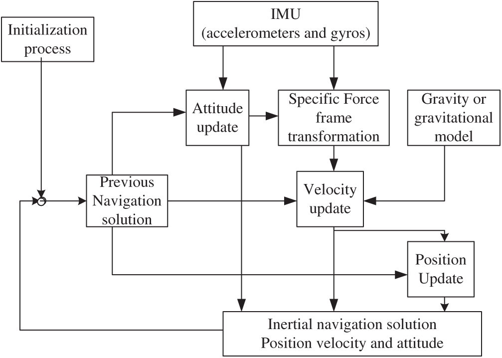
Figure 1: Schematic of strapdown inertial navigation processor
2.3 Wireless Sensor Network Positioning Technology
According to the localization form, the localization technology of wireless sensor network can be divided into two kinds: the localization method based on ranging and the localization method without ranging. The location method based on ranging is to locate the blind nodes by measuring the distance or angle between the blind nodes and the anchor nodes, and the location method without locating the distance directly calculates the location of the blind nodes according to the connectivity of the network [18,19].
RSSI based positioning can be divided into two steps. The first step is ranging, that is, to measure the distance between mobile nodes and anchor nodes. The second step is to locate the mobile nodes based on the algorithm of three edges, maximum likelihood and weighted centroid localization according to the distance from mobile nodes to anchor nodes. The measurement accuracy of the first step distance directly affects the location of the final node, so the distance measurement between the mobile node and the anchor node is very important. We cannot directly measure the distance between the mobile nodes and the anchor nodes, but we can calculate the distance through the received signal strength indicator [20–22]. According to the loss of the wireless signal in the propagation process, we can establish a wireless signal propagation path loss model.
2.4 GNSS/SINS/WSN Integrated Navigation
GNSS and SINS usually have two ways: Loose combination and tight combination [23,24]. Loose combination is to fuse the longitude and latitude output and velocity information of GNSS with SINS data, and tight combination is to combine the pseudo range information of GNSS observation with SINS. Tight combination mode requires higher GNSS receiver, and loose combination mode is easy to be realized in hardware design and software programming. The key of GNSS/SINS integrated navigation system is fusion algorithm. Kalman filter algorithm is the most suitable information fusion algorithm for GNSS/SINS integrated navigation.
Wireless sensor networks locate the coordinates of the mobile nodes. The WSN/SINS integrated navigation algorithm is similar to the GNSS/SINS integrated navigation algorithm. The position error, accelerometer and gyro zero offset are taken as the state variables. The coordinates of the mobile nodes obtained by WSN positioning and the coordinates calculated by SINS are transformed through coordinate transformation. The difference between the two values is taken as the observation, and the final fusion coordinates are obtained by Kalman filter.
According to the filter design, the commonly used multi-sensor fusion algorithms are divided into centralized Kalman filter and Federated Kalman filter. Theoretically, the centralized Kalman filter can get a more accurate estimation of the system than the Federated Kalman filter. However, the centralized Kalman filtering uses a system to process the measured data of all the different sensors. In the multi-sensor fusion integrated navigation, when the sensor type increases, the centralized card will be used. The computational complexity of the Kalman filter increases exponentially, which requires high processor and communication rate. On the other hand, when a sensor fails or produces a large error, the error will spread to the entire filtering system, which may lead to the paralysis of the whole system.
The split Kalman filter uses a global filter and a number of local filters. The local filters are independent of each other and only carry out the filtering task of the type of sensor data. The local filter will be sent to the global filter through the locally filtered data, and the local filter sent by the global filter to the local filter. The optimal estimator is filtered globally to obtain the global optimal estimator and the global co-variance, and the global optimal is fed back to the local filter. Because each local filter works independently, the contaminated data will not seriously affect the operation of the whole system when a sensor fails, which greatly increases the fault tolerance of the system.
3 Proposed GNSS/SINS/WSN Combined Positioning System
3.1 System Demand Analysis and General Block Diagram
The integrated positioning system designed in this paper is mainly composed of GNSS, SINS, WSN positioning module and ARM processor module. The WSN system collects soil and crop information for the field. As this article focuses on designing a positioning and navigation system, in order to simplify the development of the system, the localization function is designed and implemented only when designing WSN. As a function of crop information collection, it can be added in subsequent work.
In this scheme, the device selection and software design should meet three aspects:
(1) Positioning accuracy
The positioning system is a vehicle mounted integrated positioning system, which provides positioning and navigation parameters for agricultural machinery. Taking into account the positioning accuracy of GNSS, SINS and WSN units, the final combination positioning system should reach the positioning accuracy of meter level.
(2) System reliability
Since the system is integrated by a variety of sensors, it is necessary to ensure the reliability of the system. When a sensor fails, the system should continue to work, and the transmission and anti-jamming capability of the system is strong.
(3) Real time
The combined positioning system designed in this paper is to work in a dynamic environment, and the system is in motion state. Therefore, the system must be real-time and complete the positioning and updating of the system in a short time.
The system is made up as shown in Fig. 2.
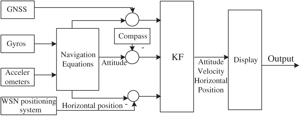
Figure 2: Block diagram of system architecture
3.2 GNSS Data Acquisition and Extraction
The GNSS module selected in this paper is the official NEO-6M module of UBLOX. It is compact but has excellent performance. The module amplifies the amplifier circuit, facilitates the rapid search of the passive ceramic antenna. At the same time, it has the SMA interface to connect the active antenna. The module can set the chip parameters through the serial port and save it in EEPROM, which ensures that the next reset setting is still valid.
The GNSS module acquiescence is NMEA protocol, which is the standard format developed by National Marine Electronics Association for marine electronic equipment. ASCII code is used to transfer GNSS location information, called frame. The data of each frame is separated by commas, and the type of data is determined by the position of commas.
When receiving GNSS data, it first determines the received frame command, and then parses the data after frame command, latitude and longitude, speed and Universal Time Coordinated (UTC) time information. In order to improve processor speed, the system only analyzes frames. First, a structure is defined to store the parsed data, and then the frame head is judged one by one. The required information is obtained based on the comma offset, and the information is stored in the receive buffer and the pointer is moved back to begin to parse the next data.
3.3 Design of Wireless Sensor Network
The development platform selects Embedded workbench, which is able to program coordinator nodes, router nodes and terminal nodes respectively. It has the advantages of complete, stable and convenient use, and supports a variety of ARM processor structures.
In wireless sensor networks, the role of the coordinator is mainly to establish and manage the network, and communicate with the background control center. In order to achieve normal communication between nodes, endpoints and clusters need to be defined. The endpoints are defined in a structural way. In this scheme, the coordinator node is responsible for the establishment and maintenance of the network, the query and configuration functions of the reference node and the mobile node.
The main functions of the reference node are RSSI filtering and distance calculation. The function of collecting other information is not in this design. After sending the location request packet to the reference node, the mobile node extracts the RSSI value from the reference node and uses the Gauss filtering method to process the Gauss filter, then calculates the measurement distance, then sends its own coordinates and measurement distance to the mobile node.
The mobile node is installed on the vehicle positioning system. The main function is to collect the coordinates from the reference node and the distance from the reference node to the mobile node to locate itself. At the same time, the location result is sent to the STM32 microprocessor. After STM32 completes the location data fusion, the fusion result is returned to the mobile node through the serial port. At this point, the mobile node sends the result to the coordinator node.
3.4 Monitoring Center Upper Computer Design
Coordinator nodes in wireless sensor networks communicate with the monitoring center to report the real-time location of agricultural machinery to the monitoring center. The monitoring software is developed based on C++ in VC software. This paper only develops the position receiving function of the monitoring host computer, and other functions are to be followed up. It mainly includes the setting area of serial port, communication status monitoring area, control command area and receiving data display area.
In the serial port setup area, the host program automatically detects the PC available serial port, the default display COM1 port; the baud rate setting box has 14 common baud rate values for use, the lowest 600, the highest 921600; the data bit setup box has 5, 6, 7, 8 four options, the default is 8 bit data bits; parity bit settings. The box has five options: None, Odd, Even, Mark, Space, and the default is None without a check bit; the stop bit has two options, one and two, and the default is 1.
The communication status monitoring area automatically monitors the serial port state and the number of bytes sent and received by the host computer, and at any time, the number of sending and receiving bytes can be cleared at any time.
The control command window can configure the coordinator parameters associated with it, mainly including A and N values.
The receiving data display area is displayed on the host computer according to the location information of the combined positioning system sent by the coordinator node, plus a label and a time stamp.
In order to test and analyze the performance of the integrated navigation system designed in this paper, each subsystem and the global fusion data are sent to the PC terminal through serial port 1 when data are collected, and it is received and saved by serial assistant. Due to the limited conditions, the school soccer field similar to the farmland environment is chosen as the testing site. The system is a GNSS/SINS/WSN integrated positioning system. Therefore, a wireless sensor network is built before the test. The coordinator node and 6 anchor nodes are built. Firstly, the system is stationary on the ground, and the data received by the serial port are analyzed to compare the positioning results of the system. When receiving, the system needs to start the wireless sensor network first and wait for one minute to start the integrated positioning system. After the start of the integrated positioning system, it also needs to wait for 2 minutes to complete the initial alignment of the SINS receiver module and the measurement noise distribution statistics of the system.
From Fig. 3, it can be seen that the GNSS/SINS/WSN positioning system is more stable than the SINS positioning system, the results are more in line with the actual positioning position.
Figure 3: Static test contrast
Then the hand-held integrated positioning system keeps the uniform linear motion as far as possible in the wireless sensor network, records the data and draws the graph.
In motion, the navigation system sends the collected data to the computer terminal in real time through the serial port, and runs the host computer on another computer to receive the location information sent by the coordinator node. The data received by the host computer is shown as shown in the following figure.
After that, the saved data is extracted and drawn by computer on MATLAB, and the positioning coordinates of each system are all converted to the earth coordinate system.
The real trajectory in the diagram is formed by connecting the boundary points and can be seen as a straight line in the course of walking. The coordinates of each discrete point are subtracted from the coordinates of the corresponding points in the real trajectory to get the error values, and the positioning errors of each system are obtained by calculation and statistics.
Figure 4: Positioning error
The average positioning error of GNSS/SINS is 2.223 meters, that of WSN/SINS is 3.34 meters, and that of GNSS/ISINS/WSN is 1.983 meters in Fig. 4. The experimental results show that the positioning accuracy of the GNSS/SINS/WSN system is higher than that of the GNSS/SINS and WSN/SINS integrated positioning system. And from the trajectory, we can see that the trajectory of the GNSS/SINS/WSN positioning system designed in this paper is smoother and can better track the position of the carrier.
At present, RTK-GNSS is adopted in the automatic agricultural navigation system. This scheme has the advantage of high accuracy and can satisfy any type of operation, but its price of more than ten million has greatly limited its application and popularization. Other positioning and navigation methods such as machine vision, GNSS or GNSS/SINS integrated navigation have the shortcomings of SINS insufficient positioning accuracy and low system stability. Based on this, this paper takes into account the application of precision agriculture in the field of automatic driving of agricultural machinery. The wireless sensor network built in precision agriculture can not only communicate, but also has the positioning function. It integrates the localization function of wireless sensor network into GNSS/SINS integrated positioning, and improves the fusion through Kalman filtering algorithm. At the same time, the positioning accuracy of the system greatly enhances the stability of the system.
Acknowledgement: The authors would like thank anonymous reviewers who read drafts and made many helpful suggestions.
Funding Statement: This work was supported in part by Natural Science Foundation of Jiangsu Province under Grant BK20160955, a project funded by the Priority Academic Program Development of Jiangsu Higher Education Institutions and Science Research Foundation of Nanjing University of Information Science and Technology under Grant 20110430. Open Foundation of Jiangsu Key Laboratory of Meteorological Observation and Information Processing (KDXS1304), Open Foundation of Jiangsu Key Laboratory of Ocean Dynamic Remote Sensing and Acoustics (KHYS1405).
Conflicts of Interest: The authors declare that they have no conflicts of interest to report regarding the present study.
1. F. Gulmammadov. (2009). “Analysis, modeling and compensation of bias drift in MEMS inertial sensor,” in IEEE Int. Conf. Recent Advance in Space Technologies, Istanbul, Turkey, pp. 591–596. [Google Scholar]
2. H. Hu and X. Huang. (2010). “SINS/CNS/GPS integrated navigation algorithm based on UKF,” Journal of Systems Engineering and Electronics, vol. 21, no. 1, pp. 102–109. [Google Scholar]
3. C. Jiang, S. Chen, Y. Chen and Y. Bo. (2018). “Research on a chip scale atomic clock driven GNSS/SINS deeply coupled navigation system for augmented performance,” IET Radar Sonar & Navigation, vol. 13, no. 2, pp. 326–331. [Google Scholar]
4. J. Li, J. Fang and M. Du. (2012). “Error analysis and gyro-bias calibration of analytic coarse alignment for airborne POS,” IEEE Transactions on Instrumentation and Measurement, vol. 61, no. 11, pp. 3058–3064. [Google Scholar]
5. K. Li, W. He, Z. Zhang and Q. Zhou. (2017). “Node localization for wireless networks in smart distribution automation,” International Journal of Sensor Networks, vol. 23, no. 1, pp. 53–60. [Google Scholar]
6. Y. Li and Z. Zhao. (2011). “Research on the method of positioning correction for field navigation vehicles based on Kalman filter,” Agricultural Equipment and Vehicle Engineering, vol. 49, no. 9, pp. 3–9. [Google Scholar]
7. Z. Liu and G. Liu. (2010). “Tractor automatic navigation system based on adaptive fuzzy control,” Journal of Agricultural Machinery, vol. 41, no. 11, pp. 148–152. [Google Scholar]
8. D. Narjes and G. Asghar. (2017). “An asynchronous adaptive direct Kalman filter algorithm to improve underwater navigation system performance,” IEEE Sensors Journal, vol. 17, no. 4, pp. 1061–1068. [Google Scholar]
9. X. Ning, J. Zhang, M. Gui and J. Fang. (2018). “A fast calibration method of the star sensor installation error based on observability analysis for the tightly coupled SINS/CNS-integrated navigation system,” IEEE Sensors Journal, vol. 18, no. 16, pp. 6794–6803. [Google Scholar]
10. F. Qu, T. Li, A. Xie and Q. Kong. (2013). “Application of wireless sensor networks in military,” Electronic Design Engineering, vol. 21, no. 15, pp. 34–36. [Google Scholar]
11. Q. Wang, C. S. Yang, S. E. Wu and Y. X. Wang. (2019). “Lever arm compensation of autonomous underwater vehicle for fast transfer alignment,” Computers, Materials & Continua, vol. 59, no. 1, pp. 105–118. [Google Scholar]
12. Q. Wang, C. S. Yang, S. E. Wu and Y. Wang. (2020). “Application of gravity passive aided strapdown inertial navigation in underwater vehicles,” International Journal of Sensor Networks, vol. 32, no. 4, pp. 209–217. [Google Scholar]
13. S. Salan, M. Eduardo and F. Hugh. (1999). “A high integrity IMU/GPS Navigation loop for autonomous land vehicle applications,” IEEE Transactions on Robotics and Automation, vol. 15, no. 3, pp. 572–578. [Google Scholar]
14. C. Shu. (2016). “Research and verification of road condition optimization for floating vehicle based on WSN and GNSS fusion positioning,” Traffic Standardization, vol. 2, no. 4, pp. 62–71. [Google Scholar]
15. J. Wang, Y. Gao, W. Liu, A. K. Sangaiah and H. J. Kim. (2019). “An intelligent data gathering schema with data fusion supported for mobile sink in wireless sensor networks,” International Journal of Distributed Sensor Networks, vol. 15, no. 3, pp. 155–174. [Google Scholar]
16. X. Wei, X. Wang, X. Bai, S. Bai and J. Liu. (2017). “Autonomous underwater vehicles localisation in mobile underwater networks,” International Journal of Sensor Networks, vol. 23, no. 1, pp. 61–71.
17. H. Wu. (2010). “Research on fusion localization algorithm of GNSS and wireless sensor network,” Computer Simulation, vol. 26, no. 11, pp. 145–148. [Google Scholar]
18. X. Xu, Y. Dong, J. Tong and W. Dai. (2017). “Improved fifth-degree spherical simplex sadial cubature Kalman filter in SINS/DVL integrated navigation,” Journal of Chinese Inertial Technology, vol. 25, no. 3, pp. 343–348. [Google Scholar]
19. J. Yan, X. Xu, T. Zhang, Y. Liu and W. Liang. (2013). “Design of marine-based miniature tightly integrated SINS/GNSS navigation system,” Journal of Chinese Inertial Technology, vol. 21, no. 6, pp. 775–780. [Google Scholar]
20. W. Ye, J. Li, J. Fang and X. Yuan. (2018). “EGP-CDKF for performance improvement of the SINS/GNSS integrated system,” IEEE Transactions on Industrial Electronics, vol. 65, no. 4, pp. 3601–3609. [Google Scholar]
21. T. Zhang, L. Chen, H. Shi and H. Hu. (2015). “Underwater positioning system based on SINS/DVL and LBL interactive auxiliary for AUV,” Journal of Chinese Inertial Technology, vol. 23, no. 6, pp. 769–774.
22. T. Zhang, X. Xu, X. Liu, S. Tian and Y. Liu. (2012). “Time synchronization on SINS/GPS integrated navigation system under different dynamic conditions,” Journal of Chinese Inertial Technology, vol. 20, no. 3, pp. 320–325. [Google Scholar]
23. J. Zhou, X. Wang and R. Zhang. (2012). “Location method of GNSS and DR integrated navigation system for agricultural locomotives,” Journal of Agricultural Machinery, vol. 43, no. 10, pp. 262–265. [Google Scholar]
24. J. Zhou, M. Zhang and M. Wang. (2017). “Route tracking of agricultural vehicles based on fuzzy control,” Journal of Agricultural Machinery, vol. 40, no. 4, pp. 151–156. [Google Scholar]
 | This work is licensed under a Creative Commons Attribution 4.0 International License, which permits unrestricted use, distribution, and reproduction in any medium, provided the original work is properly cited. |