DOI:10.32604/iasc.2021.01002
| Intelligent Automation & Soft Computing DOI:10.32604/iasc.2021.01002 | |
| Article |
AUV Global Security Path Planning Based on a Potential Field Bio-Inspired Neural Network in Underwater Environment
1School of Physics and Electronic Electrical Engineering, Huaiyin Normal University, Huai’an, 223300, China
2School of Automation, Southeast University, Nanjing, 210096, China
3School of Computer Science and Technology, Huaiyin Normal University, Huai’an, 223300, China
4State Grid Jiangsu Electric Power Co., Ltd., Huai’an Power Supply Branch, Huai’an, 223001, China
*Corresponding Author: Xiang Cao. Email: cxeffort@126.com
Received: 02 October 2020; Accepted: 06 November 2020
Abstract: As one of the classical problems in autonomous underwater vehicle (AUV) research, path planning has obtained a lot of research results. Many studies have focused on planning an optimal path for AUVs. These optimal paths are sometimes too close to obstacles. In the real environment, it is difficult for AUVs to avoid obstacles according to such an optimal path. To solve the safety problem of AUV path planning in a dynamic uncertain environment, an algorithm combining a bio-inspired neural network and potential field is proposed. Based on the environmental information, the bio-inspired neural network plans the optimal path for the AUV. The potential field function adjusts the path planned by the bio-inspired neural network so that the actual AUV can avoid obstacles. The proposed approach for AUV path planning with safety consideration is capable of planning a real-time “comfortable” trajectory by overcoming either “too close” or “too far” shortcomings. Simulation and experimental results show that the proposed algorithm considers both AUV security and path rationality. The planned path can meet the need for collision-free navigation of AUVs in a dynamic, uncertain environment.
Keywords: Autonomous underwater vehicle; bio-inspired neural network; path planning; potential field
As one of the key technologies of underwater target searches and map construction, autonomous underwater vehicle (AUV) path planning has been widely studied [1–4]. Path planning is a non-collision path automatically planned by an AUV from a starting position to a goal according to the specific functions of task requirements and constraints [5–8]. The path-planning algorithm the path to be as short as possible under the premise of AUV security.
From the perspective of the AUV perceiving the environment, path-planning methods can be divided into three categories: Those based on environment models, case-based learning planning methods, and behavior-based path planning methods. From the perspective of whether the planning environment changes with time, it can also be divided into static and dynamic path planning methods. Based on the models and methods used in current path planning, this paper summarizes and generalizes the existing path planning techniques of mobile robots into the following four categories: template-matching path planning technique, artificial potential field path planning technique, map building path planning technology, and Artificial intelligence path planning technology.
The template-matching method compares the current state of the AUV with experience, finds the closest state, and modifies the path under this state, and then a new path can be obtained [9,10]. First, a template library is established by using the known information used in path planning. The template in the library contains various environmental information and corresponding path information. These templates can be obtained with a specific index, and then the AUV’s current planning task and environment information are matched with the template in the template library to find an optimal matching template, which is then modified as the final result of the path planning.
Template-matching technology has a good application effect when the environment is determined. For example, Liu et al. [11] proposed a template matching the path planning method for cleaning robots [12]. To improve the adaptability of template matching path planning technology to environmental changes, some scholars proposed a method combining template matching with artificial neural network learning, such as Ram et al. [13], who combined online case-based matching and enhanced learning to improve the adaptive performance of a robot in the template matching planning method, enabling the robot to partially adapt to environmental changes. Arleo et al. [14] proposed a path planning method combining the environment template with neural network learning.
Artificial potential field (APF) path planning is one of the classical methods for robot path planning. The basic idea considers robot movement in the environment as a virtual force field in the movement; the obstacles to the robot repulsion, target gravitational pull on the robot, and attraction and repulsion force drive the robot to the goal; and the resultant force is the power of acceleration of the robot, which can be used to control the movement direction of the robot [15–18]. Rasekhipour et al. [19] proposed the APF algorithm for path planning of an autonomous surface vehicle (ASV) in a real-time marine environment. In Berger et al. [20], the discrete rescue path planning problem for a single agent navigating in an uncertain adversarial environment was solved. Experimental results show the value of the proposed approach in computing near-optimal solutions reasonably quickly for various problem instances. In general, the traditional optimizing methods easily tend to fall into the local minimum. Therefore, the efficiency of the traditional optimization method is low.
The path planning technology of mapping is to divide the area around a robot into different grid spaces (such as free space and restricted space) according to the obstacle information obtained by the robot's sensors, calculate the possession of obstacles in the grid space, and then determine the optimal path according to certain rules. Wang et al. [21] studied path planning for first responders in the presence of uncertain moving obstacles by a modified A* algorithm that can deal with the uncertainty and generate fast and safe routes passing through the obstacles. Uttendorf et al. [22] integrated the A* algorithm and the fastest descent method, which was used for grid-based path planning. The A* algorithm is a node-searching strategy; that is, it uses the heuristic function to estimate the cost of the path from the start to the goal in the grid maps. The branching factor of the A* algorithm describes the moving directions, which will be selected according to the path length in different grid maps. The steepest descent method adopts a heuristic-based gradient method with grid maps to search for the shortest path.
Bortoff [23] proposed a suboptimal rough-cut path through radar sites by constructing and searching a graph based on Voronoi polygons. Wang et al. [24] used a threat probability map instead of a Voronoi polygon to generate the initial solution of a multi-vehicle path planning problem. To derive efficient solutions for motion planning in the practical world, the rapidly-exploring random tree (RRT) algorithm has been extensively explored. The RRT algorithm presents a solution regardless of whether the specific geometry of the obstacles is known beforehand [25,26]. Various algorithms enhancing the original RRT algorithm have been proposed. For example, Zaid et al. [27] introduced a new variant called intelligent bidirectional-RRT* (IB-RRT*), which is an improved variant of the optimal RRT* and bidirectional version of RRT* (B-RRT*) algorithms and is specially designed for a complex cluttered environment. IB-RRT* utilizes the bidirectional trees approach and introduces an intelligent sample insertion heuristic for fast convergence to the optimal path solution using uniform sampling heuristics. This algorithm guarantees eventual convergence to an optimal path solution, unlike the original RRT algorithm.
Artificial intelligence (AI) is a new technical science implemented to research and develop theories, methods, technologies, and application systems used to simulate, extend, and extend human intelligence. Modern AI technology has been widely used to solve the problem of path planning for robots.
The genetic algorithm (GA) is one of the most commonly used methods in path planning. Romero et al. [28] used the GA to solve the multi-constraints three-dimensional (3D) unmanned aerial vehicle (UAV) path planning problem. Qu et al. [29] presented the co-evolutionary strategy based GA using the binary codes through matrix for mobile robot navigation in static and dynamic environments. This approach transforms the environment from chaos to an array.
Particle swarm optimization (PSO) is a common path planning algorithm. It is important ensuring the radiation safety of workers in nuclear facilities. Wang et al. [30] proposed an improved PSO algorithm to solve path-planning problems. Specifically, the PSO algorithm is associated with a chaos optimization algorithm, and new mathematical dose calculation models for the path-planning problem are built. Wang et al. [31] compared the parallel GA with the parallel PSO algorithm in a real-time 3-D path-planning problem. Lee [32] developed an anytime algorithm using PSO to solve the intelligent robot path-planning problem.
Another commonly used path-planning algorithm is the bio-inspired neural network in the field. Cao et al. [33] made an in-depth study of AUV path planning. They devised a combination of a velocity synthesis algorithm with a biologically inspired neurodynamics model for an underwater environment affected by ocean currents. It is expected to provide shorter paths than other algorithms in an underwater environment with ocean currents and obstacles. Yang et al. [34] introduced a bio-inspired neural network algorithm to lead the robot to search for unknown environments. This method is capable of planning more reasonable and shorter collision-free complete coverage searching paths in an unknown environment. Although the bio-inspired neural network algorithm has obtained some good results for a mobile robot, its workspace is different from the practical underwater environment.
Although most AI methods have a powerful ability of global optimization, the efficiencies of the different methods are uneven for the same problem [35]. For example, the bio-inspired neural network approach of AUVs is an original approach that can be applied to generate a real-time collision-free trajectory under a dynamic uncertain environment. The planned path may not prevent an AUV from approaching obstacles “too close”. In this case, the AUV may collide with an obstacle in the actual underwater environment. Furthermore, the generated path may not be in accord with the restriction that the path length should be short to the greatest extent when the approach is applied in point-to-point path planning [36].
In this study, a potential field bio-inspired neural network (PBNN) in conjunction with the developed virtual obstacle algorithm (VOA) and safety aware navigation algorithm is utilized for an AUV [37]. The PBNN is applied to AUV path planning. In this biologically inspired neural network model, the planned AUV motion in a static environment is globally optimal although there is no explicit optimization of any global cost functions. The potential field is utilized to adjust the planning path of the bio-inspired neural network, and achieve AUV path planning. The real-time AUV path is planned through the dynamic activity landscape of the neural network without any prior knowledge of the dynamic environment, and thus it is computationally efficient. The proposed model for AUV path planning with safety consideration is capable of planning a real-time “comfortable” trajectory by overcoming either “too close” or “too far” shortcomings. Simulation studies validated that the proposed approach was capable of performing safe and efficient navigation of an AUV. In addition, the proposed approach has better adaptability compared with other algorithms.
The rest of the paper is organized as follows. In Section 2, the problem statement is given. Section 3 introduces the mechanism of the path planning algorithm. The simulation experiments for various situations are given in Section 4, and the conclusion is given in Section 5.
In this study, the security of a real-time AUV path is designed in an underwater environment. The safety aware navigation is taken into consideration by virtual enlarged obstacles in the environment. The obstacles are enlarged by the previously modeled obstacle enlargement algorithm illustrated. The AUV is driven by the proposed PBNN model, and the VOA is navigated along a smooth trajectory, which constantly retains a safer and more “comfortable” distance from the obstacle. In the underwater environment, there are the AUV, goal (static or dynamic), and several obstacles of different sizes and shapes. The turning radius of the AUV is ignorable compared with the dimension of the underwater workspace; thus, the AUV is assumed to be able to move omnidirectionally. The AUV is supposed to be informed about the underwater environment and the boundaries of their workspace. The AUV and dynamic goals are only allowed to move within the workspace. Among these, the dynamic goal moves at random, while the AUV moves according to the proposed algorithm. When the AUV moves from the starting position to the goal position, the path-planning task is ended.
3 Path Planning Strategy Equations and Mathematical Expressions
Owing to the complicated underwater environment, AUV path planning may encounter obstacles. When encountering obstacles, the AUV estimates distance and take measures to avoid obstacles. PBNN is introduced in this study to achieve path planning and obstacle avoidance.
3.1 Bio-inspired Neural Network
The bio-inspired neural network was first proposed by Grossberg [38], derived from circuitry in biofilms by Hodgkin et al. [39]. It is considered to be a real-time adaptive behavior of a monomer. In this paper, the path of an AUV is planned by the bio-inspired neural network. The main reason for using this bio-inspired neural network is that it is not only a feasible solution but also an efficient one. The proposed neural network is topologically organized, in which the dynamics of each neuron is characterized by a shunting or additive equation. The real-time optimal trajectory is generated through the dynamic activity landscape of the neural network without explicitly searching over the free space nor the collision paths, without any prior knowledge of the dynamic environment, and without any learning procedures. First, a bio-inspired neural network is built according to a 3D grid map of an underwater environment (as shown in Fig. 1).
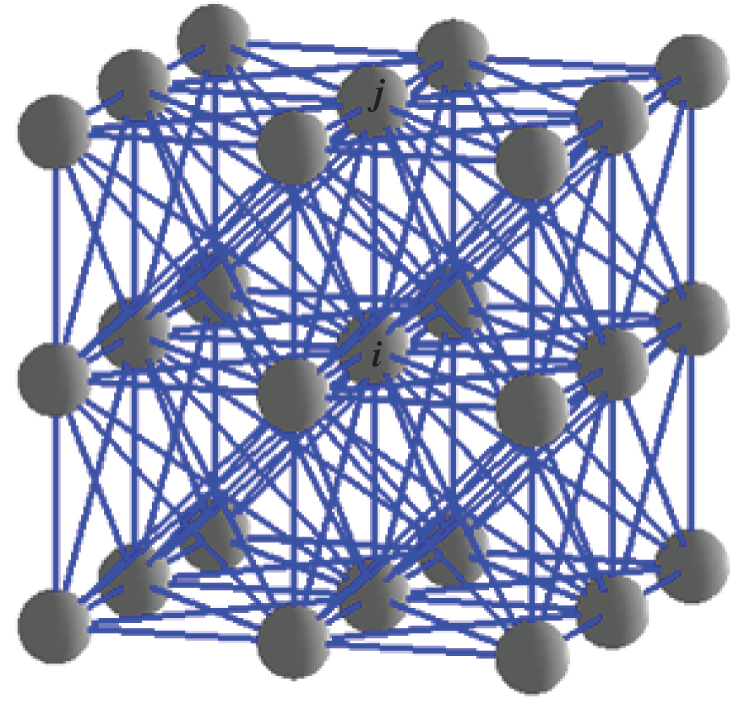
Figure 1: 3D bio-inspired neural network structure
In this model, a neuron represents a grid cell. Information of the grid cell is described by the neural activities. Each neuron is connected with adjacent ones to form a network for their transmission of activity. As shown in Fig. 1, each neuron has contact with the surrounding 26 neurons and stimulate or inhibit each other. According to bio-inspired neural network structure, the dynamic active output value differential equation of the i-th neuron is [40,41]:

where k denotes the number of neurons surrounding the i-th neuron.  denotes the external input of the i-th neuron and is defined as
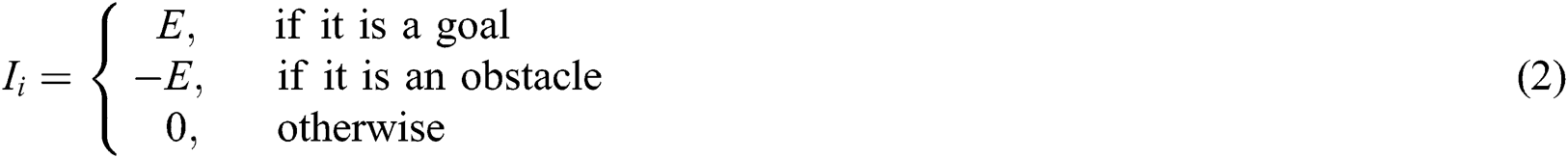
where E is a positive constant that is far greater than B. This guarantees, in the entire neural network, the active values of the goal neurons mean the peak, and the obstacle point means the valley. 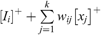 represents the excitation signal, and
  represents the inhibitory signal, and
  is the Euclidean distance between neuron i and its neighbor j in the 3D space:

where (xi, yi, zi) is the coordinate of the i-th neuron in the 3D coordinate system, and (xj, yj, zj) coordinate of the j-th neuron in the 3D coordinate system.
In Eq. (4), wij is the connection weights between neuron i and its neighbor j, which can be defined as [42]:

where  is a positive constant, and generally,
 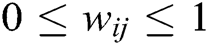 . As the connections between neurons are not directional, the connection weight coefficients are symmetrical; that is
  .
.
Owing to Eq. (1), the activity value of the neuron in the goal is positive, while those of the neurons in the obstacles are negative. This means one part of the excitation signals comes from external input while the other part comes from internal incremental gains of interconnecting neurons. If  , which means that there is no external input for neuron i, and all its excitation signals are transmitted through the neuronal network. In contrast, all the inhibitory input for signals i are external. Therefore, the excitation signals transmit between neurons, and the value of the positive activity of neurons in a neural network has a global effect, while the inhibitory signals do not transmit and the negative activity of neurons has only a local effect.
Obviously, in the bio-inspired neural network path planning approach, there are two shortages: (i) The planned path may not prevent an AUV from approaching obstacles “too close”, and (ii) The generated path may not be in accord with the restriction that the length of the path should be short to the greatest extent when the approach is applied in point-to-point path planning. In this case, the AUV may collide with an obstacle in the actual underwater environment. The underwater environment with each AUV’s moving ability is supposed in an ideal condition.
To avoid obstacles, the potential field is applied to regulate the planning path of the bio-inspired neural network, and an integrated PBNN method is proposed in this paper. To better understand the PBNN algorithm, a potential field is introduced for AUV path planning by overcoming the “too close” shortcoming and security path under obstacles condition.
The potential-field algorithm is a commonly used method for AUV path planning in an underwater environment [43]. In this subsection, the potential-field function-value calculation is based on the attractive and repulsive potential functions, which are mainly related to the target relative distance and velocity, and the obstacle’s relative distance. After the calculation of the attractive and repulsive potential, the potentials field function can be obtained by

where U is the potential field function, p is the AUV’s position; Uatt(p, v) denotes the attractive potential function generated by the goal, Urep (p, v) is the repulsive potential function generated by the obstacle, and v is the AUV velocity.
The attractive potential is defined as a function of the relative distance and velocity between the AUV and the goal. The attractive potential-field functions are expressed as follows [44]:

where ptar denotes the positions of the goal; v and vtar denote the velocities of the AUV and goal, respectively;  is the Euclidean distance between the AUV and goal;
  is the magnitude of the relative velocity between the goal and AUV; αp and αv are scalar positive parameters; and m and n are positive constants.
An intuitive way of preventing an AUV from approaching obstacles “too close” is to take into account the relative positions and velocities between the AUV and obstacles when constructing the repulsive potential function. In this subsection, a repulsive potential function is presented that makes use of the position information of the obstacles. The repulsive potential only stays locally. The influence range of the repulsive potential is the obstacle enlargement area. Considering that the goal may appear in the obstacle enlargement area, the repulsive potential increases as the distance from the obstacle decreases. The repulsive potential at the boundary of the obstacle enlargement is small. Therefore, the AUV can enter the obstacle enlargement area when needed. However, the repulsive potential at the boundary of the obstacle is very large, which prevents the AUV from colliding with the obstacle. Accordingly, the repulsive potential can be defined as [45]:
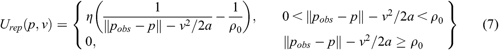
where ρ0 is a positive constant describing the influence range of the repulsive potential, and  is the Euclidean distance between the AUV and the obstacle. Deceleration of magnitude a is applied to the AUV to reduce its velocity, and η is a positive constant.
In the AUV path-planning task, the motions of the AUV are guided by the dynamic activity landscape of the neural network and potential field function. The activity of each neuron is determined by a shunting equation, i.e., Eq. (1). The potential field function is calculated by a shunting equation derived from Eq. (5). The AUV’s movement is determined by the landscape of the dynamic activity of the topologically organized neural network and potential field. The strategy of AUV path selection can be expressed as follows:

where M represents the numbers of the i-th neuron’s neighbors, β and λ are positive constants, Pnext represents the AUV’s location of next moment in the map, and  is the largest value of the sum of the active value and the potential field of the i-th neuron’s neighbors. When an AUV makes a path selection, it compares
  of the neuron of its current location with its neighbors and chooses the one with the highest value as the next step. Repeating this performance, the AUV keeps moving towards the goal.
3.4 Safety-Aware Navigation Algorithm
In this subsection, the obstacle enlargement algorithm associated with the proposed PBNN is addressed. The algorithm contains two portions: The obstacle enlargement and the navigation portions.
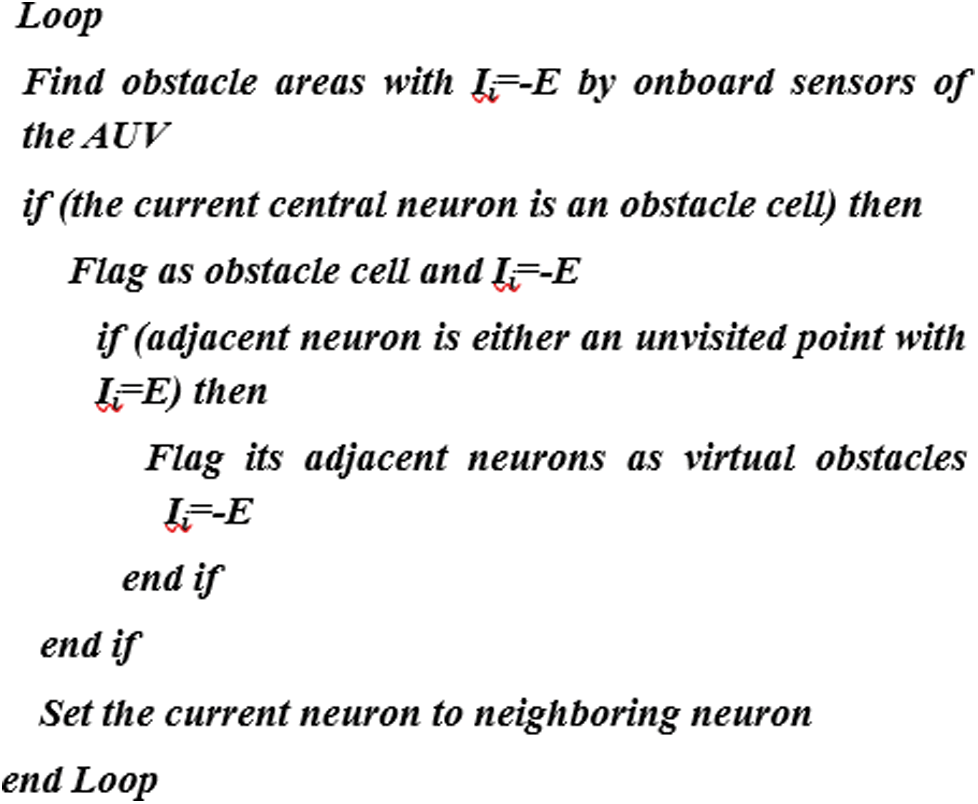
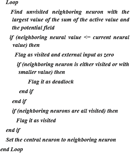
Obstacle enlargement algorithm portion: This algorithm mainly relies on the AUV’s onboard range sensors. The obstacles populated in the workspace in the proposed model are assumed to be known. Cell representation is utilized in this paper for environmental information. Once a cell (grid) represented for obstacles is detected by the onboard sensors of the vehicle as a neuron, its neurons are to be marked as Ii = –E in Algorithm 1.
Autonomous navigation algorithm portion: The goal globally attracts the AUV in the entire state space through activity propagation, while the obstacles have only local effects in a small region to avoid collisions. The autonomous navigation algorithm is shown in Algorithm 2. Based on the previously addressed obstacle enlargement algorithm, the AUV applying the Autonomous Navigation algorithm generates a safe distance from obstacles.
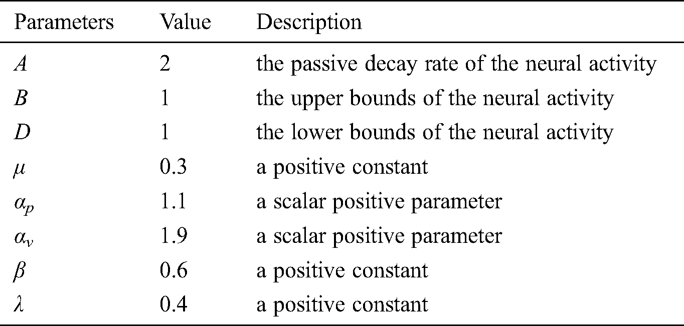
In the simulation, a starting position and goal are randomly positioned in free space for each map, and the experiment is conducted to find a path from the starting to the goal. The 2D and 3D underwater environments are considered in this work to validate the performance of the proposed methodology. To demonstrate the effectiveness of the proposed algorithm for path planning by an AUV in an underwater environment with obstacles, several simulations coded in MATLAB were conducted. In the simulations, the maps are different in terms of the number of obstacles, shapes of obstacles, size of the map, and narrowness of roads. These simulations include various cases, such as both static and dynamic goals. In addition, comparisons between the proposed algorithm and PSO are conducted. The parameters used in all experiments are shown in Tab. 1.
4.1 AUV Path Planning in 2D Underwater Environments
Here, the bio-inspired neural network (BNN) and PBNN algorithms were applied to see how points would surround critical obstacles and how the PBNN would improve paths about path length when an identical initial width was given for all maps. In the simulation, the safe distance between the AUV and obstacle is assumed to be a grid. The results are shown in Fig. 2. Two algorithms can implement AUV path planning. In the BNN algorithm, since the goal will impact the entire area through neural transmission, the activity of each neuron can be derived from the shunting equation (Eq. (1)). When an AUV makes a selection of its path, it compares the activity value of the neuron of its current location with its neighbors and chooses the one with the highest value as the next step. In the proposed algorithm, the goal and obstacles are excitations and inhibitors of the neural network, respectively. Repeating this performance, the AUV keeps moving towards the goal, and AUVs can by-pass obstacles to avoid a collision. To shorten the path, the BNN controls the AUV from approaching obstacles “too close”, so it is easy to collide with obstacles. The result is shown in Fig. 2a. In the PBNN, in addition to the path-planning based BNN, obstacles are amplified according to the repulsive potential function. AUVs by-pass enlarged obstacles. The AUV path is capable of planning a real-time “comfortable” path by overcoming the “too close” shortcoming. The result is shown in Fig. 2b. The simulation results show that the proposed algorithm can plan a safer path for the AUV.
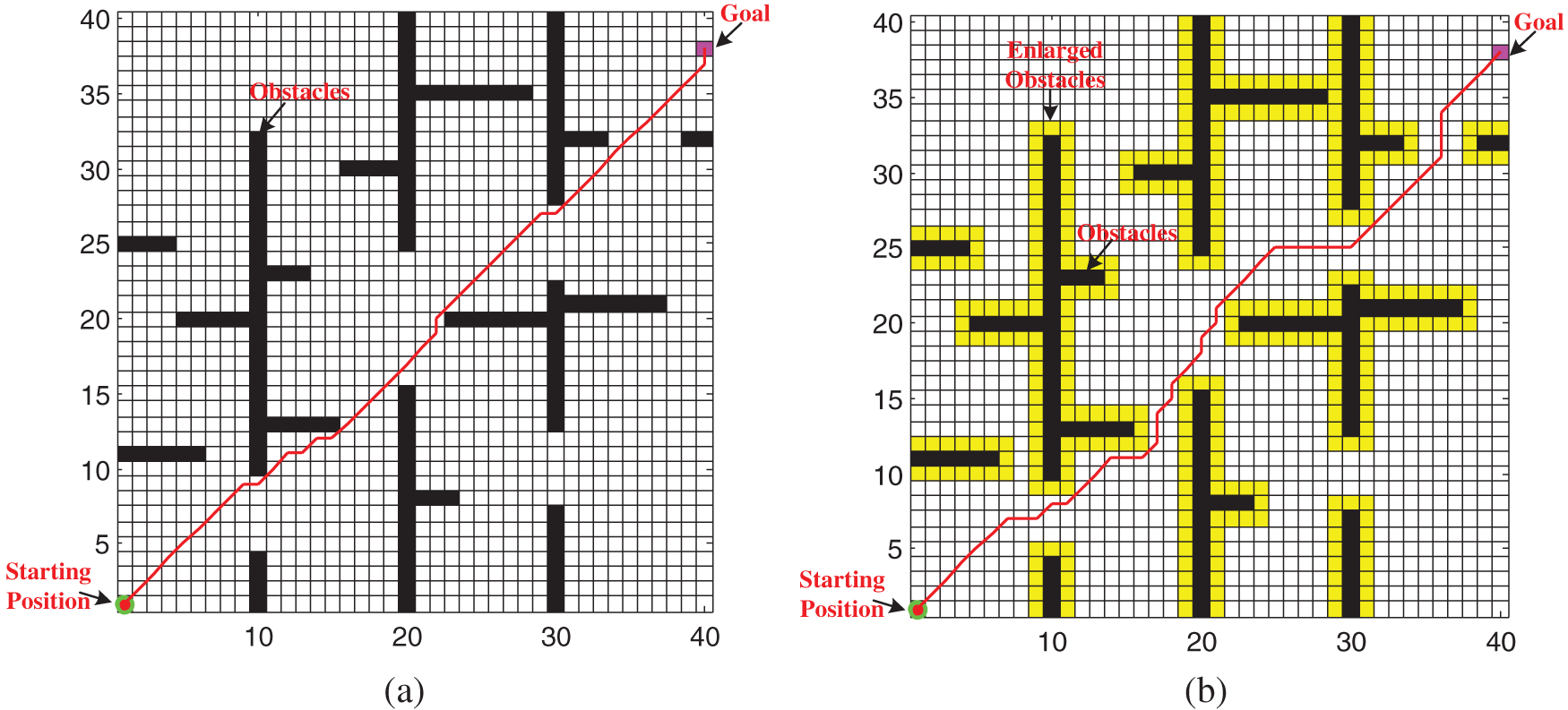
Figure 2: AUV path planning in a 2D underwater environment with static goal (a) BNN, (b) PBNN
Analysis of the reasons for the above results shows that the BNN algorithm achieves the optimal path by selecting the maximum position point of the active value of neurons while ignoring the safe distance between the AUV and obstacles. The proposed algorithm not only considers the optimal path but also introduces the potential field function and obstacle enlargement algorithm to consider the safe distance between the obstacle and AUV. Therefore, the path of algorithm planning is safer and more suitable for practical application than that of BNN algorithm planning.
The goal will move because of the water currents. A second simulation was conducted to test path planning for a dynamic goal, which will undoubtedly cause more difficulties. However, the algorithm proposed in this paper specifically overcomes this difficulty. Owing to the pre-definition, the activity values of the neurons in the goal are positive, and the goal globally attracts AUVs through the dynamic neural activity landscape of the model. According to Eq. (1), activity values of the AUV’s neighbor neurons will change accordingly when the goal’s location changes. Through the change of activity values of neighboring neurons, the real-time information about the ever-changing locations of the mobile goal can be obtained by the AUV. Moreover, the attractive potential function can further attract the AUV. The proposed algorithm can constantly adjust search paths according to changes in the neighboring neural activity value and attractive potential function. The results are shown in Figs. 3c and 3d. Because the generated path may not be in accord with the restriction that the length of the path should be short to the greatest extent when the BNN is applied in point-to-point path planning, as shown in Figs. 3a and 3b, the path of the BNN algorithm is longer than that of the PBNN algorithm.
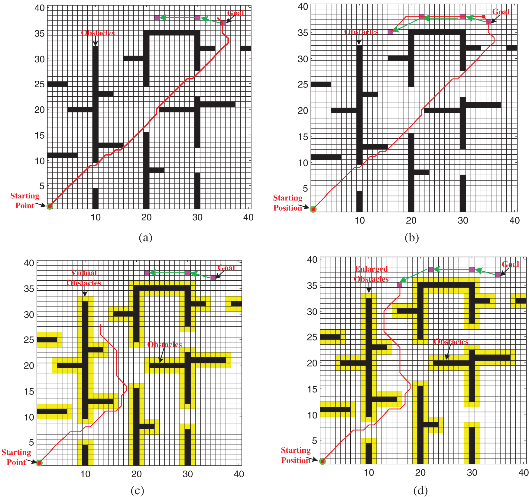
Figure 3: AUV path planning in a 2D underwater environment with dynamic goal (a) Path planning process of BNN, (b) Path planning result of BNN, (c) Path planning process of PBNN, (d) Path planning result of PBNN
To further consider the applicability of the proposed algorithm, AUV path planning of a dynamic goal entering the obstacle enlargement area was simulated. According to the simulation results shown in Fig. 4, the proposed algorithm can complete the path planning of a dynamic goal entering the obstacle enlargement area. This is because the goal’s landscape of dynamic activity and attractive potential field is the largest. Although the dynamic goal enters the obstacle enlargement area,  of the target is still a local maximum by the superposition of the active value and potential field. According to Eq. (8), the AUV can reach the goal.
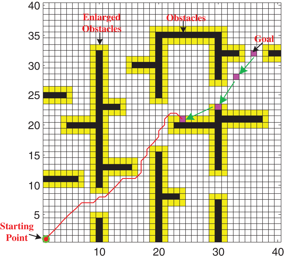
Figure 4: AUV path planning of dynamic goal entering the obstacle enlargement area
4.2 AUV Path Planning in 3D Underwater Environment
The proposed PBNN algorithm can path plan not only the 2D underwater environment but also the 3D underwater environment. To test the performance of the proposed algorithm, the simulations conducted path planning for static and dynamic goals in the 3D underwater environment. These simulations involved one goal, one AUV, and several obstacles in an underwater workspace. The initial locations of the goal were (9, 9, 9). The initial locations of the AUV were (1, 1, 1). According to the path-planning principle mentioned above, the AUV completed the path planning of a 3D underwater environment, as shown in Figs. 5 and 6. Figs. 5a–5d show the path planning of the AUV in the different 3D underwater environments with the static goal. Figs. 6a and 6b show the path planning of the AUV in the different 3D underwater environments with the dynamic goal. According to the path of the AUV in Figs. 5 and 6, the proposed algorithm can plan the short path under the premise of the AUV navigating safely. This shows that the proposed PBNN algorithm overcomes the disadvantages of the BNN algorithm.
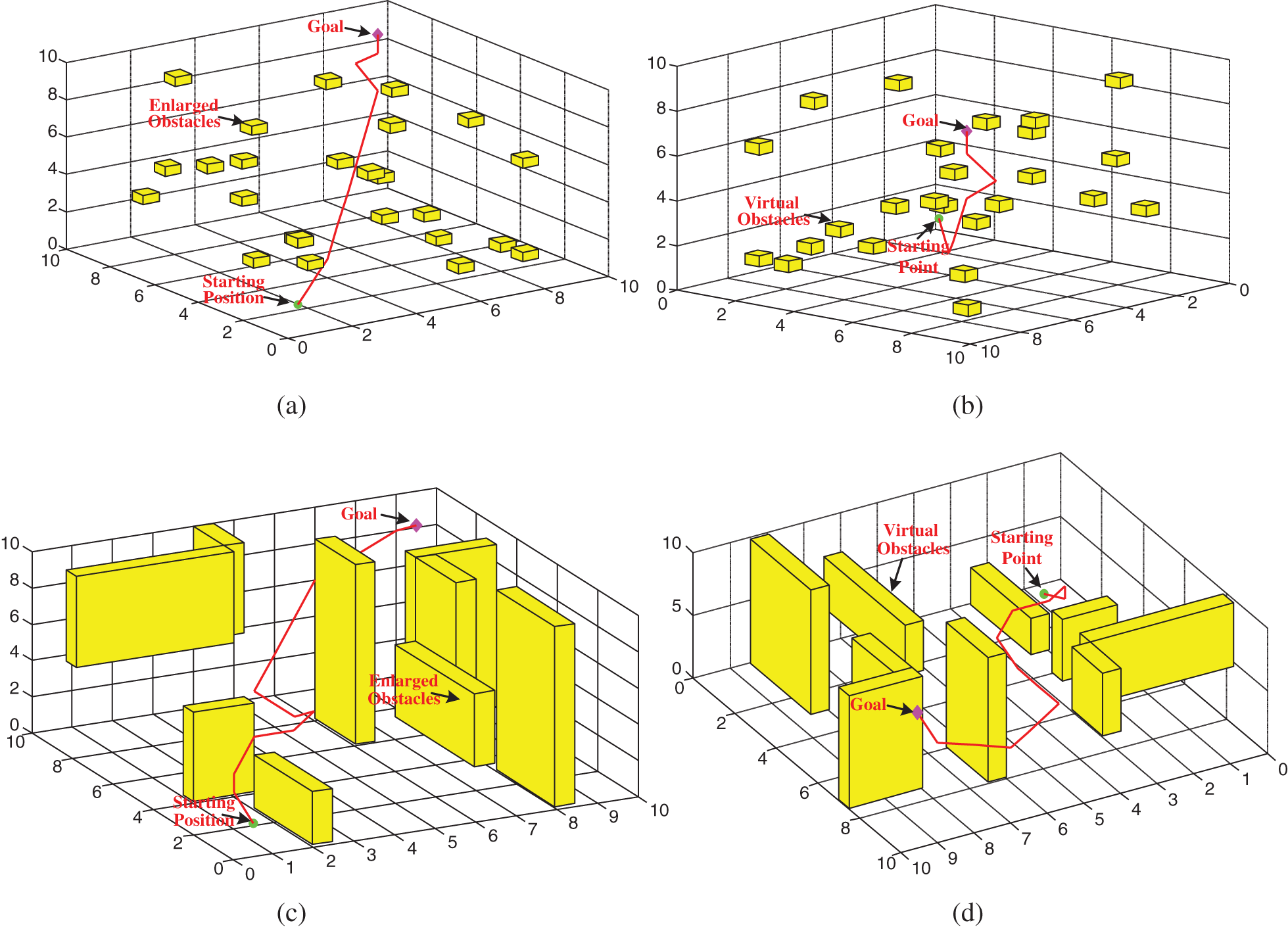
Figure 5: AUV path planning in 3D underwater environment with static goal (a) Front view of path planning in the disperse obstacles, (b) Back view of path planning in the disperse obstacles, (c) Front view of path planning in the narrowness of roads, (d) Back view of path planning in the narrowness of roads
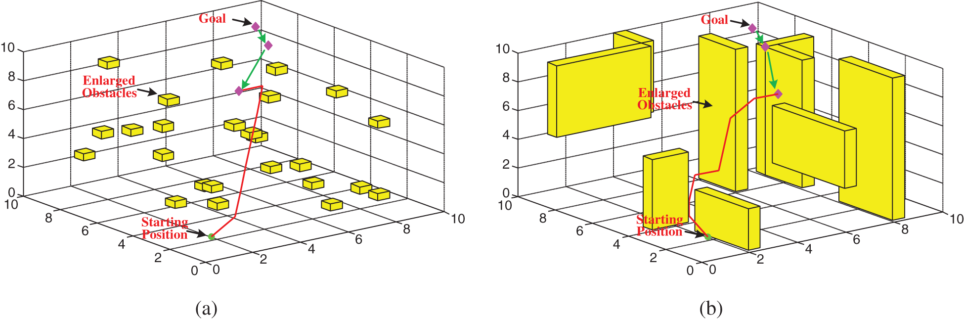
Figure 6: AUV path planning in a 3D underwater environment with a dynamic goal (a) The disperse obstacles, (b) The narrowness of roads
Owing to the influence of water currents, not only static and dynamic obstacles exist in the underwater environment. The proposed algorithm must avoid not only static obstacles but dynamic obstacles as well. The initial locations for the AUV, goal location, and obstacles are depicted in Fig. 7a, where O1 and O2 are dynamic obstacles. The movement speeds of the dynamic obstacle are lower than those of the AUV. At the beginning of the stage, with no obstacle, around the AUV, the AUV moves towards the goal. However, in this simulation the obstacle O1 moves to the planning path of the AUV. If the AUV continuously traverses along the original trajectory, a collision with O1 would occur. However, such a problem can be solved by the proposed algorithm, as can adjust the AUV’s next motion direction according to the PBNN of real-time change. The AUV can change its moving directions to by-pass the dynamic obstacle. Similarly, if the obstacle O2 moves toward the path of AUV, the proposed algorithm will re-plan a collision-free path to by-pass it. Fig. 7b shows the trajectories that were re-planned during the path planning process.
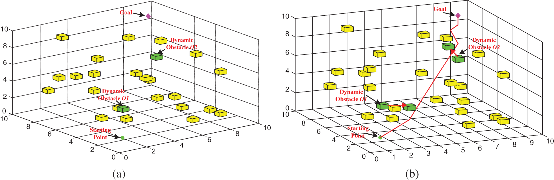
Figure 7: AUV path planning in a 3D underwater environment with dynamic obstacles (a) The initial state, (b) Final trajectories
4.3 Comparison of Different Algorithms
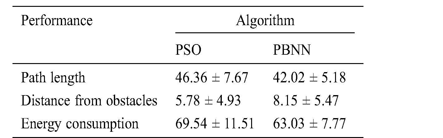
The proposed algorithm is expected to improve the efficiency of path planning under the condition of the AUV navigating safely in the underwater environment compared with another commonly used algorithm, such as the PSO algorithm. The comparison studies involve one dynamic goal and some obstacles with a 3D underwater environment scale of  . The goal position, AUV, and obstacles are randomly deployed. Two algorithms are applied to the AUV that is directed to path planning. Under these conditions, two algorithms separately complete 50 simulation experiments of path planning. To make a clear distinction between the two algorithms, Tab. 2 lists the mean and standard deviation statistics of path length, distance from the AUV to the obstacle, and energy consumption by both algorithms. It is reasonable to conclude that the integrated PBNN algorithm performs better than the PSO algorithm in each item of simulation results. Hence, it distinguishes itself from the shorter path length and time and lower energy consumption. By analysis, since the PSO algorithm only considers a local optimal, the generated path may not prevent an AUV from approaching obstacles “too close”. Owing to the generated path perhaps not being in accord with the restriction that the length of the path should be short to the greatest extent when the approach is applied in point-to-point path planning, the path is the “too far”. However, the PBNN can not only perform the secure path planning but also plan shorter paths. Thus, the PBNN approach for AUV path planning with safety consideration is capable of planning a real-time “comfortable” trajectory by overcoming the either “too close” or “too far” shortcoming.
Table 2: Comparison of performance with two different algorithms in the 3D underwater environment
The performance of the proposed algorithm was tested in a real pool environment, using the Neptune-1 AUV model (see Fig. 8). The model is based on a remote submarine produced by Thunder-Tiger. The model was made into an AUV by adding a positioning module and rebuilding the remote-control system. The AUV thruster has a speed of 2 knots or 1.08 kN. Since underwater acoustic communication is not yet mature, this experiment was carried out on the water’s surface. The AUV communicated using WiFi.
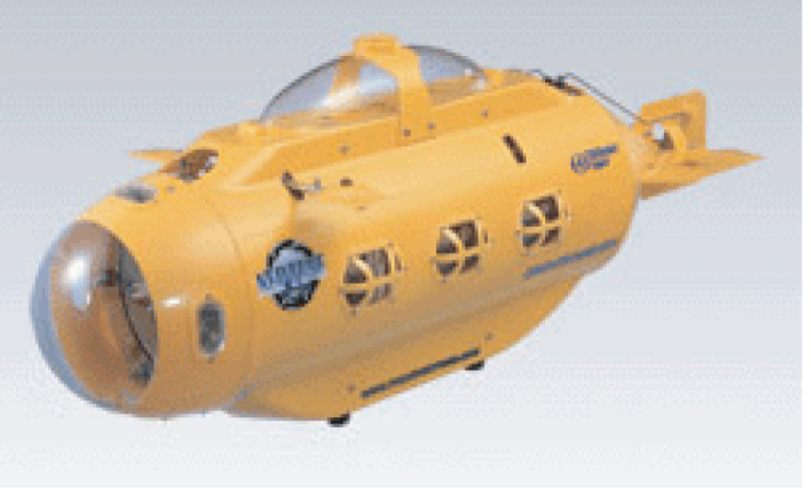
Figure 8: AUV model
The AUV position information is obtained through the water surface control platform, and the navigation path of the AUV plotted. Fig. 9 shows the path-planning experiment conducted by the Neptune-1 AUV in the pool with an obstacle. A remotely operated vehicle was placed into the pool as an obstacle. At the beginning of the experiment, the AUV navigated to the target along the path of bio-inspired neural network planning. The goal random motion. Next, when approaching the obstacle, the AUV kept a safe distance from the obstacle according to the potential field function to avoid a collision. Finally, the AUV reached the target along the collision-free planning path, which was similar to the path obtained in simulations. Therefore, the effectiveness of the proposed algorithm is verified by this experiment.
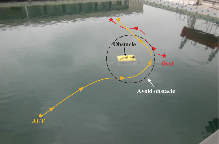
Figure 9: Pool experiment
In this study, a novel potential field bio-inspired neural network methodology is proposed to realize AUV path planning for static and dynamic goals in an underwater environment with obstacles. A real-time safety aware navigation paradigm was developed for the guidance of the AUV locally to plan more reasonable and safer trajectories. Simulations and experimental study validated that the proposed approach was capable of performing safety aware navigation of an AUV. Despite the advantages of this algorithm, some problems were still insufficiently considered. In the future, the proposed algorithm’s robustness and resilience [46] will be studied. While the concept of robustness seems to be well known, the concept of the resilience of an operation system, that is a path-planning system in this case, has been less discussed. The resilience of a path planning and scheduling system means that such a system can recover its ability to function after the system incurs partial damage. The five principles that can improve the resilience of a robotic system will be considered [47,48].
Funding Statement: This project is supported by the National Natural Science Foundation of China (61773177), the Natural Science Foundation of Jiangsu Province (BK20171270), the China Postdoctoral Science Foundation (2017M621587) and the Jiangsu Planned Projects for Postdoctoral Research Funds (1701076B).
Conflicts of Interest: The authors declare that they have no conflicts of interest to report regarding the present study.
1. C. Huang and J. Fei. (2018). “UAV path planning based on particle swarm optimization with global best path competition,” International Journal of Pattern Recognition and Artificial Intelligence, vol. 32, no. 6, pp. 1859008. [Google Scholar]
2. D. Q. Zhu, X. Cao, B. Sun and C. M. Luo. (2018). “Biologically inspired self-organizing map applied to task assignment and path planning of an AUV system,” IEEE Transactions on Cognitive and Developmental Systems, vol. 10, no. 2, pp. 304–313. [Google Scholar]
3. X. Cao, C. Y. Sun and M. Z. Chen. (2019). “Path planning for autonomous underwater vehicle in time-varying current,” IET Intelligent Transport Systems, vol. 13, no. 8, pp. 1265–1271. [Google Scholar]
4. X. Cao, H. C. Yu and H. B. Sun. (2019). “Dynamic task assignment for multi-AUV cooperative hunting,” Intelligent Automation & Soft Computing, vol. 25, no. 1, pp. 25–34. [Google Scholar]
5. R. K. He, R. X. Wei and Q. R. Zhang. (2017). “UAV autonomous collision avoidance approach,” Automatika, vol. 58, no. 2, pp. 195–204. [Google Scholar]
6. B. J. Chang, B. H. Yu and Y. H. Liang. (2017). “Colouring vehicle threat and minimising threat avoidance trajectory cost for adaptive vehicle collision defence system in active safe driving,” IET Intelligent Transport Systems, vol. 11, no. 6, pp. 309–318. [Google Scholar]
7. X. Cao and C. Y. Sun. (2017). “A potential field-based PSO approach to multi-robot cooperation for target search and hunting,” At-Automatisierungstechnik, vol. 65, no. 12, pp. 878–887. [Google Scholar]
8. C. Shen, Y. Shi and B. Buckham. (2017). “Integrated path planning and tracking control of an AUV: A unified receding horizon optimization approach,” IEEE/ASME Transactions on Mechatronics, vol. 22, no. 3, pp. 1163–1173. [Google Scholar]
9. C. Hofner and G. Schmidt. (1995). “Path planning and guidance techniques for an autonomous mobile robot,” Autonomous System, vol. 14, no. 2, pp. 199–212. [Google Scholar]
10. G. Schmidt and C. Hofner. (1998). “An advanced planning and navigation approach for autonomous cleaning robot operation,” in IEEE Int. Conf. on Intelligent Robots System. Victoria, BC, Canada, pp. 1230–1235. [Google Scholar]
11. Y. Liu, S. Q. Zhu, B. Jin, S. S. Feng and H. F. Gong. (2004). “Sensory navigation of autonomous cleaning robots,” in 5th World Conf. on Intelligent Control Automation. Hangzhou, China, pp. 4793–4796. [Google Scholar]
12. R. N. De Carvalho, H. A. Vidal, P. Vieira and M. I. Ribeiro. (1997). “Complete coverage path planning and guidance for cleaning robots,” IEEE Int. Conf. Industry Electronics, vol. 2, pp. 677–682. [Google Scholar]
13. A. Ram and J. C. Santamaria. (1997). “Continuous case-based reasoning,” Artificial Intelligence, vol. 90, no. 2, pp. 25–77. [Google Scholar]
14. A. Arleo, F. Smeraldi and W. Gerstner. (2004). “Cognitive navigation based on non-uniform Gabor space sampling, unsupervised growing networks, and reinforcement learning,” IEEE Transaction on Neural Network, vol. 15, no. 3, pp. 639–652. [Google Scholar]
15. Y. B. Chen, G. C. Luo, Y. S. Mei, J. Q. Yu and X. L. Su. (2016). “UAV path planning using artificial potential field method updated by optimal control theory,” International Journal of Systems Science, vol. 47, no. 6, pp. 1407–1420. [Google Scholar]
16. C. Rathgeber, F. Winkler and S. Mueller. (2016). “Collisionfree longitudinal and lateral trajectory planning considering vehicle-dependent potentials,” At-Automatisierungstechnik, vol. 64, no. 1, pp. 61–76. [Google Scholar]
17. M. Radmanesh, M. Kumar, A. Nemati and M. Sarim. (2016). “Dynamic optimal UAV trajectory planning in the national airspace system via mixed integer linear programming,” in Proc. of the Institution of Mechanical Engineers, Part G: Journal of Aerospace Engineering, vol. 230, no. 9, pp. 1668–1682. [Google Scholar]
18. J. Park, S. Karumanchi and K. Iagnemma. (2015). “Homotopy-based divide-and-conquer strategy for optimal trajectory planning via mixed-integer programming,” IEEE Transactions on Robotics, vol. 31, no. 5, pp. 1101–1115. [Google Scholar]
19. Y. Rasekhipour, A. Khajepour, S. K. Chen and B. Litkouhi. (2017). “A potential field-based model predictive path-planning controller for autonomous road vehicles,” IEEE Transactions on Intelligent Transportation Systems, vol. 18, no. 5, pp. 1255–1267. [Google Scholar]
20. J. Berger, A. Boukhtouta, A. Benmoussa and O. Kettani. (2012). “A new mixed-integer linear programming model for rescue path planning in uncertain adversarial environment,” Computers & Operations Research, vol. 39, no. 12, pp. 3420–3430. [Google Scholar]
21. Z. Wang, S. Zlatanova and P. V. Oosterom. (2017). “Path planning for first responders in the presence of moving obstacles with uncertain boundaries,” IEEE Transactions on Intelligent Transportation Systems, vol. 99, pp. 1–11. [Google Scholar]
22. S. Uttendorf, B. Eilert and L. Overmeyer. (2017). “Combining a fuzzy inference system with an A* algorithm for the automated generation of roadmaps for automated guided vehicles,” at-Automatisierungstechnik, vol. 65, no. 3, pp. 189–197. [Google Scholar]
23. S. A. Bortoff. (2002). “Path planning for UAVs,” in Proc. of the American Control Conf., IEEE, pp. 364–368. [Google Scholar]
24. Q. Wang, M. Langerwisch and B. Wagner. (2013). “Wide range global path planning for a large number of networked mobile robots based on generalized Voronoi diagrams,” in IFAC Proc., vol. 46, no. 29, pp. 107–112. [Google Scholar]
25. R. Cui, Y. Li and W. Yan. (2016). “Mutual information-based multi-AUV path planning for scalar field sampling using multidimensional RRT,” IEEE Transactions on Systems, Man, and Cybernetics: Systems, vol. 46, no. 7, pp. 993–1004. [Google Scholar]
26. J. Kim and S. H. Woo. (2018). “Reference test maps for path planning algorithm test,” International Journal of Control Automation and Systems, vol. 16, no. 1, pp. 397–401. [Google Scholar]
27. T. Zaid, A. H. Qureshi, A. Yasar and N. Raheel. (2018). “Potentially guided bidirectionalized RRT* for fast optimal path planning in cluttered environments,” Robotics and Autonomous Systems, vol. 108, pp. 13–27. [Google Scholar]
28. R. A. Romero, E. Prestes, M. A. Idiart and G. Faria. (2012). “Locally oriented potential field for controlling multi-robots,” Communications in Nonlinear Science and Numerical Simulation, vol. 17, no. 12, pp. 4664–4671. [Google Scholar]
29. H. Qu, K. Xing and T. Alexander. (2013). “An improved genetic algorithm with co-evolutionary strategy for global path planning of multiple mobile robots,” Neurocomputing, vol. 120, pp. 509–517. [Google Scholar]
30. Z. Wang and J. J. Cai. (2018). “The path-planning in radioactive environment of nuclear facilities using an improved particle swarm optimization algorithm,” Nuclear Engineering and Design, vol. 326, pp. 79–86. [Google Scholar]
31. X. Wang, Y. Shi, D. Ding and X. Gu. (2016). “Double global optimum genetic algorithm-particle swarm optimization-based welding robot path planning,” Engineering Optimization, vol. 48, no. 2, pp. 299–316. [Google Scholar]
32. J. Lee. (2017). “Heterogeneous-ants-based path planner for global path planning of mobile robot applications,” International Journal of Control Automation and Systems, vol. 15, no. 5, pp. 1–16. [Google Scholar]
33. X. Cao and D. Q. Zhu. (2015). “Multi-AUV underwater cooperative search algorithm based on biological inspired neurodynamics model and velocity synthesis,” Journal of Navigation, vol. 68, no. 6, pp. 1075–1087. [Google Scholar]
34. S. X. Yang and C. M. Luo. (2004). “A neural network approach to complete coverage path planning,” IEEE Transactions on Systems, Man, and Cybernetics, Part B, vol. 34, no. 1, pp. 718–725. [Google Scholar]
35. X. Cao and D. Q. Zhu. (2017). “Multi-AUV task assignment and path planning with ocean current based on biological inspired self-organizing map and velocity synthesis algorithm,” Intelligent Automation & Soft Computing, vol. 23, no. 1, pp. 31–39. [Google Scholar]
36. X. Hu, L. Chen, B. Tang, D. Cao and H. He. (2018). “Dynamic path planning for autonomous driving on various roads with avoidance of static and moving obstacles,” Mechanical Systems and Signal Processing, vol. 100, pp. 482–500. [Google Scholar]
37. T. Zhang, W. Y. Louie, N. Goldie and B. Beno. (2018). “Robot imitation learning of social gestures with self-collision avoidance using a 3D sensor,” Sensors, vol. 18, no. 7, pp. 2355. [Google Scholar]
38. S. Grossberg. (1988). “Nonlinear neural networks: Principles, mechanisms, and architectures,” Neural Networks, vol. 1, no. 1, pp. 17–61. [Google Scholar]
39. A. L. Hodgkin and A. F. Huxley. (1952). “A quantitative description of membrane current and its application to conduction and excitation in nerve,” Journal of Physiology, vol. 117, no. 4, pp. 500–544. [Google Scholar]
40. X. Cao, D. Q. Zhu and S. X. Yang. (2016). “Multi-AUV cooperative target search based on biological inspired neurodynamics model in 3-D underwater environments,” IEEE Transactions on Neural Networks and Learning Systems, vol. 27, no. 11, pp. 2364–2374. [Google Scholar]
41. X. Cao and D. Q. Zhu. (2017). “Multi-AUV task assignment and path planning with ocean current based on biological inspired self-organizing map and velocity synthesis algorithm,” Intelligent Automation & Soft Computing, vol. 23, no. 1, pp. 31–39. [Google Scholar]
42. C. M. Luo and S. X. Yang. (2008). “A bioinspired neural network for real-time concurrent map building and complete coverage robot navigation in unknown environments,” IEEE Transactions on Neural Networks, vol. 19, no. 7, pp. 1279–1298. [Google Scholar]
43. J. Ji, A. Khajepour, W. W. Melek and Y. Huang. (2017). “Path planning and tracking for vehicle collision avoidance based on model predictive control with multiconstraints,” IEEE Transactions on Vehicular Technology, vol. 66, no. 2, pp. 952–964. [Google Scholar]
44. R. A. Romero, E. Prestes, M. A. Idiart and G. Faria. (2012). “Locally oriented potential field for controlling multi-robots,” Communications in Nonlinear Science and Numerical Simulation, vol. 17, no. 12, pp. 4664–4671. [Google Scholar]
45. D. H. Zhang, Y. M. Chen, C. Huang and M. K. Gao. (2016). “Improved path planning algorithm on the rugged road,” Automatika, vol. 57, no. 2, pp. 477–483. [Google Scholar]
46. W. J. Zhang and C. V. van Luttervelt. (2011). “Toward a resilient manufacturing system,” CIRP Annals, vol. 60, no. 1, pp. 469–472. [Google Scholar]
47. T. Zhang, W. J. Zhang and M. M. Gupta. (2017). “Resilient robots: Concept, review, and future directions,” Robotics, vol. 6, no. 4, pp. 22. [Google Scholar]
48. F. Wang, Z. Q. Qian, Z. G. Yan, C. W. Yuan and W. J. Zhang. (2019). “A novel resilient robot: Kinematic analysis and experimentation,” IEEE Access, vol. 8, pp. 2885–2892. [Google Scholar]
 | This work is licensed under a Creative Commons Attribution 4.0 International License, which permits unrestricted use, distribution, and reproduction in any medium, provided the original work is properly cited. |