DOI:10.32604/iasc.2021.015065
| Intelligent Automation & Soft Computing DOI:10.32604/iasc.2021.015065 | |
| Article |
Building Information Modeling Based Automated Building Regulation Compliance Checking Asp.net Web Software
Faculty of Architecture, Department of Architecture, Istanbul Technical University, Istanbul, 34367, Turkey
*Corresponding Author: Murat Aydın. Email: aydinmurat12@itu.edu.tr
Received: 05 November 2020; Accepted: 11 January 2021
Abstract: Building regulations used in the architecture, engineering, and construction sectors are legal documents prepared under the control of local authorities for use by individuals. These regulations determine the conditions for ensuring performance and quality throughout the entire construction process. The building regulation inspection process conducted with the traditional manual method is time-consuming and error-prone for architects, engineers, and local authorities. It is known that most of these inspections are carried out with municipalities by local authorities. The mutual interview study and literature review shows that there is no standard rule for the legal auditing process and the same services are defined differently by different municipalities. The aim of the study is to create building information modeling based automated building regulation compliance checking software (BIMTRAC3) for municipality users, thereby providing an automated code compliance checking (ACCC) process for housing projects according to the Planned Areas Zoning Regulation in Turkey. It includes a rule-based ACCC method which allows for simultaneous computerized code checking that considers the characteristics of the building elements and the relevant building regulations. It is able to perform the ACCC process and send the ACCC result report of the sample housing project by BIMTRAC3. It provides various solutions for problems experienced by municipalities during the ACCC process.
Keywords: Asp.net web software; automated code compliance checking; building information modeling; MVC architectural pattern; C# programming language
Nomenclature
| ACCC: | automated code compliance checking |
| BIM: | building information modeling |
| CU: | contractor user |
| MU: | municipality user |
| MVC: | model, view, and controller |
The building production process begins with the selection of an appropriate construction site, followed by design and planning, material production and use, and inspection and construction. In addition to the direct participation of the owner, architect, and contractor, municipalities are among the local authorities which exert a strong influence on the building construction process, especially in the case of high-cost construction. In particular, municipalities play a lead role in ensuring compliance with zoning rules and building regulations within the borders of the municipality as well as in adjacent areas.
The Planned Areas Zoning Regulation—published in the Official Gazette dated 2017.07.03—describes the terms and requirements determined by municipalities for the building production process. The purpose of the regulation is to convey the procedures and principles for building and construction, as well as to ensure that planning and inspection are undertaken in accordance with scientific, health, and sustainable environmental standards. One of the most important regulatory tasks performed by municipalities is the granting of construction permits to contractors operating in the private sector in Turkey. This permit is required for initiating a housing project. Municipalities also issue building use permits, which are required in order to obtain a residence permit upon the completion of a housing project in compliance with the building regulation.
In order to be issued a construction and/or building use permit, contractors must design and build in accordance with the relevant standards and regulations. Whether or not the building is designed and built-in accordance with the applicable standards and regulations is determined by local authorities through legal inspection tools during the building production process. Most of these inspections are conducted by municipalities within local authorities. According to studies based on interviews with municipalities, building regulation, control, and inspection processes are most often performed manually using traditional methods. These methods are time-consuming, lasting for ten days on average for a construction permit service and seven days for a building use permit service. They are also error-prone, and lead to misconduct arising from manual code checking, time loss due to poorly planned/described similar process steps in building regulation checking, failure to follow a wide-range of numerous building regulations, and inconsistency between updated building regulations and regulation clauses.
The literature review in the fields of building information modeling (BIM) and automated code compliance checking (ACCC) shows that most studies highlight the need for standardization and automation to address problems in building regulation checking [1–6]. In most of the studies, the necessity of BIM-based ACCC through computers has come to the forefront [7–12]. Many studies have emphasized the importance of the development of national building regulation checking software to minimize the problems encountered in ACCC [13–17].
Although performed in a variety of countries, studies show similarities in the problems experienced in building regulation checking across different countries, including Turkey. However, in Turkey, most studies have been limited to the subjects of process improvement and geographic information systems in municipalities [18,19]. It has been noted that although the construction sector is highly active in Turkey as compared to other countries, studies in the field of ACCC for municipalities are still not sufficient.
During nine interviews held with personnel responsible for construction permit and building use permit services in Uskudar Municipality, Atasehir Municipality, Kadikoy Municipality, Besiktas Municipality, Sisli Municipality, and Zeytinburnu Municipality (all of which have a higher population and housing density than many other districts in Istanbul) the necessity of ACCC software for municipalities in Turkey was frequently emphasized. The aim of the study was to establish BIM-based BIMTRAC3 software for municipality users providing an automated code compliance checking process for housing projects in Turkey in accordance with the Planned Areas Zoning Regulation based on the literature review and current situation analysis. The ACCC method used in the study is described in Section 2. The MVC structure of BIMTRAC3, which is ASP.NET web software, and C# coding architecture are addressed in Section 3. BIMTRAC3 was tested on a sample housing project, as described in Section 4. The effect of code compliance checking based on BIMTRAC3 on the delay time (day) in construction permit and building use permit services is discussed in Section 5. The results and evaluations of the study are included in Section 6.
Building regulations used in the architecture, engineering, and construction sectors are legal documents prepared for use by individuals; these documents are controlled by local authorities. Building regulation checking and inspection processes conducted with manual traditional methods are time-consuming and error-prone for architects, engineers, and local authorities [20]. Therefore, BIM-based automated code compliance checking is considered a promising field of study. ACCC is a rule-based method for simultaneous computerized code checking that considers the characteristics of the building elements and the relevant codes. This method involves checking each building element for compliance with the rules and conditions of the relevant code, and reporting the results [21]. In the ACCC method, the building regulations are interpreted accurately, precisely, and clearly and then converted into building regulation rules in the computer environment [22]. ACCC software is developed to perform compliance checking of the established building regulation rules according to the BIM model of housing projects created via BIM-based software. Briefly, ACCC is comprised of the interpretation of building regulations, the establishment of building regulation rules, and the checking of the compliance of a housing project with building regulations by a computer.
BIMTRAC3 is a combination of the acronyms and/or abbreviations BIM, TR, and AC3 (ACCC). As understood from the term, BIMTRAC3 is BIM-based automated code compliance checking software for municipality users in Turkey. BIMTRAC3 is ACCC software for uploading a housing project to the database, selecting, and then visualizing it. Fig. 1 shows the name, logo, and motto of BIMTRAC3. The logo of BIMTRAC3 was designed to highlight the meaning of the green √ and red X signs signifying the results of ACCC. The expression ‘the smartest building code compliance checker’ was selected as the motto of BIMTRAC3.
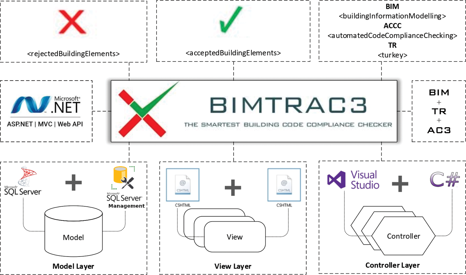
Figure 1: The concept of BIMTRAC3
BIMTRAC3 is web software with a design based on a combination of ASP.NET technology and the MVC architectural pattern. ASP.NET, developed as a free product of the Microsoft family, is preferred by software engineers to create easy, high-speed, and high-performance web software. ASP.NET web software is accessible to users over HTTP protocol, regardless of time, place, or location. As ASP.NET web software, BIMTRAC3 uses a web browser with internet access through a computer or a smartphone, which in turn has its own independent programming language and operating platform (such as Windows, Linux, Mac OS, Android, or iOS). The web server is installed on the server-side. Municipalities or contractors login to BIMTRAC3 by typing its internet address—www.bimtrac3.com.tr—in the address bar of the web browser and thereby enter the homepage. BIMTRAC3 is currently operated by a computer with “localhost:60819”. The goal is to purchase a domain for BIMTRAC3 after ensuring web security and protection of legal rights.
Consisting of the first letters of words ‘Model’, ‘View’, and ‘Controller’, MVC is defined as an architectural pattern used in software engineering. MVC was suggested by Tygve Reeskaug in 1979 and first applied in the Smalltalk software project conducted by Xerox Research Laboratory [23]. Today, MVC integrated with ASP.NET technology of the Microsoft company is preferred by many software engineers. Due to its layered structure, MVC facilitates the management, control, and synchronous operation of software projects. MVC is a software architectural pattern separating the back-end (where encodings of the software are performed) from the front-end (which is visible to users).
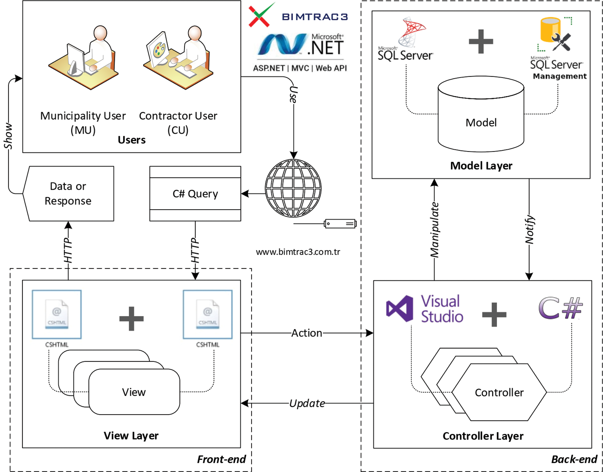
Figure 2: The MVC structure of BIMTRAC3
The MVC structure of BIMTRAC3 shown in Fig. 2 consists of the model, view, and controller layers. The model layer is where all the data, databases, and data lists of BIMTRAC3, as well as classes in the data lists, are saved, protected, and updated. The view layer is where views of BIMTRAC3 are created to be shown to the user. The controller layer controls and inspects the operations performed by the user in BIMTRAC3. The query from the user in the view layer of BIMTRAC3 (as shown in Fig. 2) is first transmitted to the controller layer, where it is processed. The operations to be applied (according to the criteria of the query) and the view to be shown as data to the user are evaluated at the controller layer. The query is then sent to the model layer and presented as data through the BIMTRAC3 database. The right data is transmitted from the model layer to the view layer through the controller layer. It is shown to the user as data or a response in the view layer, where the query was created.
The model layer of MVC is where the business logic in the software is created and the data are modeled. In addition to these important functions, validation, protection, update, and data access operations are also performed in this layer. The model layer in the MVC structure of BIMTRAC3 (as shown in Fig. 2) includes one BIMTRAC3 database (where all the data of BIMTRAC3 is stored), six BIMTRAC3 municipality databases, and fifteen data lists. The Microsoft SQL Server (MSSQL) database system, and in particular Microsoft SQL Server Management Studio (SSMS), used together with ASP.NET technology, was selected for the management of the BIMTRAC3 database and data flow optimization. SSMS provides users with an integrated work environment to develop, set, use, and manage the MSSQL database systems. Fig. 3 shows the structure of the BIMTRAC3 database created based on SSMS. SSMS software supports all necessary database operations, including updating, editing, modifying, deleting the BIMTRAC3 database, creating new data lists in the database, adding a new database, and saving new data in the database.
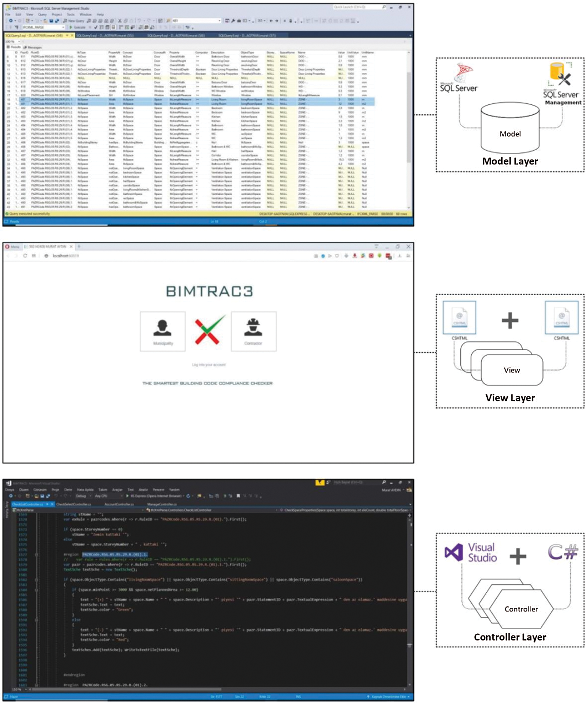
Figure 3: The model, view, and controller layers of BIMTRAC3
The view layer of MVC is the layer where the views visible to the user are created. The task of the view layer is to send the queries from software users and to show them as data in the right view. In the view layer of the MVC structure in BIMTRAC3 (as shown in Fig. 2) one homepage intended for users, four modules, and fifteen views were created. ASP.NET Web Page (CSHTML) programming language, together with ASP.NET technology (a Microsoft family product), was used for the views. CSHTML is a viewing tool based on ASP.NET technology available for the users. When creating a new software project, views in the view layer are defined as a web page with a “.cshtml” extension. Fig. 3 shows the homepage of BIMTRAC3 as a web page with a “.cshtml” extension.
The module was defined as a software layout containing one or more operations performed routinely in BIMTRAC3 for a particular purpose. Each module in BIMTRAC3 was developed independently of each other. As in many corporate-level software projects, four modules were created for BIMTRAC3. Each of these was designed to perform different and unique operations in BIMTRAC3. The modules of the BIMRAC3 software consisted of views interrelated within the module and each performed a particular operation intended for users. The modules in BIMTRAC3 and the views in the modules are shown in Fig. 8 with the operations performed.
The controller layer of MVC controls and inspects the operations performed by the user in the software. It is defined as the layer that provides communication between the model and view layers, receives the query created by the user through the view layer, and moves it to the model layer. Also evaluated at the controller layer are the appropriate operations to be applied according to the criteria of query and the view to be shown as data to the user. Therefore, it is the layer that functions as a bridge between the model and view layers and performs swap operations of the data. In the controller layer of the MVC structure in BIMTRAC3 shown in Fig. 2, fifteen controllers for queries created by the user and three components to perform defined operations were created.
Microsoft Visual Studio (VS) software providing ASP.NET technology (a basic product of the Microsoft family) was used for controllers created in the controller layer of the MVC structure of BIMTRAC3. VS (as shown in Fig. 3) is an integrated development environment produced by Microsoft. VS software is used for desktop and web software with C# programming language. Its community version is freely available to users for the development of individual software and was selected for BIMTRAC3.
3.2 C# Coding Architecture of BIMTRAC3
BIMTRAC3 was designed as a rule-based software to perform automated code compliance checking for housing projects in Turkey in accordance with the Planned Areas Zoning Regulation. C# programming language was used in VS software to code the statements of the related clauses for the selected building elements from the Planned Areas Zoning Regulation as a rule. The if-else control structure in C# programming language was used to make the condition for building elements in the statement readable and controllable by BIMTRAC3. In the if-else control structure, at least one condition was stated to control a rule. If there was more than one condition for the building element, a nested if-else control structure was used. Operations to be performed in case one or more conditions are met were written separately. The C# coding architecture was made up of three parts based on the if-else control structure to code the statements of the clauses in the Planned Areas Zoning Regulation as a rule. In the controller layer of the MVC structure of BIMTRAC3, a total of 50 rules were coded in C# programming language according to the if-else control structure, including fifteen for spaces (room or zone), eight for doors, six for windows, two for railings, one for lighting and air ventilation shafts, eleven for elevators and seven for stairs.
Fig. 4 shows the first section of C# coding architecture according to the if-else control structure of a rule. The definition of the building element in the BIM model where the condition in the rule statement for the first condition of the if-else control structure would be applied was individually coded. The rule statement was clearly expressed in the first Substatement under Statement 1 in Clause 29 (Building Spaces and Sizes) in the Fifth Part of the Planned Areas Zoning Regulation: “Space: The narrow edge of a living room cannot be less than 3.00 meters, and its net area cannot be less than 12.00 square meters.” livingRoomSpace, sittingRoomSpace, and saloonRoomSpace were selected for the meaning of the condition in the rule statement in C# programming language. The definition of each selected building element was individually associated with the command line space.ObjectType.Contains in brackets with the selection from C# coding. Each command line was ended with || (or) statement in C# coding language.
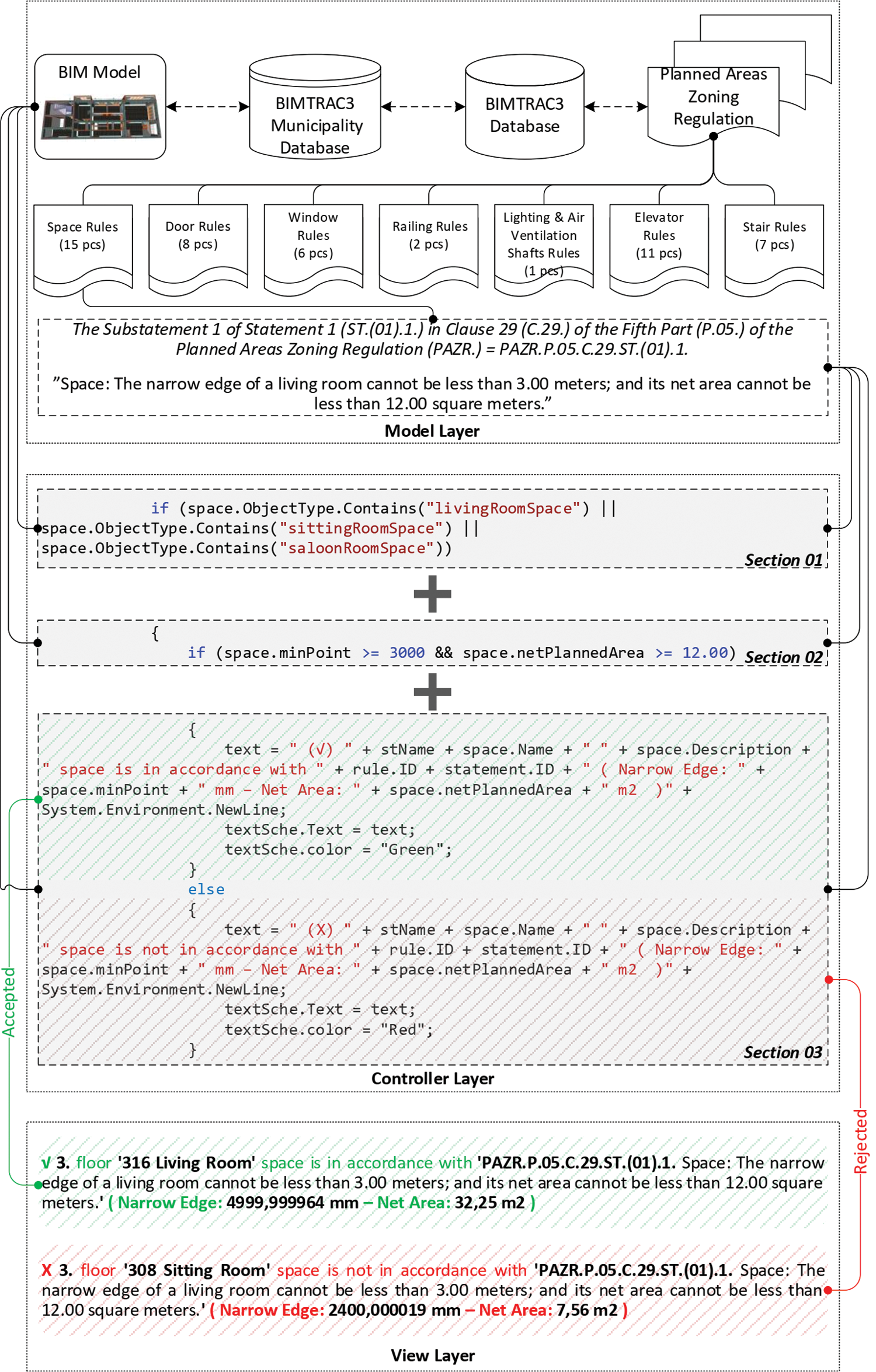
Figure 4: The C# coding architecture of BIMTRAC3
Fig. 4 shows the second section of C# coding architecture according to the if-else control structure of a rule. The requirements to be met by the building element in the BIM model (where the condition in the rule statement for the second condition of the if-else control structure would be applied) were coded. This rule statement expressed the condition that the narrow edge of one living room cannot be less than 3.00 meters and the net area cannot be less than 12 square meters. The living room where the condition in the rule statement would be applied was not re-checked since it was selected in the first section of the C# coding architecture. A second if command was selected from the C# coding architecture, and then space.minPoint and space.netPlannedArea commands (being equivalent in the C# programming language) specifying the narrow edge and the net area of the living room in parenthesis were entered. The numerical value of the space.minPoint command was defined as 3000 and of the space.netPlannedArea command as 12.00. Both commands were associated with the ≥ (greater than or equal to) mathematical operator. The second condition was completed by inserting the && (and) sign in the C# coding language between both commands. Since standard units of measurement were used in the characteristics of the BIM model such as length, area, volume, etc., they were not respecified within the condition.
Fig. 4 shows the third section of C# coding architecture according to the if-else control structure of a rule. This section addresses the operations to be performed if the condition in the first and second section of the nested if-else control structure is true or any of them is false. For the operations to be performed, the command operation is resumed using the else command in the C# coding. A standard text format is created in the C# coding language for the true or false operations to be applied with the else command. The standard text format is a text print or text output consisting of green and red colors depending on the check results of both conditions. If the characteristics of the building element defined in the BIM model fulfill both conditions specified in the if commands, the standard green text starting with the √ sign is written. Unless it fulfills one or two conditions specified in the if commands, the red standard text starting with the X sign is written.
The standard text format shown in Fig. 4 is divided into the following four sections:
• The information on the building floor where the building element in the BIM model checked by condition and located in the housing project was obtained with the stName command line.
• The information on the name of the building element in the BIM model checked by condition was obtained with the space.Name command line and the description information with the space.Description command line.
• The information on the check rule of the building element in the BIM model checked by condition was obtained with the rule.ID command line and the rule statement with the statement.ID command line.
• Many different command lines were used for the characteristics of the building element in the BIM model checked by condition. The command lines used varied depending on the characteristics of the building element that was checked by the second condition of the if-else control structure created in the second section of the C# coding architecture.
Within the scope of the study, a sample housing project was modeled to be checked in BIMTRAC3. BIM-based ArchiCAD software was used for the BIM model of the housing architectural project. A sample contractor was created who was responsible for the construction services of the housing project. The process was initiated by creating a new project from the ArchiCAD for the BIM model of the housing project. The floor and project data of the housing project were entered. For the housing project, various types of building elements such as rooms, doors, windows, railings, mechanical ventilations, elevators, stairs, walls, columns, beams, and slabs were modeled. The BIM model of the sample housing project is shown in Fig. 5.
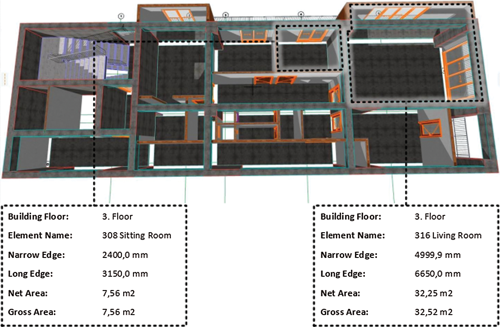
Figure 5: The BIM model of the sample housing project
Regarding the use of BIMTRAC3 shown in Fig. 8, the web address www.bimtrac3.com.tr was typed in the address bar of a web browser providing internet access via a computer or a smartphone incorporating an operating platform; the BIMTRAC3 homepage was then accessed. Two types of users were allowed to log in via the BIMTRAC3 homepage. These were the municipality user (MU) and the contractor user (CU). The contractor button on the BIMTRAC3 homepage shown in Fig. 3 was clicked for the CU to start using BIMTRAC3. The CU typed the username and password in the available spaces, then clicked the login button and entered BIMTRAC3. The username and password of the CU were controlled, and the following operations were performed in BIMTRAC3:
• Logging into BIMTRAC3 by the CU (BIMTRAC3 Homepage),
• Uploading the project to the BIMTRAC3 municipality database (File View).
After the upload, the CU clicked the logout button and logged out of BIMTRAC3. The data file of the housing project was uploaded to the Kadikoy Municipality’s database. The CU, who is responsible for performing the construction services, submitted the housing architectural project to the Kadikoy Municipality Zoning and Urbanization Directorate according to the Planned Areas Zoning Regulation.
As shown in Fig. 8, the MU clicked the municipality button on the BIMTRAC3 homepage shown in Fig. 3 to use BIMTRAC3. The MU typed the username and password in the available space, then clicked the login button and entered BIMTRAC3. Within the scope of the study, it was considered that Kadikoy Municipality Zoning and Urbanization Directorate, Zoning and Urbanization Deputy Manager, Civil Engineer, Hasan Tan, checked and approved the sample housing architectural project according to the Planned Areas Zoning Regulation. The username and password of the MU were controlled, and the following operations were performed in BIMTRAC3, respectively:
• Logging into BIMTRAC3 by MU (BIMTRAC3 Homepage),
• Selection of the project (File Module),
Selection of the project from the BIMTRAC3 municipality database (File View),
• Review of the building regulations (Building Regulations View),
• Review of the building regulation codes (Building Regulation Codes View), and
• Logging into BIMTRAC3 by the rule manager user (Rule Manager View).
• Visualization of the project (Model Module),
Creation of the tree data structure (Model Tree Data View),
• Creation of the three-dimensional view (Model 3D View),
• Creation of the project information (Project Info View), and
• Creation of the quantity take-off of the building elements (Quantity Take-off View).
• Performance of the ACCC process of the project (Checking Module), and
Selection of the ACCC type (Code Checking View),
• Creation of the ACCC result (Checking Result View),
• Creation of the ACCC result report (Results Summary View), and
• Creation of the code controller information of the ACCC performed (Code Checker Info View).
• Communication of the project’s ACCC result report (Communication Module).
Sending the ACCC result report via e-mail (E-mail View).
The municipality user is authorized as a code checker to send the ACCC result report performed in BIMTRAC3 via e-mail. In the E-mail view, the ACCC result report is submitted to the CU by the MU. If the ACCC result report shown in Fig. 6 consists of green statements starting with the √ sign, the housing project uploaded to the BIMTRAC3 municipality database by the CU has been accepted by the MU. If the ACCC result report consists of red statements starting with the X sign, the housing project uploaded to the BIMTRAC3 municipality database by CU was not accepted by the MU. The CU updates the housing project according to the ACCC result report, and the operations in Fig. 8 are repeated until the ACCC result report starting with the √ sign is obtained. Within the scope of the study, the MU, Hasan Tan, successfully sent the BIMTRAC3 ACCC result report for the sample housing project to the CU via e-mail in PDF format. After the ACCC result report was sent via e-mail, the MU clicked the logout button on the E-mail view and logged out of BIMTRAC3.
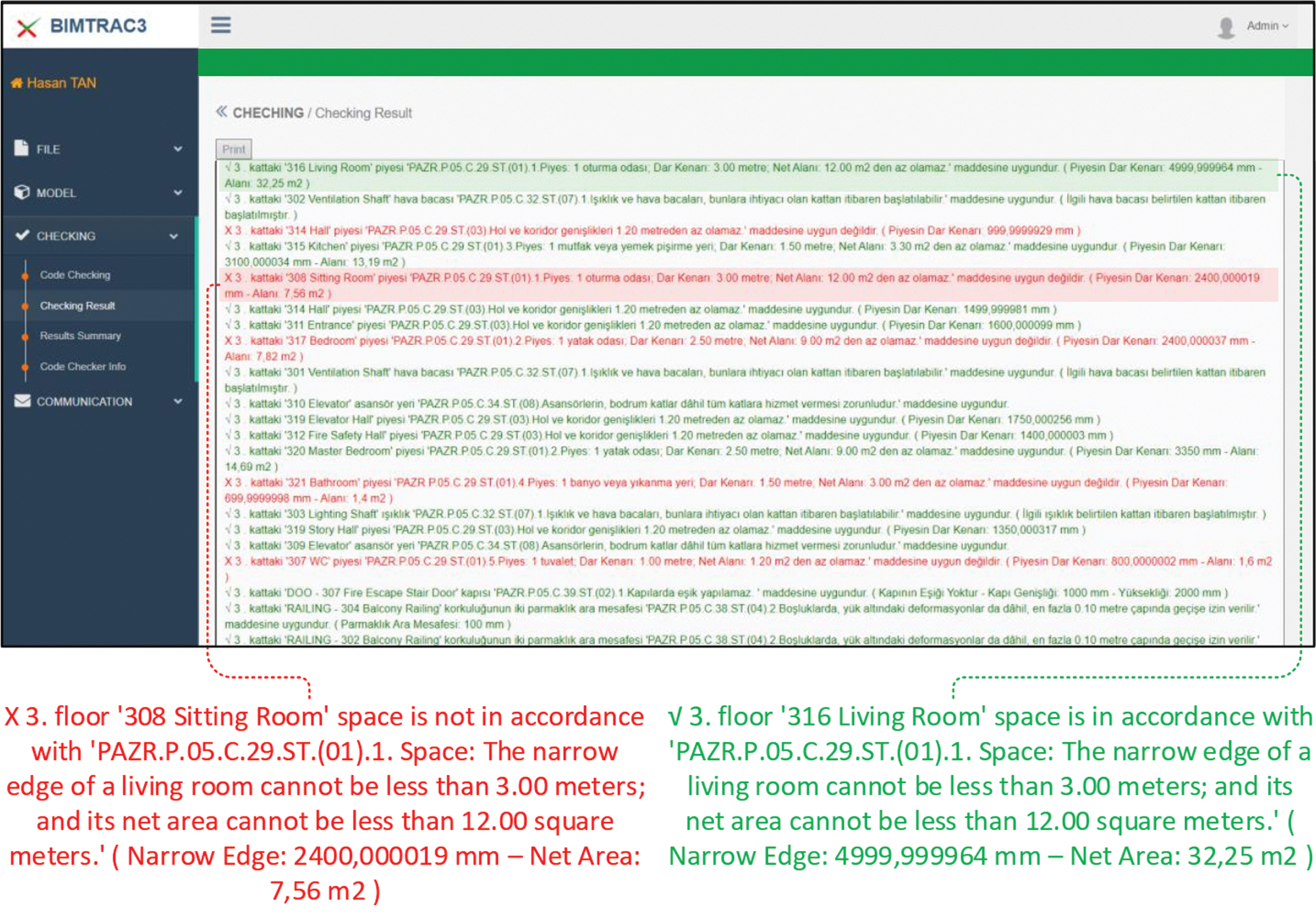
Figure 6: The checking result view of the checking module of BIMTRAC3
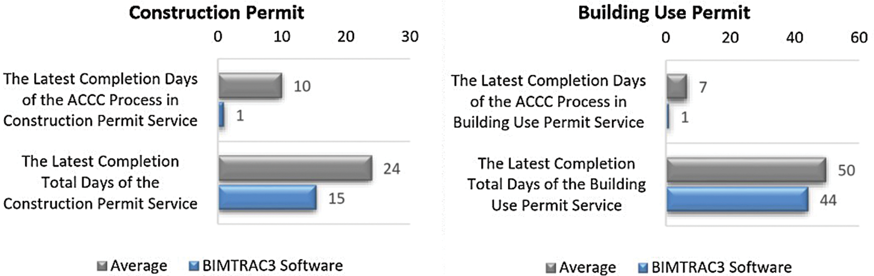
Figure 7: The distribution of the latest completion days of construction permit and building use permit services with BIMTRAC3
The study was based on nine interviews with six municipalities which were conducted in order to demonstrate and analyze the general status of ACCC in construction permit and building use permit services provided by the municipalities. According to the results of the interviews (as shown in Fig. 7), the ACCC process when conducted using manual methods typically took about ten days in construction permit services and seven days in building use permit services. In comparison, as shown in Fig. 7, the ACCC process in both services can be completed by municipalities in one day through BIMTRAC3. Therefore, the completion period of the construction permit service can be decreased, on average, from 24 days to 15 days, while the completion period of the building use permit service can be decreased from 50 days to 44 days. In the study, the ACCC process in accordance with the Planned Areas Zoning Regulation was completed in 15 minutes through BIMTRAC3. When BIMTRAC3 is updated with new functions and deficiencies are eliminated, the operation will be completed even faster, perhaps as quickly as in less than a minute. Thus, the building regulations controlled by municipalities for issuing construction permits and building use permits to contractors operating in the private sector in Turkey could be controlled in one hour.
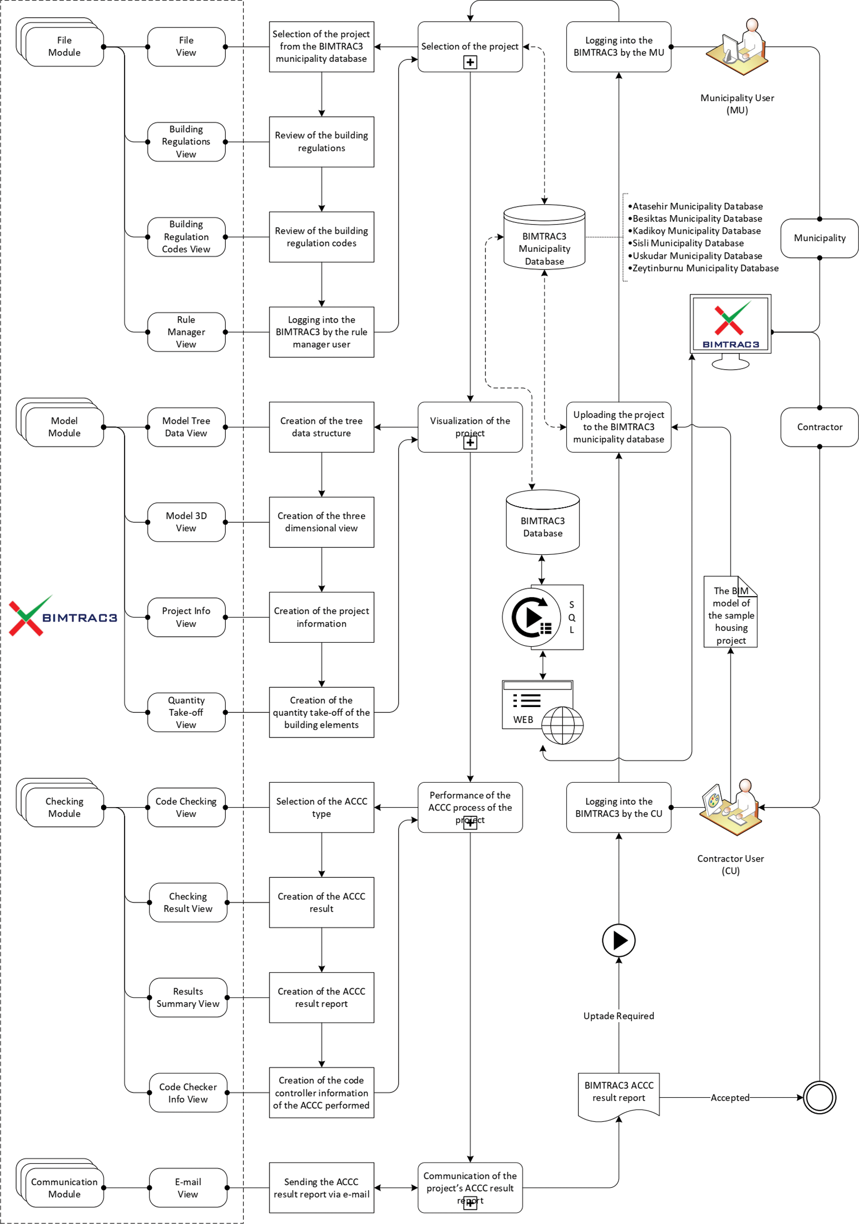
Figure 8: The implementation workflow chart of BIMTRAC3
A BIM-based BIMTRAC3 providing an automated code compliance checking process for housing projects in Turkey was established according to the Planned Areas Zoning Regulation for municipality users based on the literature review in the field of BIM and ACCC in the present study. The sample housing project was uploaded to the BIMTRAC3 municipality database with BIMTRAC3 and visualized. ACCC operations were performed, and the ACCC report was submitted. BIMTRAC3 provides various solutions for the problems encountered in ACCC when performed by municipalities. These are as follows:
• The ACCC is performed by the municipality automatically by using a computer through BIMTRAC3.
• The ACCC is performed based on the BIM model created with BIM-based software rather than on drawing papers of the housing project.
• BIMTRAC3 eliminates errors, time losses, and misconduct arising from the manual execution of ACCC by municipalities.
• BIMTRAC3 avoids inconsistency between regulation clauses, unnecessary operations, and procedures in ACCC.
• BIMTRAC3 prevents municipalities from approving inappropriate housing projects according to the results of ACCC, thus relieving the municipality user from a serious responsibility.
• BIMTRAC3 offers a reliable, protected, and easily accessible archiving system for building regulations.
Although BIMTRAC3 is designed as a rule-based software for performing ACCC for housing projects in Turkey according to the Planned Areas Zoning Regulation, it can be applied to other building regulations such those pertaining to car parking, elevators, shelters, and energy performance in buildings. Therefore, BIMTRAC3 is recommended for municipality users. However, it can be improved according to the expectations and requirements of other participants involved in the building production process such as architects, engineers, owners, employers, contractors, subcontractors, and construction managers. BIMTRAC3 will contribute to the economy of Turkey when it is released on the market as software with the financial and workforce support of individuals, institutions, or organizations.
Acknowledgement: This study was prepared as a part of the doctoral thesis titled” A BIM-Based Automated Building Regulation Compliance Checking Model for Residential Projects in Turkey, BIMTRAC3” within the scope of the Ph.D. Program in Construction Sciences of Istanbul Technical University, Graduate School of Science Engineering and Technology, Department of Architecture. Thesis advisor is Prof. Dr. Hakan Yaman. BIMTRAC3 software is protected by the Turkish Patent and Trademark Office. The patent number is 2019/86598.
Funding Statement: This study was funded by the Research Fund of the Istanbul Technical University. Project Number is MDK-2018-41197.
Conflicts of Interest: The authors declare that they have no conflicts of interest to report regarding the present study.
1. A. Alghamdi, M. Sulaiman, A. Alghamdi, M. Alhosan, M. Mastali et al. (2017). , “Building accessibility code compliance verification using game simulations in virtual reality,” in ASCE Int. Workshop on Computing in Civil Engineering 2017, Seattle, Washington, USA, pp. 262–270. [Google Scholar]
2. Ciribini A. L. C., Mastrolembo Ventura S. and Paneroni M. (2016). “Implementation of an interoperable process to optimise design and construction phases of a residential building: A bim pilot project,” Automation in Construction, vol. 71, no. 8, pp. 62–73. [Google Scholar]
3. C. Eastman, J. M. Lee, Y. S. Jeong and J. K. Lee. (2009). “Automatic rule-based checking of building designs,” Automation in Construction, vol. 18, no. 8, pp. 1011–1033. [Google Scholar]
4. L. Jiang and R. M. Leicht. (2015). “Automated rule-based constructability checking: Case study of formwork,” Journal of Management in Engineering, vol. 31, no. 1, pp. 1–10. [Google Scholar]
5. H. Lee, J. K. Lee, S. Park and I. Kim. (2016). “Translating building legislation into a computer-executable format for evaluating building permit requirements,” Automation in Construction, vol. 71, no. 2009, pp. 49–61. [Google Scholar]
6. Y. C. Lee, C. M. Eastman and J. K. Lee. (2015). “Automated rule-based checking for the validation of accessibility and visibility of a building information model,” in ASCE Int. Workshop on Computing in Civil Engineering 2015, Austin, Texas, USA, pp. 572–579. [Google Scholar]
7. H. Luo and P. Gong. (2015). “A bim-based code compliance checking process of deep foundation construction plans,” Journal of Intelligent and Robotic Systems: Theory and Applications, vol. 79, no. 3–4, pp. 549–576. [Google Scholar]
8. S. Malsane, J. Matthews, S. Lockley, P. E. D. Love and D. Greenwood. (2015). “Development of an object model for automated compliance checking,” Automation in Construction, vol. 49, no. 1, pp. 51–58. [Google Scholar]
9. J. P. Martins and A. Monteiro. (2013). “Lica: A bim based automated code-checking application for water distribution systems,” Automation in Construction, vol. 29, no. 23, pp. 12–23. [Google Scholar]
10. N. O. Nawari. (2011). “Automating codes conformance in structural domain,” Computing in Civil Engineering, vol. 18, no. 4, pp. 569–577. [Google Scholar]
11. N. O. Nawari. (2013). “Smartcodes and bim,” in Structures Congress, Pittsburgh, Pennsylvania, USA, pp. 928–937. [Google Scholar]
12. C. Preidel and A. Borrmann. (2017). “Refinement of the visual code checking language for an automated checking of building information models regarding applicable regulations,” in Computing in Civil Engineering 2017: Information Modeling and Data Analytics, Seattle, Washington, USA, pp. 157–165. [Google Scholar]
13. S. Y. Shih, W. Sher and H. Giggins. (2013). “Assessment of the building code of Australia to inform the development of bim-enabled code checking system,” in Proc. of the 19th World Building Congress: Construction and Society, Brisbane, Australia, pp. 1–12. [Google Scholar]
14. Q. Z. Yang and X. Xu. (2004). “Design knowledge modeling and software implementation for building code compliance checking,” Building and Environment, vol. 39, no. 6, pp. 689–698. [Google Scholar]
15. C. Zhang, J. Beetz and M. Weise. (2015). “Interoperable validation for IFC building models using open standards,” Journal of Information Technology in Construction, vol. 20, pp. 24–39. [Google Scholar]
16. J. Zhang and N. M. El-Gohary. (2017). “Integrating semantic NLP and logic reasoning into a unified system for fully-automated code checking,” Automation in Construction, vol. 73, no. 12, pp. 45–57. [Google Scholar]
17. J. Zhang and N. M. El-Gohary. (2016). “Extending building information models semiautomatically using semantic natural language processing techniques,” Journal of Computing in Civil Engineering, vol. 30, no. 5, pp. 1–16. [Google Scholar]
18. M. Aydın and H. Yaman. (2018). “An overview of building information modelling (bim) based building code compliance checking literature,” Journal of Design+Theory, vol. 14, no. 25, pp. 59–77. [Google Scholar]
19. M. Aydın and H. Yaman. (2020). “A literature review of automated code compliance checking concept,” Journal of Design+Theory, vol. 16, no. 29, pp. 79–97. [Google Scholar]
20. D. Greenwood, S. Lockley, S. Malsane and J. Matthews. (2010). “Automated compliance checking using building information models,” in Proc. of the Construction, Building and Real Estate Research Conf., Paris, France, pp. 363–371. [Google Scholar]
21. L. Ding, R. Drogemuller, M. Rosenman, D. Marchant and J. Gero. (2006). “Automating code checking for building designs—Designcheck,” in Clients Driving Innovation: Moving Ideas into Practice, Sydney, Australia, pp. 1–16. [Google Scholar]
22. M. Aydın and H. Yaman. (2020). “Domain knowledge representation languages and methods for building regulations,” in Advances in Building Information Modeling, vol. 1188. Cham, Switzerland: Springer International Publishing, pp. 101–121, . [Online]. Available: https://link.springer.com/chapter/10.1007/978-3-030-42852-5_9 [Google Scholar]
23. T. M. H. Reenskaug. (1979). “The original MVC reports,” [Online]. Available: https://www.duo.uio.no/bitstream/handle/10852/9621/Reenskaug-MVC.pdf?sequence=1&isAllowed=y [Google Scholar]
 | This work is licensed under a Creative Commons Attribution 4.0 International License, which permits unrestricted use, distribution, and reproduction in any medium, provided the original work is properly cited. |