DOI:10.32604/iasc.2021.017235
| Intelligent Automation & Soft Computing DOI:10.32604/iasc.2021.017235 | |
| Article |
Research on Tracking and Registration Algorithm Based on Natural Feature Point
1Shcool of Information and Intelligence Engineering University of Sanya, Sanya, China
2Engineering Technology and Applied Science, Centennial College, Toronto, Canada
*Corresponding Author: Tingting Yang. Email: ytt1202@126.com
Received: 24 January 2021; Accepted: 27 February 2021
Abstract: In the augmented reality system, the position and direction of the user’s point of view and line of sight in the real scene is acquired in real-time. The position and direction information will determine the exact position of the virtual object of the real scene. At the same time, various coordinate systems are established according to the user’s line of sight. So registration tracking technology is very important. The paper proposes an accurate, stable, and effective augmented reality registration algorithm. The method adopts the method of ORB (oriented FAST and rotated BRIEF) features matching combined with RANSAC (random sample consensus) to obtain the homography matrix and then uses the KLT (kanade-lucas-tomasi) tracking algorithm to track the mark, which is a better solution. The error accumulation defect based on the natural feature tracking registration method is improved, and the stability and accuracy of the registration are improved. Experiments have proved that the algorithm in this paper is accurate, stable, and effective, and can complete the virtual and real registration tasks accurately and stably even when the marked part is not visible.
Keywords: Augmented reality; natural feature points; registration algorithm
Augmented Reality (AR) can be defined as a system that fulfills three basic features: a combination of real and virtual worlds, real-time interaction, and accurate 3D registration of virtual and real objects [1]. AR is based on Virtual Reality (VR) technology developed. Virtual reality is a combination of multimedia technology and simulation technology to generate a realistic vision, in a virtual environment that integrates hearing and touch, users experience and interact with objects in the virtual environment in a natural way function to produce immersive feelings and experiences. It is the use of objectively existing or non-existent things computer technology, a technology that creates a virtual environment in front of the user's eyes and makes people feel immersed in the virtual environment. While, augmented reality is processed by computer technology, tracking the user’s position in the real scene, and combining computer-generated virtual information overlay applies to the real world, and using sensor technology and display equipment to unify the virtual information and the real world in the screen or space [2]. The entity information that is difficult to experience in a certain time and space in the actual world is superimposed and enhanced to be perceived by the human senses in the real world, to achieve beyond reality sensory experience, creating an unimaginable feeling for users.
The concept of AR is defined by Professor Ronald T. Azuma in [3] in 1997. It mainly includes three aspects: combines real and virtual things, interactive in real time, registered in 3-D. Because of the high computational complexity of the unmarked 3D registration algorithm in the augmented reality system, affect the real-time performance and the problem of feature point detection failure when motion blur occurs. This paper proposes a vision-based unmarked 3D registration method.
The structure of the paper is as follows: Section 2 shows the 3D registration methods of augmented reality. Among these algorithms, unmarked registration has gradually become a new hot spot in the research of the augmented reality system. Therefore, by comparing the three methods of natural feature point registration, SIFT (scale-invariant feature transform), SURF (speeded up robust features), and ORB (oriented FAST and rotated BRIEF), the paper proposes the improvement and application of ORB algorithm. In Section 3, we mainly describe the transformation principle of the coordinate system in the enhancement implementation; in Section 4, we propose our own improvement method by describing the problems existing in the traditional ORB algorithm and use the KLT (Kanade-Lucas-Tomasi) tracking algorithm to track the mark. Finally, the analysis of experimental results and conclusions are discussed in Section 5 and Section 6.
The paper proposes an accurate, stable, and effective augmented reality registration algorithm. The method adopts the method of ORB feature matching combined with RANSAC to get the homography matrix and then uses the KLT tracking algorithm to track the mark, which is a better solution the error accumulation defect based on the natural feature tracking registration method is improved, and the stability and accuracy of the registration are improved. Experiments have proved that the algorithm in this paper is accurate, stable, and effective, and can complete the virtual and real registration tasks accurately and stably even when the marked part is not visible.
To achieve accurate three-dimensional registration for tracking and registration in the augmented reality system, the position of the camera in the real scene must be obtained in real-time, the position and direction information of the user’s point of view, to use the conversion relationship between the coordinate systems according to the position information of the camera. The superimposed virtual objects are correctly projected to the exact position of the real scene. Obviously, the registration part is a necessary prerequisite for seamless integration between the real scene and the virtual scene. If there is a slight error in the 3D registration module, the registration result of the augmented reality system will be wrong, which will cause the fusion between the real scene and the virtual object to fail [4]. This kind of error 3D registration result not only cannot enhance the user's perception of the real world but will confuse users. Therefore, to achieve a natural three-dimensional registration effect consistent with reality, the high-precision and robustness requirements of three-dimensional registration must be met. The marker-based registration method represented by ARToolkit must place easily identifiable markers in the scene in advance, and at the same time, the markers must not be blocked, otherwise, the registration will fail. The marker-less registration method replaces specific markers by detecting natural feature points, which extends the application scope of AR [5]. As the three-dimensional registration method based on markers cannot meet the increasing demand for augmented reality applications, people focused on the unmarked registration method. Unmarked registration has gradually become a new hot spot in the research of augmented reality systems [6].
In the field of computer vision, the feature point refers to the point where the gray value of the image changes drastically or a point with a larger curvature on the edge of the image. The feature point is composed of two parts: a key point and a descriptor. The key point refers to the specific position of the feature point in the image [7]. The descriptors are used to show the information of the pixels around the key point and are the identity information of the feature point, and compare the similarity between different feature points.
There are three feature points based on natural feature points registration are SIFT(Scale-Invariant Feature Transform) , SURF(Speeded Up Robust Features),and ORB(Oriented FAST and Rotated BRIEF). SIFT features have many advantages such as rotation, scale, and illumination in-variance, and each feature points are highly unique, but an enormous amount of calculation. The SURF feature uses the Hessian matrix for feature extraction. Compared with the SIFT feature, SURF features have a significant advantage in extraction speed. The ORB feature is implemented based on the FAST feature points and the binary descriptor BRIEF. The ORB feature extraction speed is extremely fast, and it has rotation and scale in-variance. Since the extraction and matching of feature points are only a small part of the many links in the system, for systems with high real-time requirements, ORB features are usually selected. KLT is a feature point tracking algorithm based on the principle of optical flow. The KLT algorithm is essentially based on the three assumptions of the optical flow principle. Unlike the optical flow algorithm that directly compares the gray values of pixels; the KLT algorithm compares the window pixels around the pixel to find the most similar pixel.
This paper uses the ORB (oriented FAST and rotated BRIEF) feature matched algorithm combined with the random sampling consistency (RANSAC) method to get the homography matrix to complete the virtual and real registration, to find the three-dimensional information of a real scene image, and then use the KLT tracking algorithm to track the mark.
3 Principles of Augmented Reality 3D Registration
AR needs to consider multiple transformation systems, see Fig. 1 [3]. The perspective transformation describes the mapping from eye coordinates to screen coordinates. The model transformation describes the pose of moving objects in a static environment. To achieve the effect of virtual and real fusion, first, need to obtain the registration information corresponding to the current image, and then calculate The virtual object generated by the machine performs projection transformation according to the registration information, and then superimposes the transformation result on the real scene, thus To achieve positional consistency with real objects in the perspective relationship, this is also the main task of 3D registration technology.
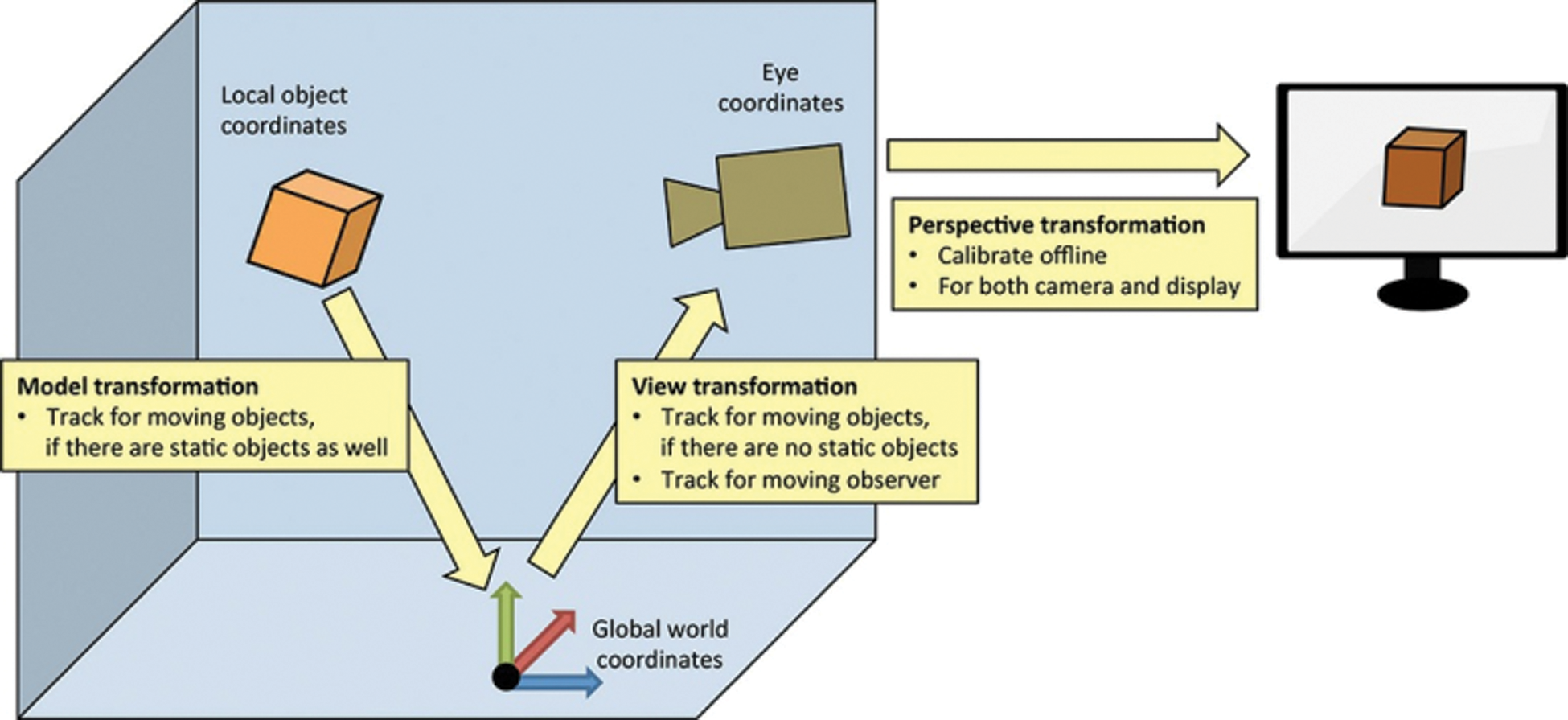
Figure 1: Augmented reality coordinate system (multiple transformation systems of model transformation, the view transformation, the perspective transformation)
The Cartesian coordinate system is used mainly for its simplicity and familiarity and most virtual spaces are defined by it. The x-y-z based coordinate system is precise for specifying the location of 3D objects in virtual space. The three coordinate planes are perpendicular to each other. Distances and locations are specified from the point of origin which is the point where the three planes intersect with each other. This system is mainly used for defining visual coordinates of 3D objects.
3.1.2 The Pixels of the Image Coordinate System Coordinates
The image collected by the camera is converted into a digital image by a high-speed image acquisition system in the form of a standard TV signal and then input into the computer. Each image is an M*N array and the value of each element in the image of M rows and N columns is the brightness of the image point, and (u, v) are the pixels of the image coordinate system coordinates.
Since (u, v) only represents the number of columns and rows of the pixel in the array, the position of the pixel in the image is not expressed in physical units. Therefore, it is necessary to establish an image coordinate system expressed in physical units, that is, the XOY coordinate system shown in the Fig. 2. In the X.Y coordinate system, the origin O is usually defined as the intersection of the camera’s optical axis and the image plane. This point is located at the center of the image, but sometimes it may deviate. The transformation from the two-dimensional camera coordinate system to the image coordinate system can be described by the following matrix:
Then (u0, v0) are the coordinates of the origin of the image coordinate system in the pixel coordinate system, dx and dy are the physical dimensions of each pixel in the x and y directions of the image plane.
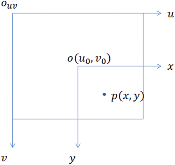
Figure 2: The relationship chat of image coordinate ad pixel coordinate
As shown in Fig. 3, point O is called the optical center of the camera, the x-axis and y-axis are parallel to the X-axis and Y-axis of the image, and the z-axis is the camera optical axis, which is perpendicular to the image plane. The focal point of the optical axis and the image plane is the origin of the image coordinate system, and the rectangular coordinate system formed by the point O and the x, y, and z axes is called the camera coordinate system, and OO1 is the focal length of the camera. The transformation from the camera coordinate system to the world coordinate system is a 3D-3D transformation process, and their relationship can be perfectly described by the rotation matrix R and the translation vector t. That is, the relationship is as follows:
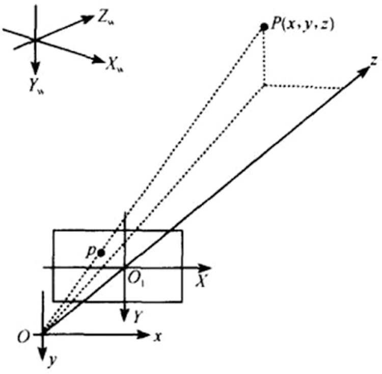
Figure 3: The relationship chat of camera coordinate and image coordinate
3.1.5 Virtual Coordinate System
The virtual coordinate system is a geometric description of virtual objects. When using an augmented reality system, the virtual coordinate system coincides with the world coordinate system or is proportional to each other. The transformation relationship between them is as follows:
For any point P, the intersection of the image plane and O is the projection position of point P on the image. This kind of projection relationship is also called central projection or perspective projection. Assuming p point is in the imaging plane coordinates The coordinates of the system are (x, y), and the coordinates in the camera coordinate system are (Xc, Yc, Zc, 1), the perspective projection relationship can be described in homogeneous coordinates and matrix form:
According to formulas (1) and (2), the relationship between the coordinates of point p and the corresponding projection coordinates (u, v) of point p can be obtained, as shown in formula (5):
M is the projection matrix; M1 is determined by four parameters bx, by, u0, v0, among which the parameters are only related to the internal parameters of the camera, so we define it as the internal parameters of the camera. M2 is affected by the camera relative to the world coordinate system and is called the external parameters of the camera. Therefore, determining the internal and external parameters of a certain camera is called camera calibration.
3.3 Principles of Augmented Reality 3D Registration
Registration technology enables virtual images to be superimposed accurately in the proper environment. The main flow of 3d registration technology has two steps. First, determine the relationship between the virtual image, the model and the direction and position information of the camera or display device. Second, the virtual rendered image and model are accurately projected into the real environment, so the virtual image and model can be merged with the real environment. For the three-dimensional registration technology based on computer vision, it sets the reference point to realize the determination of the direction and position of the real scene by the camera or the display.
To realize the three-dimensional registration process in augmented reality, the internal and external parameters of the camera are required. In fact, the camera calibration determines the internal parameter matrix (5), and the external parameter matrix M contains a translation component T and 3 rotation components. Therefore, the external parameter matrix M of each frame of the image obtained in the three-dimensional registration can be uniquely determined
The position of the point, that is, the accurate registration position of the virtual object in the real scene.
4 Improved Image Registration Method
Due to the use of special manual marking, there are some limitations. This paper uses the ORB (oriented FAST and rotated BRIEF) feature matching algorithm combined with the random sampling consistency (RANSAC) method to obtain the homography matrix to complete the virtual and real registration, that is, to find the three-dimensional information of a real scene image, and then use the KLT tracking algorithm to track the mark. Experiments show that the tracking and registration algorithm based on natural feature points can accurately identify natural objects and have a certain resistance to occlusion.
ORB (Oriented FAST and Rotated BRIEF) was developed at OpenCV labs by Ethan Rublee, Vincent Rabaud, Kurt Konolige, and Gary R. Bradski in 2011, as an efficient and viable alternative to SIFT and SURF. ORB was conceived mainly because SIFT and SURF are patented algorithms. However, ORB is free to use. ORB performs and SIFT on the task of feature detection (and is better than SURF) while being almost two orders of magnitude faster. ORB builds on the well-known FAST key points detector and the BRIEF descriptor. All of these techniques are attractive because of their excellent performance and low cost [8].
The ORB algorithm is based on the FAST algorithm for feature point detection [9]. Compared with the SIFT algorithm and the SURF algorithm, the calculation performance is greatly improved. The FAST algorithm detects the image feature point by comparing the light and dark information of the center pixel and the surrounding pixels. However, the characteristic points obtained by FAST detection do not perform well in terms of scale characteristics and rotation in-variance [10]. If it is satisfied: in the field of a certain point p, there is enough gray value greater than or less than the gray value of the point, then point p is a characteristic point. The corner point response function can be expressed as Eq. (6):
So x is the pixel in point p, I(x) and I (p) are the gray points of point p and point x in the target image; and where ɛd is the given threshold; then the preset threshold is less than the number of all pixels that meet the above formula N, So this point is corner point.
To obtain the rotational invariant feature, the first moment is used to calculate the local direction through the weighted average of the pixel size in the local region. The moment definition of image block in the literature is given as equation.
We can describe the basic idea of BRIEF feature description as Eq. (8):
Randomly select n pixel pairs in the neighborhood of a feature point, and calculate the gray value of all point pairs according to the binary rule. Then generate a binary string of length n, which is the feature descriptor of the feature point. Once the ORB feature detection algorithm is derived [11], the feature descriptor can be calculated by using the feature point with scale characteristics. The feature description of the ORB algorithm is based on the feature description of the BRIEF algorithm, which gives the rotation in-variance by the Steered BRIEF method and trains the test results through the greedy search method, then uses the statistical learning method to re-select the point-to-point set. As a result, the ORB algorithm has achieved better diversity and lower correlation [12].
The binary criterion can be effectively defined by selecting nd (x,y) position pairs, and the binary bit string of dimension is the BRIEF descriptor,
Optical Flow is the projection of the motion of an object in a three-dimensional space on a two-dimensional image plane. It is generated by the relative speed of the object and the camera and reflects the direction and speed of the image pixel corresponding to the object in a tiny time. KLT (Kanade-Lucas-Tomasi) is a feature point tracking algorithm based on the principle of optical flow [13].
The KLT algorithm is essentially based on the three assumptions of the optical flow principle. Unlike the optical flow algorithm that directly compares the gray values of pixels; the KLT algorithm compares the window pixels around the pixel to find the most similar pixel. Based on the optical flow assumption, in a short time τ, the two images before and after meeting:
The pixel displacement vector satisfies the affine motion model D = Dx + d; among them, D is called Deformation Matrix, and d is called Displacement Vector. D represents the deformation of the two pixel window blocks after the movement, so when the window is small, it will be more difficult to estimate. Usually D can measure the similarity of two pixel windows, that is, to measure whether the feature points have drifted. For the amount of optical flow tracking only the translation model is considered:
Under the pixel window, construct the error function:
Where w(x) is the weight function, which can be defined as Gaussian. The above equation takes the derivative of the variables D and d respectively:
Given the translational motion model result, let D = 0:
However, the KLT algorithm cannot maintain the number of feature points, so the number of feature points will gradually decrease, and the reduction of feature points will affect the accuracy of the homography matrix solution [14]. By judging the number of feature points, when the number of feature points is lower than a certain threshold, the KLT feature points are updated.
4.3 Marker-less Registration Algorithm Based on ORB and KLT
In this paper, the homography matrix can be obtained by using ORB feature matching combined with random sampling consistency, and then the KLT tracking algorithm is used to track the markers. Through the previous (1), (2), and (3), the homography matrix s value can be obtained by an iterative method. With the initial frame, it can be obtained by the method of ORB feature matching combined with RANSAC [15–17]. Here, assuming that s is known, define the matrix sm+1 as the homography matrix between the image plane of the i+1 frame and the image plane of the i+1 frame:
Therefore, the camera pose M can be calculated to complete the virtual and real registration.
5 Experimental Results and Analysis
This experiment runs on the system of windows 10, VS 2015, OpenCV 3.2.1 and OpenGL are used to implement image registration methods based on improved ORB and RANSAC. In the experiment, the hardware configuration included Intel Core i7-7700K CPU 3.60GHz, 8G memory, and microsoftHD-3000 camera.
In the Figs. 4a, 4b and 4c result from tracking registration under partially occluded and unoccluded, different light and viewing angle changes. The system can accurately complete the registration task even when the identification part is not visible, and successfully add the virtual cube in the real scene.
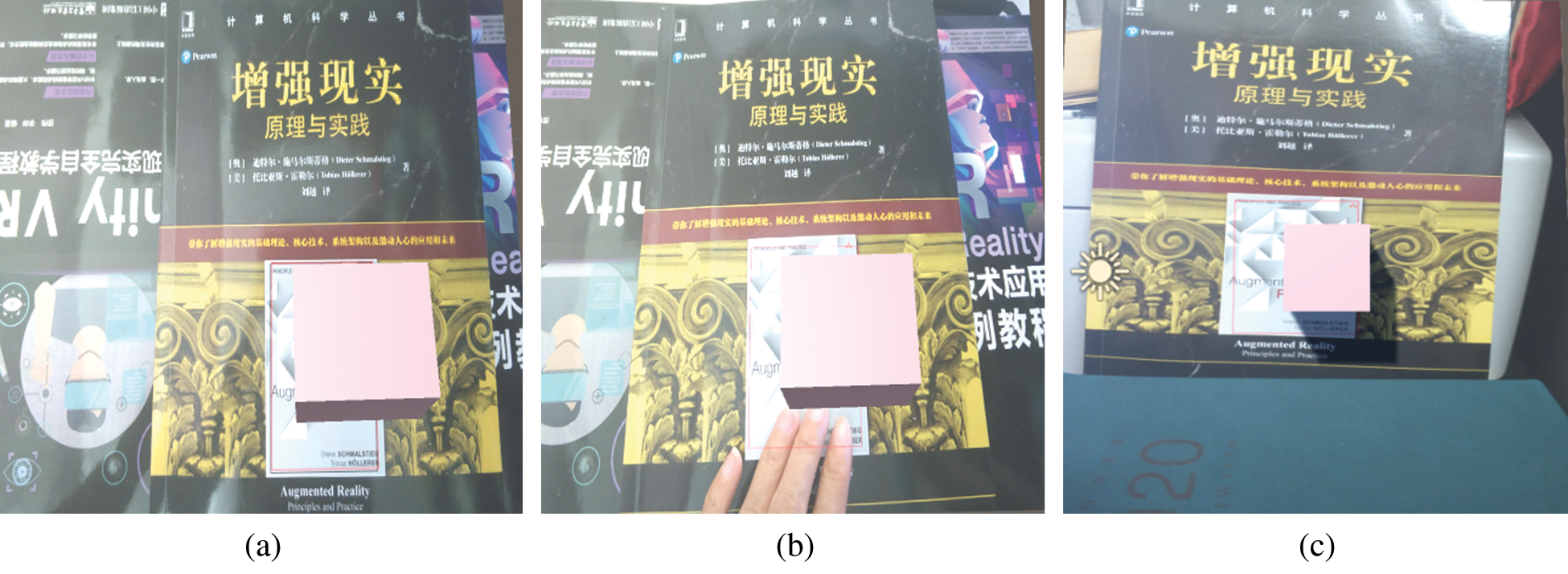
Figure 4: The results of tracking registration under partially occluded and unoccluded (a) Target working scene with no occlusion (b) Working scene with partial occlusion (c) working scene with different perspectives
Through experiments, it is found that the algorithm in this paper can accurately track and register flat natural objects. From Fig. 4b, it can be seen that when the natural feature points are partially occluded, the system can find the target and successfully add the cube to the natural object; Fig. 4c are screen-shots of the experimental results under different viewing angles and lighting conditions. Due to the reduction of feature points caused by the KLT tracking method, this paper determines that when the natural feature points are reduced to 18, the ORB algorithm is immediately used for correction to ensure accuracy. The feature tracking algorithm based on KLT is used for the same video respectively. The tracking registration method proposed in this paper is compared and found that by detecting the rotation components (R1, R2, R3), it is found that when the number of frames reaches about 1000 frames, the KLT method is used. The errors of R1 and R2 are both over 10 degrees and our method can guarantee it within 3 degrees.
Aiming at the defects of low registration rate and high error rate of traditional ORB algorithm, this paper proposes an improved AR image registration method based on ORB algorithm and RANSAC, to obtain the homography matrix to complete the virtual and real registration, that is, to find the three-dimensional information of a real scene image, and then use the KLT tracking algorithm to track the mark. Experiments show that the tracking and registration algorithm based on natural feature points can accurately identify natural objects and have a certain resistance to occlusion. In future work, we will further optimize the algorithm of this paper to satisfy the actual requirements of various environments. Besides, research on camera pose calculation will be continued to further enhance the scene’s effect.
Funding Statement: The authors received no specific funding for this study.
Conflicts of Interest: The authors declare that they have no conflicts of interest to report regarding the present study.
1. H. K. Wu, S. W. Lee, H. Y. Chang and J. C. Liang, “Current status, opportunities and challenges of augmented reality in education,” Computers & Education, vol. 62, no. 3, pp. 41–49, 2013. [Google Scholar]
2. D. Schmalstieg and T. Höllerer, “Tracking,” in Augmented Reality Principles and Practice, 1st edition, Boston, USA: Addison-Wesley Press, pp.140–145, 2016. [Google Scholar]
3. R. T. Azuma, “A survey of augmented reality,” Presence: Teleoperators and Virtual Environments, vol. 6, no. 4, pp. 355–385, 1997. [Google Scholar]
4. J. Carmigniani, B. Furht, M. Anisetti, P. Ceravolo, E. Damini et al., “Augmented reality technologies, systems and applications,” Multimedia Tools and Applications, vol. 51, no. 1, pp. 341–377, 2011. [Google Scholar]
5. Y. Wang, S. Zhang, S. Yang, W. He and X. Bai, “Mechanical assembly assistance using marker-less augmented reality system,” Assembly Automation, vol. 38, no. 1, pp. 77– 87, 2018. [Google Scholar]
6. B. P. Zhang, “Design of mobile augmented reality game based on image recognition,” Eurasip Journal on Image and Video Processing, vol. 2017, no. 1, pp. 1–20, 2017. [Google Scholar]
7. S. Y. Moon, S. Y. Yun, H. S. Kim and L. S. Kang, “Improved method for increasing maintenance efficiency of construction structure using augmented reality by marker- less method,” Journal of The Korean Society of Civil Engineers, vol. 35, no. 4, pp. 961– 968, 2015. [Google Scholar]
8. M. Z. Cheng, L. Y. Zhang and L. Liu, “An augmented reality image registration method based on improved ORB,” Journal of Physics: Conf. Series, vol. 1554, no. 1, pp. 1– 10, 2020. [Google Scholar]
9. M. L. Wu, J. C. Chien, C. T. Wu and J. D. Lee, “An augmented reality system using improved-iterative closest point algorithm for on-patient medical image visualization,” Sensors, vol. 18, no. 8, pp. 2505–2520, 2018. [Google Scholar]
10. M. Zhang, K. Zeng and J. Wang, “A survey on face anti-spoofing algorithms,” Journal of Information Hiding and Privacy Protection, vol. 2, no. 1, pp. 21–34, 2020. [Google Scholar]
11. A. Takacs, M. T. oledano Ayala, J. C. Pedraza-Ortega and E. A. Rivas-Araiza, “Dedicated feature descriptor for outdoor augmented reality detection,” Pattern Analysis and Applications, vol. 21, no. 2, pp. 351–362, 2018. [Google Scholar]
12. P. P. Cacciari and M. M. Futai, “Modeling a shallow rock tunnel using terrestrial laser scanning and discrete fracture network,” Rock Mechanics and Rock Engineering, vol. 50, no. 5, pp. 1217–1242, 2017. [Google Scholar]
13. M. S. Sri, “Object detection and tracking using KLT algorithm,” International Journal of Engineering Development Research, vol. 7, no. 2, pp. 542–545, 2019. [Google Scholar]
14. H. Liu and X. Zhou, “Multi-focus image region fusion and registration algorithm with multi-scale wavelet,” Intelligent Automation & Soft Computing, vol. 26, no. 4, pp. 1493–1501, 2020. [Google Scholar]
15. A. Y. Hamed, M. H. Alkinani and M. R. Hassan, “A genetic algorithm optimization for multi-objective multicast routing,” Intelligent Automation & Soft Computing, vol. 26, no. 4, pp. 1201–1216, 2020. [Google Scholar]
16. C. Cheng and D. Lin, “Image reconstruction based on compressed sensing measurement matrix optimization method,” Journal on Internet of Things, vol. 2, no. 1, pp. 47–54, 2020. [Google Scholar]
17. G. Ravikanth, K. V. N. Sunitha and B. E. Reddy, “Location related signals with satellite image fusion method using visual image integration method,” Computer Systems Science and Engineering, vol. 35, no. 5, pp. 385–393, 2020. [Google Scholar]
 | This work is licensed under a Creative Commons Attribution 4.0 International License, which permits unrestricted use, distribution, and reproduction in any medium, provided the original work is properly cited. |