DOI:10.32604/iasc.2021.017534
| Intelligent Automation & Soft Computing DOI:10.32604/iasc.2021.017534 | |
| Article |
Self-Regulated Single-phase Induction Generator for Variable Speed Stand-alone WECS
1Department of Electrical and Electronics Engineering technology, Yanbu Industrial College (YIC), Yanbu, KSA
2Electrical Engineering Department, College of Engineering, Taif University, Taif, 21944, Saudi Arabia
3Department of Engineering Physics and Mathematics, Faculty of Engineering, Zagazig University, Zagazig, Egypt
4Department of Electrical Engineering Faculty of Technology and Education, Beni-Suef University, Beni-Suef, Egypt
*Corresponding Author: Mohamed I. Mosaad. Email: m_i_mosaad@hotmail.com
Received: 29 January 2021; Accepted: 02 March 2021
Abstract: This paper introduces voltage self-regulation of a variable speed single-phase induction generator-based wind energy conversion system (WECS) for stand-alone applications. The idea behind the voltage self-regulation technique proposed in this paper is adjusting the fixed capacitor’s effective value for exciting the single-phase induction generator. This adjustment is performed using an inexpensive Sinusoidal PWM (SPWM) switching circuit to short circuit the capacitor during different periods to make a virtual change of the capacitance value extracted from the fixed capacitor. That optimized fixed capacitor size is firstly determined using harmony search (HS) optimization technique. HS is also used to determine the capacitance value required for voltage self-regulation of single-phase induction generators at different speeds through an optimal PI controller. To test the proposed system’s capability, different changes in the prime mover speed are applied to the rotor of the generator and the system succeeds at regulating the voltage with these speed variations. Moreover, a reduction in the harmonics in the output voltage was attained. The performance is of the HS optimization technique is compare to another optimization technique, particle swarm optimization.
Keywords: Self-excited induction generator; harmony search optimization; single-phase induction generator
Nomenclature
| Vload: | load voltage (generator voltage) |
| Vref : | reference voltage |
| VD, VQ: | d and q axis stator voltages respectively. |
| ID, IQ: | d and q axis stator currents respectively. |
| Id, Iq: | d and q axis rotor currents respectively. |
| RD, RQ: | d and q axis stator resistances respectively. |
| Rd, Rq: | d and q axis rotor resistances respectively. |
| LD, LQ: | d and q axis stator inductances respectively. |
| Ld, Lq: | d and q axis rotor inductances respectively. |
| MD, MQ: | d and q axis mutual inductances respectively. |
| Nd, Nq: | d and q axis number of turns respectively. |
| ωr: | rotor angular speed. |
| P: | derivative operation d/dt. |
Sustainable energy has recently played an important role in generating electric power due to its significant environmental, technical, and economic advantages. These advantages, clean fuel sources, do not produce atmospheric emissions, increase the number of jobs, open the door for the local investment in electric energy generation, increase the power system stability and reliability, and reduce the generating cost [1,2]. There are different types of sustainable sources like PV, wind, Fuel cell, and biomass [3].
Wind energy conversion systems (WECS) have received numerous and enormous uses to generate electric power. These usages are due to fuel depletion, pollution problems as well as modern trends relying on renewable energy generation. Wind energy is one of the most promising sources of renewable energy [2–7].
There are many types of generators used in wind energy systems. Not long ago, many current wind generators are Self Excited Induction Generators (SEIG) [8], Double Fed Induction Generators (DFIG) [9] and Switched Reluctance Generators (SRG) [10,11]. Most of the wind turbines installed right now uses SEIG (squirrel cage), DFIG (wound rotor), or direct-drive synchronous generators. SEIGs are widely used in wind turbine systems as they have many advantages, such as a wide range of speed, brushless structure, ruggedness, little maintenance, and low cost [4–8].
The large-scaled WECS based SEIG is extremely used in the generating level for large scales of MW. Such systems’ upcoming usage will be on the small scale of kilowatt (kW) or fractional kW, especially for the single-phase induction generators (SPIG). SPIGs are used in micro-hydro and wind energy generation plants in rural areas where the main rid is not available. They can be used either as on or off grid-connected [12,13]. In rural areas, where the population is little compared to other regions, the single-phase supply is more suitable than the three-phase supply.
Most of the single-phase induction generators are originally three-phase generators with some modifications in the phase connections. Connecting two phases in series and the third one to a capacitor is one of the well-known configuration methods for converting the three-phase induction machine into a single-phase one. Other configurations for that conversion are introduced in Bhattacharya et al. [14,15]. This conversion is due to complexity in modeling, analysis as well as structure. As a result, minimal literature review about using the single-phase induction machine in its structure on converting three-phase generators into single-phase one.
For SPIG types, there should be a reactive power compensation to fulfill both the reactive power demand for the turbine generators and the load’s reactive power [16]. That leads to poor voltage regulation of such generators if the reactive power is not well regulated. Capacitors are used as the sources of reactive power for the SPIG. The capacitance value hardly affects the voltage profile generated from SPIG, especially in the variable speed wind applications.
Different capacitances and different configurations are used to provide voltage support for SPIG. Three capacitors, one in parallel and two in series with the load, are used to provide the voltage support for SEIG types supply single-phase load. The control configuration of integrating those capacitances requires complex and accurate control methods, as in [17].
Many articles introduced some control methods to adjust the capacitance used for voltage support of the SPIG. Most of these control methods are mainly depends on the short circuit the capacitance for some intervals to change the effective value of that capacitance. This short circuit, electronic switch based, has three configurations: delay angle control, PWM and Sinusoidal PWM (SPWM). The best performance for the voltage profile as well as minimum harmonics is attained when using SPWM, [18–21].
In this paper, voltage self-regulated of SPIG based wind energy conversion system for isolated load using an inexpensive control circuit is introduced. This regulation is mainly based on introducing one capacitor to the auxiliary winding of the generator. The optimal capacitance of that capacitor used to excite and provide the voltage support of SPIG is calculated using harmony search (HR) optimization algorithm at the lowest wind speed. Then at different wind speeds, the effective capacitance is changed to keep the generator output voltage at 1 p.u irrespective of the wind speed variations.
The system proposed in this study is illustrated in Fig. 1. It is composed of a wind turbine system connected to the rotor of the single-phase induction generator. The main winding of the generator is connected to the load, while the auxiliary winding is connected to a controlled fixed capacitor. The control circuit proposed in this work is utilized to short circuit the capacitor during different time intervals at each cycle according to the generator’s output voltage. In other words, the control circuit is used to change the effective value of the fixed capacitor in order to regulate the terminal voltage of the generator under different operating wind speeds. The ratings of the single-phase induction machine is 0.4 kW and 170 V, [20].
3 Controller Design and Optimization Techniques
The capacitance value and consequently, the injected reactive power to the generator barely affect the terminal generated voltage. In order to regulate the voltage, a source of the reactive power (capacitor) should be varied or controlled. This work proposed a simple method for controlling the reactive power exploiting a fixed capacitor, Fig. 1. As shown in Fig. 1 the modulated switch/resistance branch is parallel to both L and C branches in the auxiliary winding. Therefore, that branch’s primary function is to dissipate the capacitor energy through the resistance based on the PWM technique, not bypassing the capacitor. Therefore, in turn, the voltage across these parallel combinations is reduced, so the excitation current in the auxiliary winding is controlled.
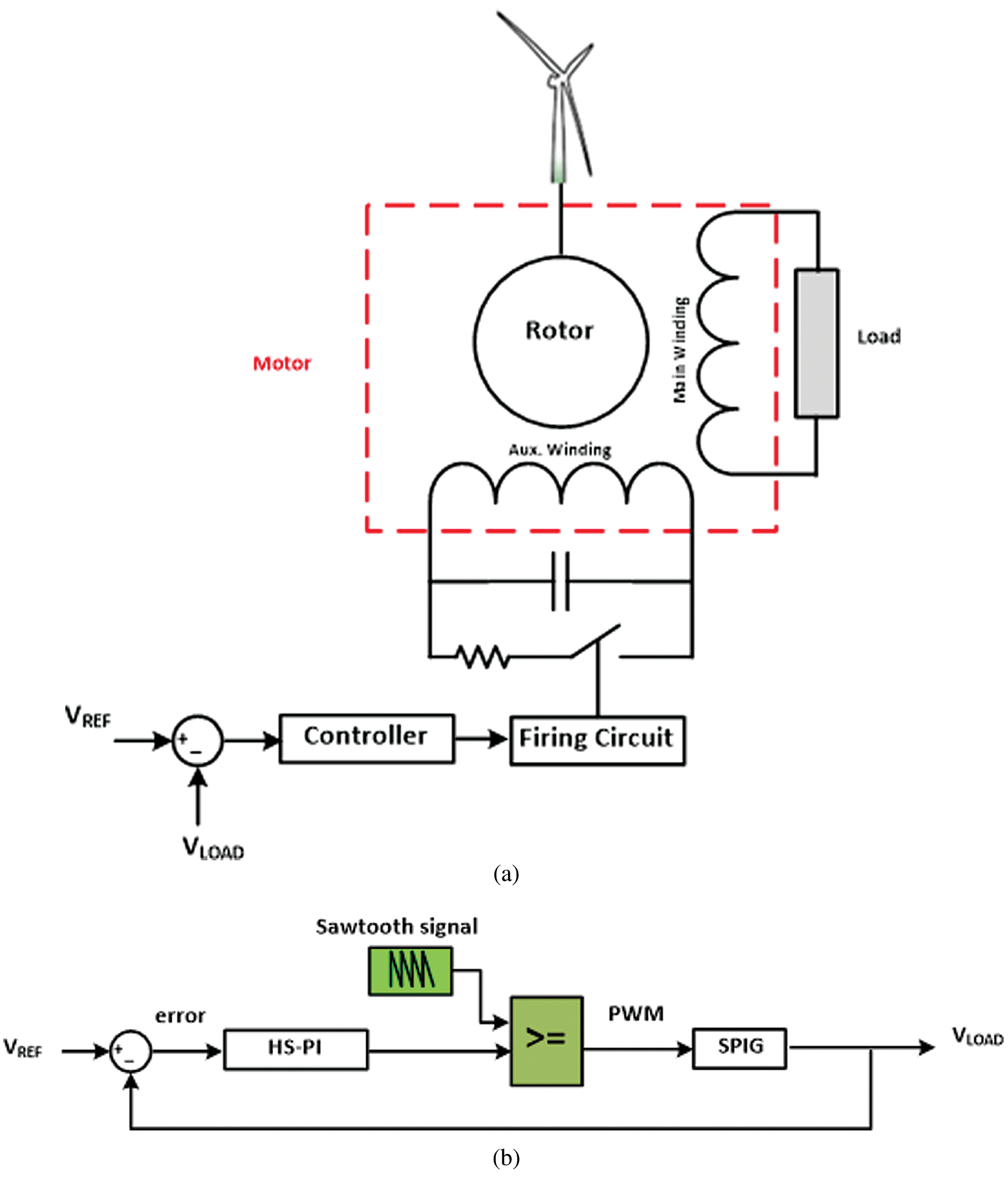
Figure 1: System under study (a) System description (b) Control block diagram
The difference between the generated (load) voltage and a reference voltage is updated and the error between these two values is used to stimulate a simple electronic circuit to bypass the capacitor for specific time intervals in each cycle to change the effective value of the capacitance of that fixed capacitor.
The first step is calculating the value of the fixed capacitor for the generator used in this work. The value of that capacitor is calculated using HS optimization technique.
The generated voltage level mainly depends on the wind speed driving the rotor of the SPIG. The HS is introduced to find the optimal capacitance required for voltage support at each speed.
3.1 Particle Swarm Optimization
To test the effectiveness the presented HS optimization technique in calculating the minimum capacitance required for exciting SPIG through generating a suitable PWM drive by PI controller, particle swarm optimization (PSO) is introduced. PSO is utilized in many optimization algorithms and could be considered as the benchmark for other optimization techniques [21,22]. PSO flow chart is shown in Fig. 2.
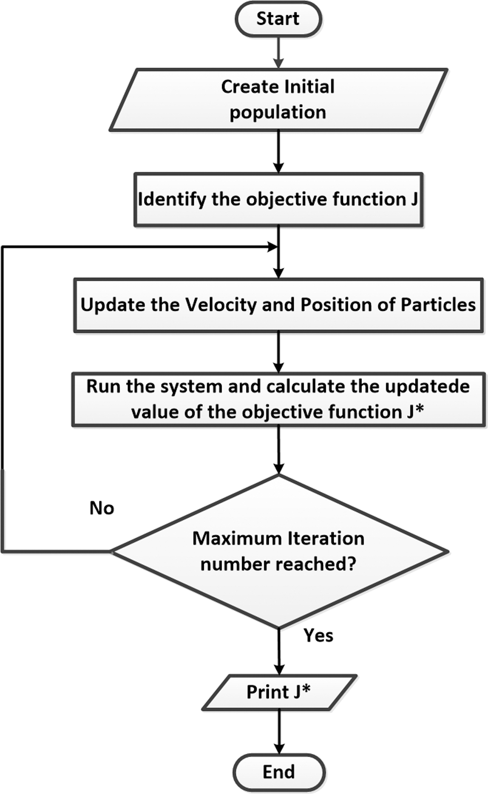
Figure 2: Flow chart of PSO
Many optimization techniques were presented in many power system applications [23,24]. The management of music is a process of finding or keeping better harmony by making various groupings of pitches following one of the following rules [24]:
1. Playing any one pitch from memory;
2. Playing a neighboring pitch of one pitch from memory;
3. Playing a random pitch from the possible range.
The flow chart for HS is given in Fig. 3.
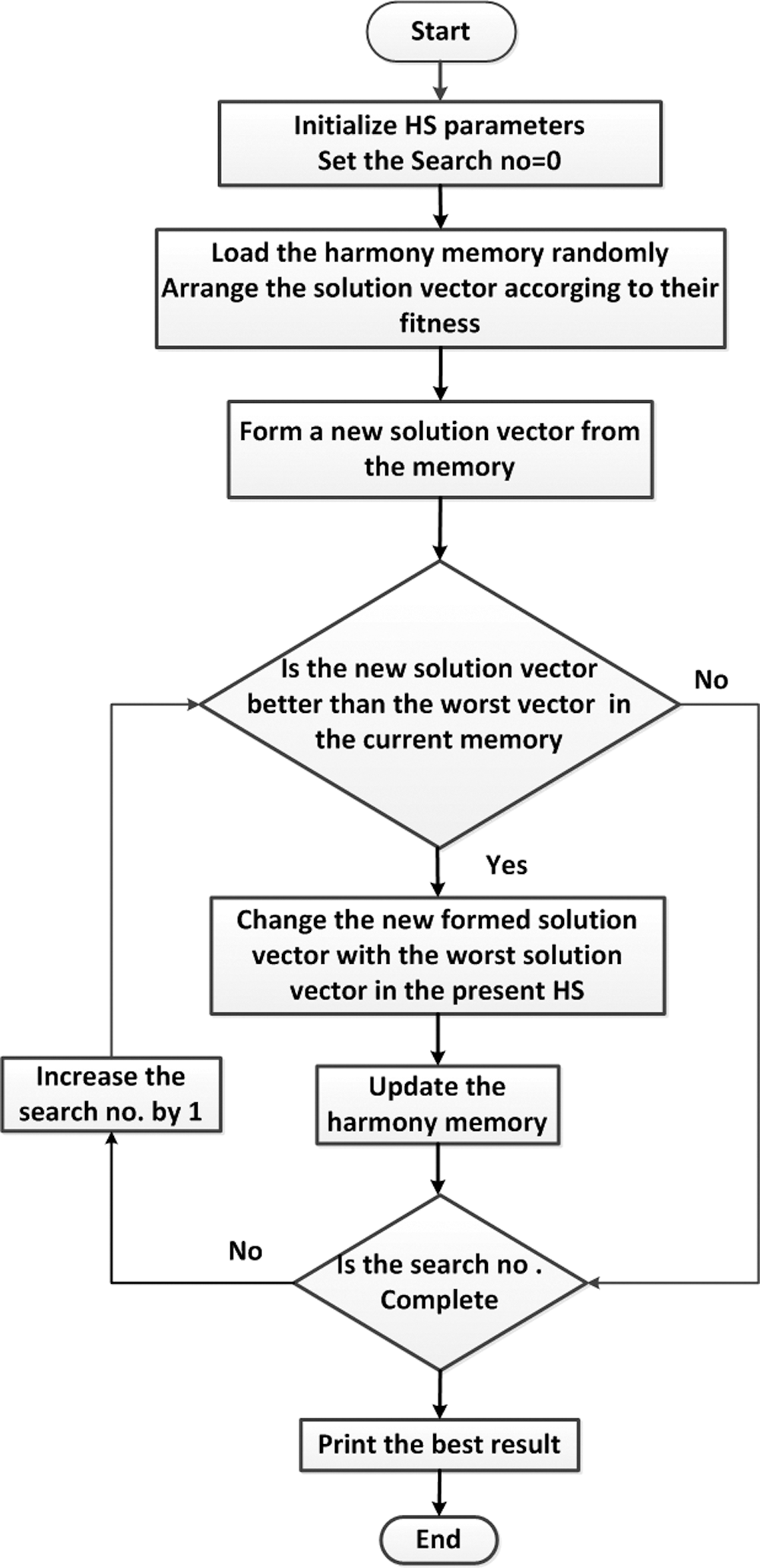
Figure 3: Flow chart of HS
The HS is used to find the minimum capacitance value of the fixed capacitor used for voltage self-regulation of the generator at the minimum allowable wind speed.
The objective for this optimization process is to minimize the Integral of Square of Error (ISE) between the load voltage (generator voltage), and a reference voltage as given in (1).
The cost function, J, is given by:
where J is the objective function.
The HS for this optimization problem is done depending on the following five operators:
1. Random playing. In which a random playable range of the capacitance values is proposed.
2. Memory considering. By the random proposed values in the random playing process, the objective function given in (1) is calculated. The preferred one (preferred note) is then selected with these new values rather than those specified in the first step. Storing these values in the form of a matrix is called Harmony Memory or Harmony Matrix (HM).
3. Pitch adjusting. The preferred ones’ neighborhood values are calculated to such that all of these values belong to the preferred note. So improvised harmony is appearing in each improvisation. Each harmony takes the form of a vector of HM. A replacement process for worst harmony with the better one is done.
4. Ensemble considering. In this operation, the HS algorithm is running with different parameters selected from diverse populations. In other words, the new population is selected among different vectors of HM to form the most harmonious population.
5. Dissonance Considering. Replacing the dissonance harmony with the population to find the best one [22].
4 Modelling of Single-Phase Induction Generator
A single-phase induction machine’s generation mode operation is achieved if a capacitor, source of the reactive power, is connected to one of the machine stator windings, either main or auxiliary. A capacitor is connected across the auxiliary winding is used in this article as depicted in Fig. 1.
The d-q representation of the machine is used in this study. This model of the SPIG is shown in Fig. 4, [17].

Figure 4: D-Q model of the single-phase induction generator
The voltages equations for the SPIG transformed into d-q transformation are presented as follows:
Since the rotor is short-circuit, Vd and Vq are zero.
Simulink/Matlab is utilized to model and simulate the SPIG based on the d-q model presented before.
The first step is to find the minimum capacitor that can excite the machine and providing the reactive power support at the minimum allowable speed. The value of this capacitance is determined using HS optimization technique.
5.1 Capacitance Calculations Using HS
The synchronous speed of the SPIG used in this work is 1500 rpm. The maximum reduction in the rotor speed for such generators is 33% [19,20]. But actually, in the machine used for this study and after some experimental trials to start the machine with lower speed values, the minimum speed attained is 1200 rpm, i.e., nearly 20% reduction in the rated speed for building up the voltage. So the minimum speed proposed in this work is 1200 rpm.
With the rated load, and the minimum proposed speed, HS is used to minimize the objective function introduced in (1) to find the minimum capacitance required for providing voltage support with these operating conditions. This value of the capacitance is the fixed capacitance will be used in the proposed control. The capacitance value obtained from HS is C = 90 µF with ISE of 0.002. The output voltage is plotted in Fig. 4. The HS succeeded at finding the capacitance value at this minimum speed with a voltage of 1 p.u. Another two capacitances are used to test the HS result one of 95 µF and the other with 85 µF. The results in Fig. 5 depicts that the best (minimum) capacitance is obtained at HS with constant voltage at 1 p.u. While the lower capacitance value cannot excite the machine and voltage build-up failure is occurred. With the higher capacitance the machine operating point is moved and the voltage level is less than 1 p.u. With the larger value of the capacitance, the harmonics increases.
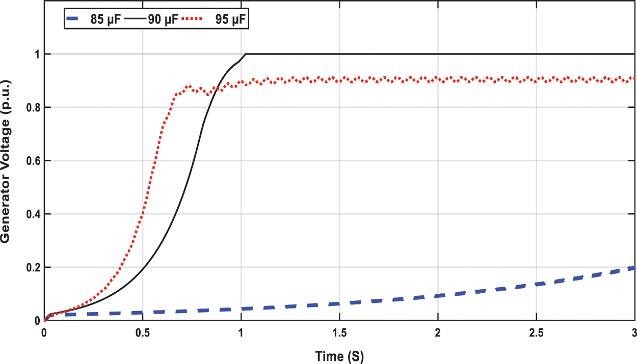
Figure 5: Generator voltage at N =1200 rpm and C = 85, 90 and 95 µF
5.2 System Performance with Speed Variation
The speed is changed in this case. This change will affect the magnitude of the output voltage. So a variation of the capacitance should be applied to regulate that voltage due to the speed variation through regulating PWM by the output signal from the POI controller. The capacitance required at each speed is calculated using HS and PSO. Seven speeds inside the speed operating range from 1200 rpm to 1500 rpm are selected, at each speed, the HS and PSO algorithms are utilized to find the capacitance required with minimum objective function introduced in (1). The prime mover speed with the required capacitance for the excitation at different speeds is given in Tab. 1.
Table 1: Prime mover speed with the corresponding capacitance
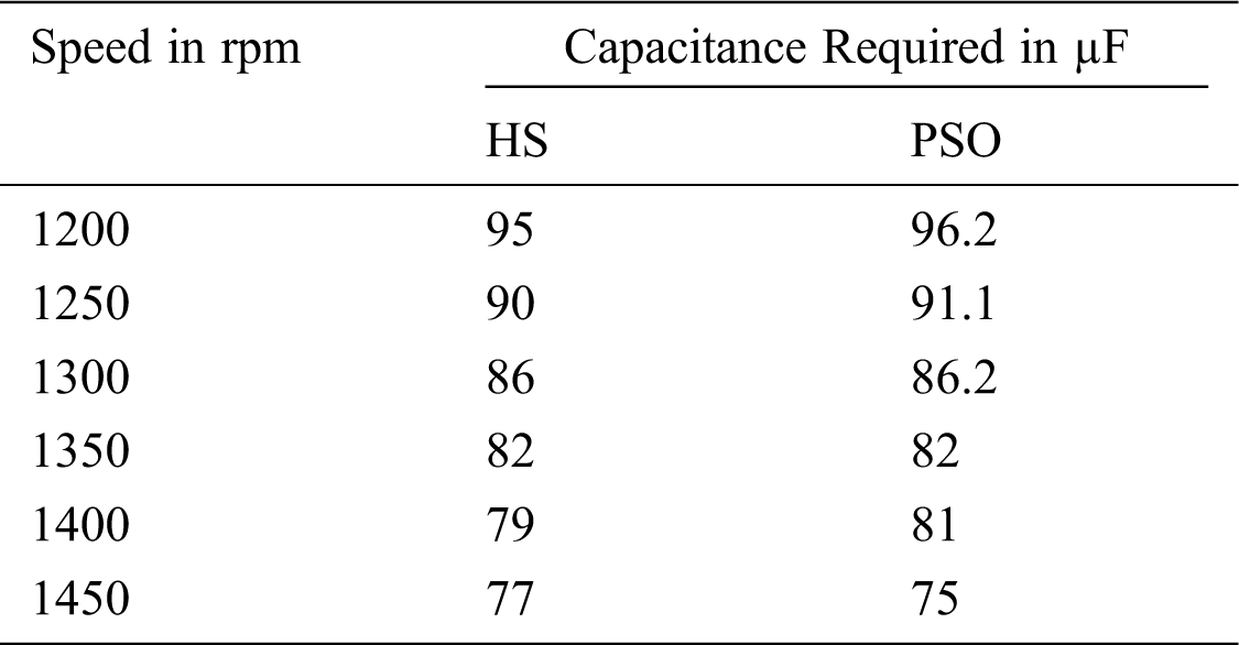
Some speeds are selected from the speed range to test the system performance with the results obtained from HS and PSO.
The convergence of PSO and HS optimization techniques is given in Fig. 6. The convergence time for PSO and HS are 0.3 s and 0.32 s respectively.
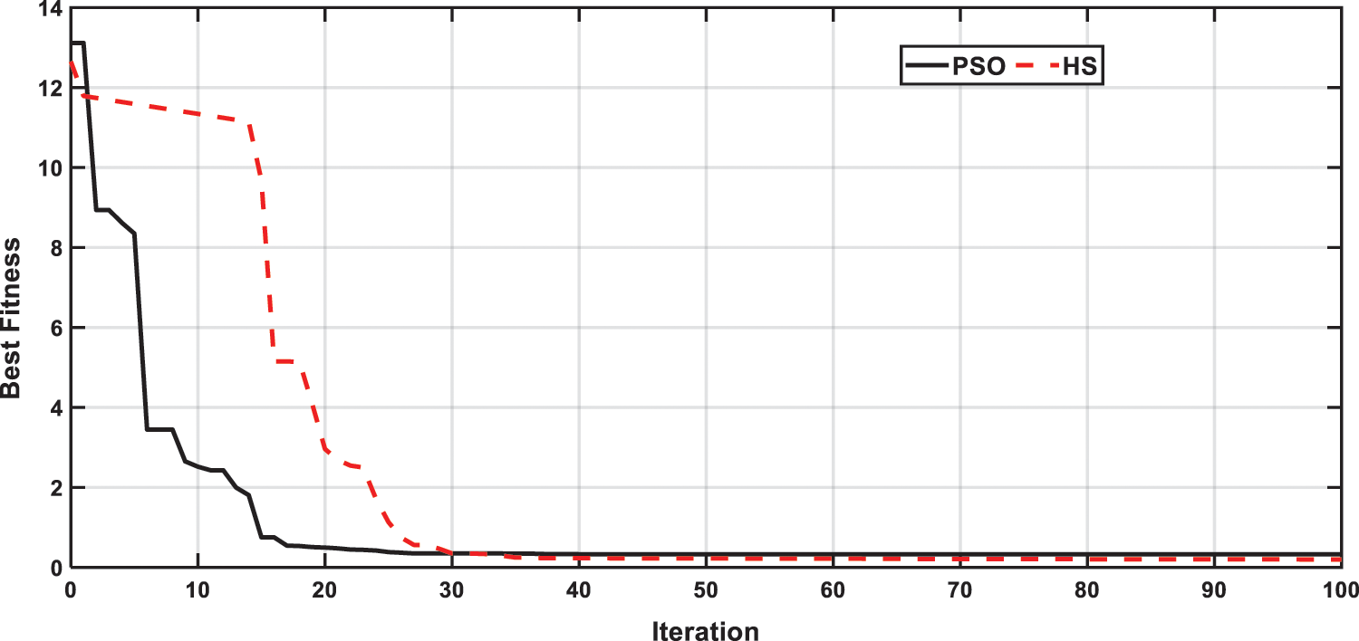
Figure 6: Convergence of PSO and HS
In this case, the speed is decreased from the rated speed of 1500 rpm to 1200 rpm as shown in Fig. 5. The controller succeeded at changing the capacitance to the level required to keep the voltage at 1 p.u as depicted in Fig. 6. With the rated value of the capacitance, 75 µF, a decrease in the output voltage to 0.89 p.u. is occurred as the speed decreases at 1.5 sec as in Fig. 7.

Figure 7: Speed variation from 1500 to 1200 rpm at 1.5 sec
In this case, the capacitance value is extracted from the fixed capacitance obtained from HS as controlled SPWM used to short circuit the capacitor at specific intervals. At the rated speed the controller succeeds at regulating the capacitance at 75 µF, while at 1200 rpm; the capacitance is changed to 95 µF.
The duty cycle used for this test case is shown in Fig. 8. The duty cycle has ranged from 0% to 100%. 100% means that the switch is opened so that the capacitor is not short circuit during this interval and the maximum capacitance is connected to the auxiliary winding. At the rated speed of 1500 rpm from 1 s to 1.5 s, the duty cycle is 88%. From 1.5 s to 3 s, the speed decreased to the minimum speed at which the generator can be excited and build up voltage occurs, 1200 rpm, as explained in the last section, the duty cycle changes to 100% as the switch in the off state so the capacitance of 95 µF is always connected with this value to the generator. This means that the capacitor will not be short circuit, so the capacitance value of 95 µF will be connected to the generator that fulfills the excitation requirement, as illustrated before.
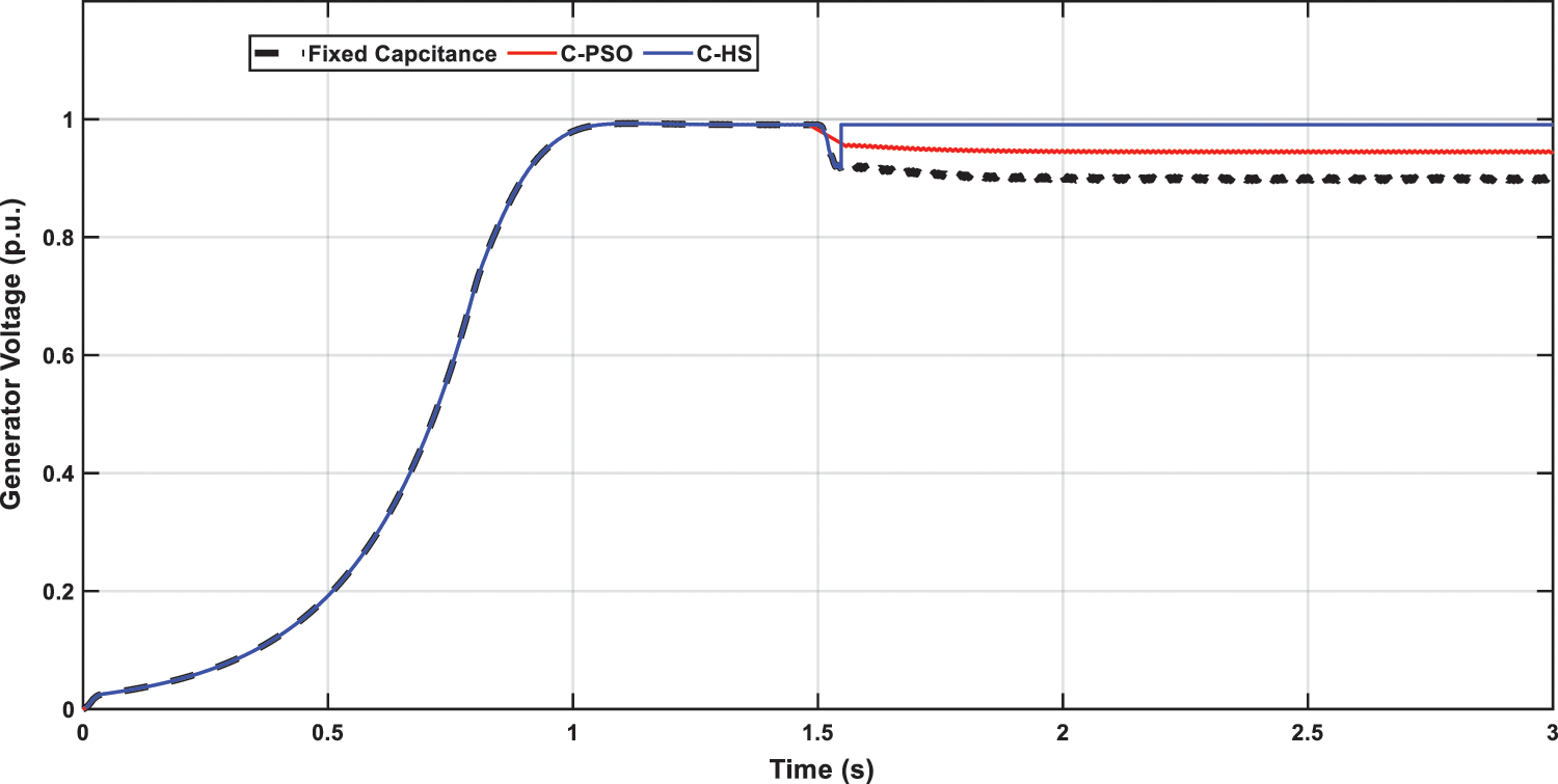
Figure 8: Generator voltage with speed variation at fixed and variable capacitances
Another step in the wind speed drive, the prime mover of the generator, among the seven test cases in Tab. 1, will be applied to test the proposed control system’s capability to regulate the output voltage. The speed pattern is shown in Fig. 9.
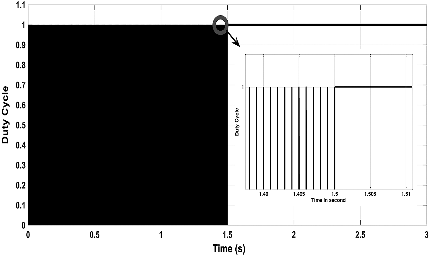
Figure 9: The duty cycle for the switch control using HS
The controller can keep the voltage at 1 p.u during these speed variations as in Fig. 10. Another advantage is added to the controller in that it decreases the harmonics distortion to lower levels of about 0.1% as in Fig. 11. Moreover, at the highest change in the speed from 1450 rpm to 1200 rpm, the minimum overshoot due to this decrease is 20% that adds another advantage to the control method.

Figure 10: Speed pattern
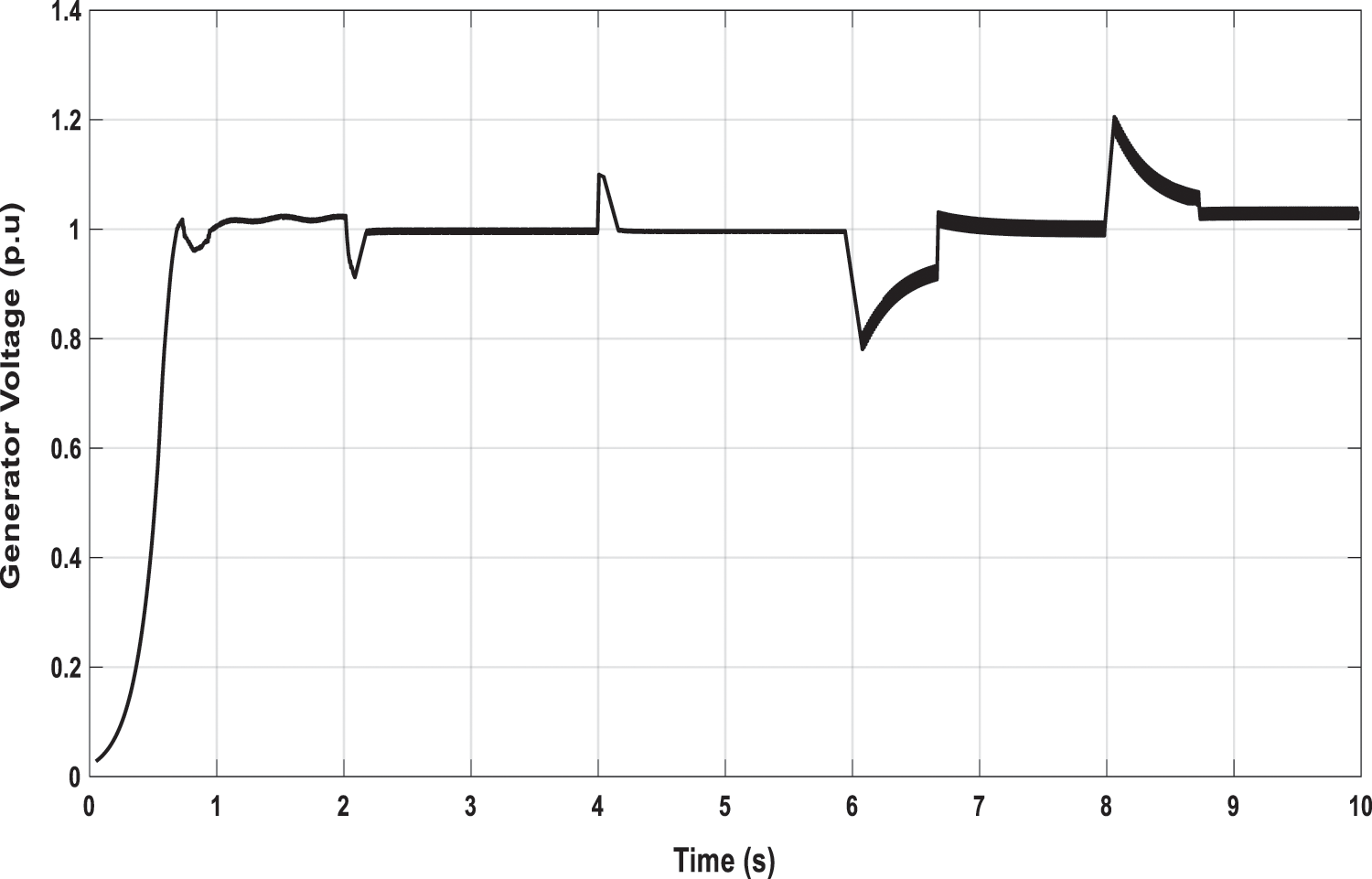
Figure 11: Generator voltage at different generator speeds using HS
This paper introduces a simple control method for self-regulation single-phase induction generator for wind energy conversion system-based remote load applications. The proposed method exploits the virtual capacitance changing extracted from a fixed capacitor to regulate the generator’s output voltage at different wind speeds using SPWM technique to short circuit the capacitor during controlled duty cycles. The capacitance required for exciting the generator, in order to minimize the difference between the output voltage and a reference voltage, is calculated using HS optimization algorithm.
Acknowledgement: This study was funded by the Deanship of Scientific Research, Taif University, KSA [Supporting Project Number TURSP-2020/34].
Funding Statement: This study was funded by the Deanship of Scientific Research, Taif University, KSA [Supporting Project Number TURSP-2020/34.
Conflicts of Interest: The authors declare that they have no conflicts of interest to report regarding the present study.
1. S. Barakat, M. M. Samy, M. B. Eteiba and W. I. Wahba, “Viability study of grid-connected PV/Wind/Biomass hybrid energy system for a small village in Egypt,” Power Syst. Conf. (MEPCONEighteenth Int. Middle East, vol. 2016, pp. 46–51, 2016. [Google Scholar]
2. M. Ebeed, A. Ali, M. I. Mosaad and S. Kamel, “An improved lightning attachment procedure optimizer for optimal reactive power dispatch with uncertainty in renewable energy resources,” in IEEE Access, vol. 8, pp. 168721–168731, 2020. [Google Scholar]
3. M. M. Samy, Mohamed I. Mosaad and S. Barakat, “Optimal economic study of hybrid PV-wind-fuel cell system integrated to unreliable electric utility using hybrid search optimization technique,” International Journal of Hydrogen Energy, vol. 46, no. 20, pp. 11217–11231, 2021. [Google Scholar]
4. J. Faiz, A. A. Dadgrae and S. Horning, “Design of a three-phase self-excited induction generator,” IEEE Transactions on Energy Conversion, vol. 10, no. 3, pp. 516–523, 1995. [Google Scholar]
5. Y. J. Wang and Y. S. Huang, “Analysis of a stand-alone three-phase self-excited induction generator with unbalanced loads using a two-port network model,” IET Electric Power Applications, vol. 3, no. 5, pp. 445–452, 2009. [Google Scholar]
6. M. I. Mosaad, A. Alenany and A. Abu-Siada, “Enhancing the performance of wind energy conversion systems using unified power flow controller,” IET Genneration Transsions $ Distribution, vol. 10, no. 10, pp. 1922–1929, 2019. [Google Scholar]
7. W. Slimane, M. T. Benchouia, S. Drid, A. Benamor and A. Golea, “Power maximization of a variable speed wind energy conversion system based on a double fed induction generator connected to the grid,” in 020 1st Int. Conf. on Communications, Control Systems and Signal Processing (CCSSPEL OUED, Algeria, pp. 1–6, 2020. [Google Scholar]
8. M. I. Mosaad, “Model reference adaptive control of STATCOM for grid-integration of wind energy systems,” IET Electric Power Applications, vol. 12, no. 5, pp. 605–613, 2018. [Google Scholar]
9. M. I. Mosaad, A. Abu-Siada and M. Elnaggar, “Application of superconductors to improve the performance of DFIG-based WECS,” IEEE Access Journal, vol. 7, no. 1, pp. 103760–103769, 2019. [Google Scholar]
10. M. I. Mosaad, N. I. Elkalashy and M. G. Ashmawy, “Integrating adaptive control of renewable distributed Switched Reluctance Generation and feeder protection coordination,” Electric Power Systems Research, vol. 154, no. 5, pp. 452–462, 2018. [Google Scholar]
11. M. I. Mosaad, “Direct power control of SRG based-wind energy conversion systems using optimised fractional-order PI,” IET Electric Power Applications, vol. 14, no. 3, pp. 409–417, 2020. [Google Scholar]
12. M. I. Mosaad and F. Salem, “Adaptive voltage regulation of self excited induction generator using FACTS controllers,” International Journal of Industrial Electronics and Drives-Inderscience Publishers, vol. 1, no. 4, pp. 219–226, 2014. [Google Scholar]
13. B. Palle, M. G. Simoes and F. A. Farret, “Dynamic simulation and analysis of parallel self-excited induction generators for islanded wind farm systems,” IEEE Transactions on Industry Applications, vol. 41, no. 4, pp. 1099– 1106, 2005. [Google Scholar]
14. J. L. Bhattacharya and J. L. Woodward, “Excitation balancing of self-excited induction generator for maximum output,” Proc. of Instrumentation Electrical Engineering C, vol. 135, no. 2, pp. 88–97, 1988. [Google Scholar]
15. U. K. Madawala, T. Geyer, J. B. Bradshaw and D. M. Vilathagamuwa, “Modeling and analysis of a novel variable-speed cage induction generator,” IEEE Transactions on Industrial Electronics, vol. 59, no. 2, pp. 1020–1028, 2012. [Google Scholar]
16. S. Rajendran, U. Govindarajan, A. B. Reuben and A. Srinivasan, “Shunt reactive VAR compensator for grid-connected induction generator in wind energy conversion systems,” IET Power Electronics, vol. 6, no. 9, pp. 1872–1883, 2013. [Google Scholar]
17. U. K. Kalla, B. Singh and S. S. Murthy, “Enhanced power generation from two winding single-phase SEIG Using LMDT based decoupled voltage and frequency control,” IEEE Transactions On Industrial Electronics, vol. 62, no. 11, pp. 6934– 6943, 2015. [Google Scholar]
18. M. M. Ahmed and M. Y. Abdelfatah, “Self-regulated single-phase induction generator,” in Int. Conf. On Communication, Computer And Power (ICCCP’09MUSCAT, pp. 15–18, 2009. [Google Scholar]
19. E. Muljadi, Y. Zhao, T. Lui and T. A. Lipo, “Adjustable AC capacitor for a single-phase induction motor,” IEEE Transaction on Industry application, vol. 29, no. 3, pp. 479–485, 1993. [Google Scholar]
20. J. Faiz, A. Jafarian and M. Neekzad, “PSPICE simulation of a capacitor start and triac start single phase induction motor during steady state and transient operations and its experimental verification,” Energy Conversion and Management, vol. 44, no. 3, pp. 479–495, 2003. [Google Scholar]
21. A. Abu-Siada, Mohammed I. Mosaad, Do Won Kim and Mohamed F. El-Naggar, “Estimating power transformer high frequency model parameters using frequency response analysis,” IEEE Transactions on Power Delivery, vol. 35, no. 3, pp. 1267–1277, 2020. [Google Scholar]
22. B. Yang, Y. Chen and Z. Zhao, “Survey on applications of particle swarm optimization in electric power systems,” in 2007 IEEE Int. Conf. on Control and Automation, Guangzhou, China, pp. 481–486, 2007. [Google Scholar]
23. W. S. Hassanein, M. M. Ahmed, M. Osama abed el-Raouf, M. G. Ashmawy and M. I. Mosaad, “Performance improvement of off-grid hybrid renewable energy system using dynamic voltage restorer,” Alexandria Engineering Journal, vol. 59, no. 3, pp. 1567–1581, 2020. [Google Scholar]
24. Z. W. Geem, J. H. Kim and G. V. Loganathan, “A new heuristic optimization algorithm: Harmony search,” Simulation, vol. 76, no. 2, pp. 60–68, 2001. [Google Scholar]
 | This work is licensed under a Creative Commons Attribution 4.0 International License, which permits unrestricted use, distribution, and reproduction in any medium, provided the original work is properly cited. |