DOI:10.32604/iasc.2021.016088
| Intelligent Automation & Soft Computing DOI:10.32604/iasc.2021.016088 | |
| Article |
PSO Based Torque Ripple Minimization Of Switched Reluctance Motor Using FPGA Controller
1Department of Electrical and Electronics Engineering, Mohamed Sathak Engineering College, Ramanathapuram, India
2Department of Electrical and Electronics Engineering, National Engineering College, Kovilpatti, 628503, India
*Corresponding Author: A. Manjula. Email: a.manjuraman1@gmail.com
Received: 22 December 2020; Accepted: 08 March 2021
Abstract: The fast-growing field of mechanical robotization necessitates a well-designed and controlled version of electric drives. The concept of control concerning mechanical characteristics also requires a methodology in which the system needs to be modeled precisely and deals with uncertainty. The proposed method provides the enhanced performance of Switched Reluctance Motor (SRM) by controlling its speed and minimized torque ripple. Proportional-Integral-Derivative (PID) controllers have drawn more attention in industry automation due to their ease and robustness. The performances are further improved by using fractional order (Non-integer) controllers. The Modified Particle Swarm Optimization (MPSO) based optimization approach is employed to acquire the FOPID control parameters for speed and current and the selection of commutation of angles. The performance of SRM has been investigated by considering the Integral Square Error (ISE) of speed and current, which results in minimized torque ripples. In this work, SRM with 8 stator poles and 6 rotor poles is modeled as four-phase in MATLAB/SIMULINK platform. The average output torque and speed of the proposed method are analyzed and compared with the conventional PID controller. The results reveal that MPSO based FOPID controller gives an extreme performance in terms of increased output torque and faster settling time because of its consistent performing capability compared with conventional PID-based controller. The results are validated with an FPGA-based 8/6 SRM setup that employs the PID controller.
Keywords: Fractional order PID controller; switched reluctance motor; modified particle swarm optimization; torque ripple coefficient; FPGA controller
In the recent development of the control and power electronics field, SRM has drawn a significant role in industries. SRM drive has many beneficial characteristics when comparing to those conservative sinusoidal machines. For industry automation, SRM drives play a vital role, acting as a prominent electrical drive [1]. As SRM has no rotor winding and a permanent magnet, its structure becomes simple. It has many distinct characteristics such as minimized cost, robustness, high fault-tolerant capability, and operating under any sensitive environment [2]. Electromagnetic torque is produced based on the theory of variable reluctance. Nevertheless, the primary setback is the higher torque ripple, which leads to severe acoustic noise and vibrations [3]. Therefore, the strategy of reducing the torque ripple in SRM becomes the most contributive research in the field of industry [4].
In the modern era, there are two emerging technologies to improve the average torque of the motor. One method is to renovate the stator and rotor arrangement by developing the mechanical consideration, whereas the next one is to employ the robust control mechanism [5]. Some researchers are proficient in decreasing the torque vibrations by reconstructing the motor design using some specific software platform, leading to the cost expenditure once it comes into operation [6]. The other strategies are based on obtaining a suitable grouping of the operational constraint, which contains input voltage, turn on and turn off angles, excitation current, and the load. A proper current modulation technique for the inverter is usually taken care of to minimize torque ripple [7]. A simple current modification scheme for the inverter is generally employed for reducing the torque ripples in SRM. Adequate commutation instant setting and tuning under various operating conditions are required for achieving a good stator winding current and smooth torque for a switched-reluctance motor (SRM) drive. Dynamic commutation shift controller (DCSC) based on DC-link current ripple minimization for SRM drives are also proposed to minimize the ripples [8]. Torque Sharing Function (TSF) has been used to obtain the static flux linkage characteristics which describe the machine dynamics to determine optimal current profiles to achieve torque ripple reduction with minimal copper losses. [9]. Overlapping regions between the phases being controlled such that direct instantaneous torque control (DITC) and current control (CC) have been implemented simultaneously on different phases [10]. The Lagrange optimization method is used to solve calculating optimal currents in the d–q frame. A neural control scheme is then proposed as an adaptive solution to derive the optimal stator currents giving a constant electromagnetic torque and minimizing the ohmic losses [11]. The performance of the precise speed controller is evaluated and compared with PI and fuzzy logic (FLC) speed controllers. This comparison is based on the values of the rise time, settling time, overshoot, undershoot, speed error in the steady-state, and torque ripples percentage of the three-speed controllers [12]. The mean torque vs. current capability and the torque ripple are investigated, and optimum commutation angles are evaluated in static conditions. The test results confirm the performance analysis computed by the finite element model and shown that the machine could operate in severe faulty mode conditions. However, the limitations of the power electronics allowed the testing of the prototype at only 1/3 of the rated power [13].
2.1 Mathematical Modeling Of SRM Drive
SRM is a kind of stepper motor, which is working under the principle of variable reluctance at airgap. Contrasting with the ordinary DC motor, energy is distributed to stator windings rather than the rotor. The mechanical design has been significantly simplified as power does not have to be delivered to the moving part. In electrical design, a specific switching system is needed to excite the proper stator winding for smooth operation. With modern electronic devices, SRM is a perfect candidate for industrial applications which require high reliability, high efficiency, and high speed. Unlike standard traditional motors, which use a troublesome mechanical commutator to switch the winding current, SRM exploits the electronic position sensor to find out the rotor shaft position and make the solid-state electronics to energize the stator windings to produce the rotational torque. This could provide the chance of dynamic control for pulses and waveshaping. Asymmetric bridge converter is the most appropriate device for powering an SRM [14]. In an asymmetric bridge converter, there are 4 phases corresponding to the stator windings of the SRM drive. In this process, the corresponding phase will be energized only if both the power switches on either side of the phase are switched on. Once the current has reached the reference value, the device is turned off. Hence, the energy developed in the motor is used to maintain the stator current in the same direction until the energy gets exhausted.
In SRM, when the stator phase is getting energized, a low reluctance results in the magnetic circuit. Hence, the rotor pole tends to move towards the low reluctance path, and the rotor pole gets aligned with the stator pole; thereby, torque is developed. The generated torque is also independent of the direction of the stator current. The SRM drive rotates the magnetic field by regularly and successively switching on and off stator windings. Meanwhile, the rotor rotates and trailing the current to stay aligned with the magnetic field to reduce the reluctance of the magnetic flux path. A rotor position sensor will determine the rotor position and provides the information on when and which of the stator phase is to be energized. The rotor position sensor will decide the turn on and turn off instants of the power semiconductor switches used in converters. The position of the rotor has been continuously monitored by sensing the speed feedback. Here, the unaligned rotor position is taken as zero degrees. The rotor movement towards the minimum reluctance position is the cause of the torque production mechanism. No torque will be produced when the field lines are at a right angle to the surface. By energizing the stator phase, the rotor will get attracted; thereby, reducing the reluctance of the magnetic circuit and thus, torque will be produced. By energizing the successive phases of the stator continuously, constant torque is developed [15]. The torque depends on the current and rate of change of inductance with respect to the rotor position [16].
The total torque developed in the SRM is represented as,
The mathematical equation governing the system is written as,
where
Table 1: SRM simulation parameters
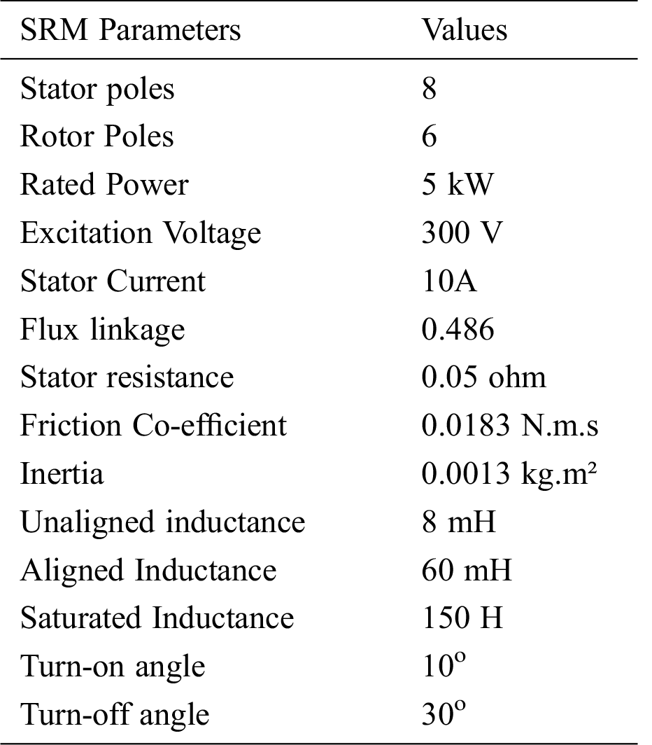
Using the mathematical Eq. (2) that governs the system, the active model of a linear 8/6 SRM, 4 phase with negligible mutual inductance is created in the MATLAB/SIMULINK environment [17]. The parameters used for modeling the SRM in the simulation environment are tabulated in Tab. 1. The value of winding inductance is proportional to the magnetic flux. When flux increases towards saturation, the value of the inductance will also increase. Saturated inductance in Tab. 1 represents the maximum inductance that a particular SRM drive can attain. The manufacturer usually specifies it. At the same time, the stator winding current decides the aligned and unaligned inductance. Hence this value is lower than the saturated inductance value. The pattern of the inductance of 4 phase SRM is as shown in Fig. 1. For motoring action, the stator windings are excited when the slope of inductance ∂L/∂θ is positive. One of the performance measures of SRM is the torque ripple coefficient (
where
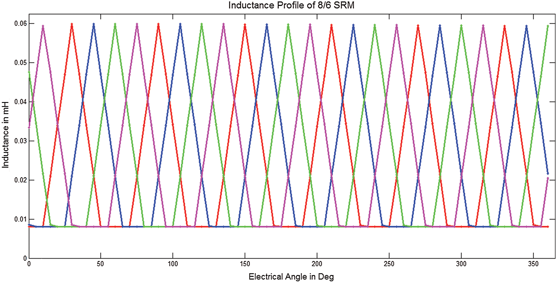
Figure 1: Inductance profile of the four-phase SRM
2.2 Design Of Fractional Order PID Controllers And Commutation angles
The recent research methodologies introduce the opportunity of constructing the methods of differentiation and integration as non-integer orders. Fractional order PID controller has wider flexibility and more degree of freedom to provide appropriate dynamic properties for servo control applications. The following equation is written in Laplace domain, with zero initial conditions, to represent the fractional-order PID controller (4),
Nevertheless, the order of the system has played a vital role in different scientific fields, such as automatic control system, which results in accurate modeling and more flexibility in the design of the control mechanism [18]. In the proposed method of torque ripple minimization, two FOPID controllers, namely speed and current, are employed to extort the speed error and the reference currents for SRM
The transfer function of the speed and current FOPID controllers are generally written in a parallel form as follows in the Eqs. (5) and (6),
where
The commutation angles have also been considered as a significant parameter to evaluate the performance of SRM. The minimized torque ripple and improved efficiency of SRM depend, to a greater extent, on the optimal selection of commutation angles. The commutation angles are properly obtained that the stator winding should not be energized at the negative slope, which yields the generating torque and zero torque, respectively. The flux should be decayed before the negative torque production. This leads to making the commutation angles to be advanced by an angle, which is given by the following Eq. (7).
where,
2.3 Modified Particle Swarm Optimization
Modified Particle Swarm Optimization (MPSO) is a population-based searching method that evolves from the social behavior of birds and fish. PSO algorithm is stochastic in nature as it does not require a derivative of information [20]. Thus there is minimal possibility of local entrapment, but particles can converge prematurely, majorly in the case of larger search space. In this method, particles are moving in a multidimensional search space [21]. During movement, every particle changes its position from its knowledge of neighboring particles, occupying the suitable position found by itself and its neighbors. The swarm particle is described by the nearest particles neighboring and its experience.
Let
where,
The inertia weight is modified at each iteration that makes this algorithm as Modified Particle Swarm Optimization [22]. The velocity adjusted for each move of particles, which is shown in Eq. (9).
In the conventional PSO algorithm, for every evolution step, the positions for each particle are updated by dynamically tracking its corresponding historical optimal position and the optimal position of the swarm population. In this method, the maximum velocity
3 Proposed System For Torque Ripple Minimization
A new methodology proposed is shown in Fig. 2, which allows the speed and current regulation and commutation angles using the MPSO algorithm with minimized torque ripple. Here the FOPID controller structures are incorporated for the proposed controllers. The optimum combination of the twelve parameters such as proportional, integral, and derivative gains (
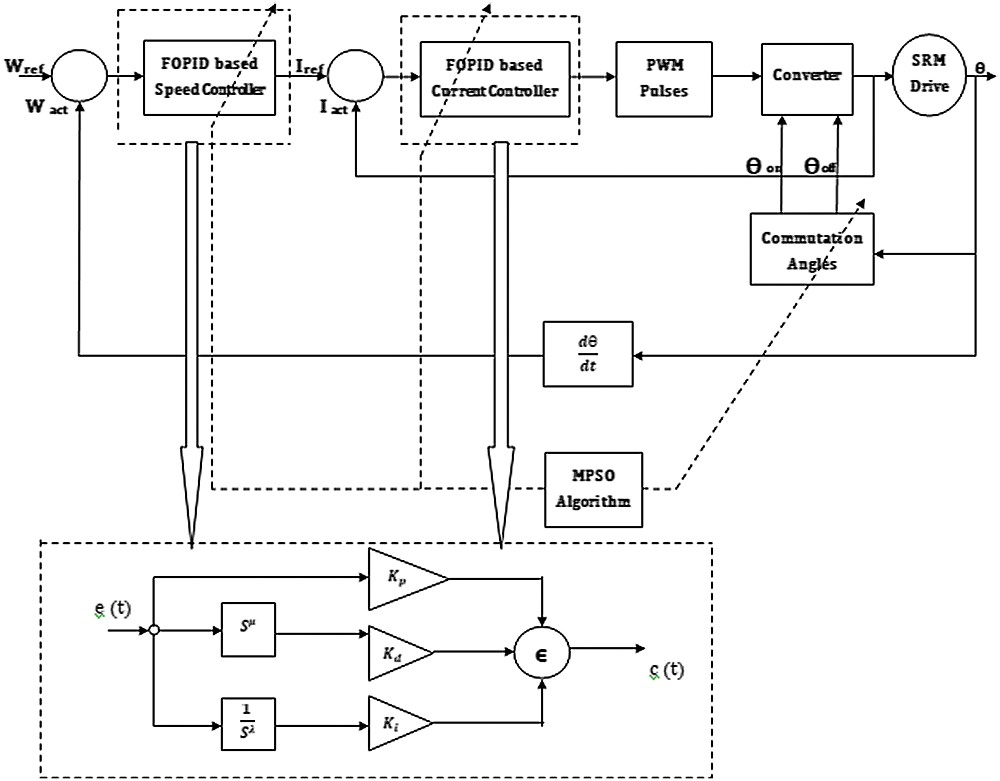
Figure 2: Proposed system
4 Design Of FOPID Controllers And Commutation Angles
In this work, the control mechanism is used to obtain the twelve optimal values of parameters such as proportional, integral, and derivative gains, non-integer order of integration, and differentiation of both speed and current FOPID controllers along with commutation angles by MPSO. The objective of the proposed method is to minimize the torque ripples along with the speed control by considering the Integral Square Error (ISE) of speed and current.
4.1 Design Of Speed And Current Controllers
The initial values for all the particles are assigned within the search space, bounded by their lower and upper preset values of all FOPID control parameters as given in the following Eqs. (10) and (11).
Similarly, the order of integration and order of differentiation also have upper and lower limits as follows in Eqs. (12) and (13).
The preset values from Eqs. (10)–(13) have been chosen by the trial and error method.
4.2 Design Of Commutation Angles
For the 8/6 four-phase machine, the positive slope of the inductance profile starts at 10o and ends at 30o. The turn-on and turn-off angles in Tab. 1 are ideal values. The commutation angles are chosen earlier than advancing angles since the current pulses are not ideal due to the inductive nature of motor winding.
In this work, the minimum and maximum limits of commutations angles are taken into account as wide search space and narrow search space. For wide search space, the minimum and maximum limits of commutations angles are selected as in Eq. (14),
The minimum and maximum limits of commutations angles for narrow search space are defined by incorporating the advancing angle as 3o (0.0524rad) using the Eq. (7). Hence the minimum and maximum limits of commutations angles are selected as in Eq. (15).
For the 8/6 four-phase machine, the positive slope of the inductance profile starts at 10o and ends at 30o. Hence the theta-on and theta-off should be carefully chosen during the positive slope of inductance to produce positive torque. For wide search space and narrow search space, the upper limit is only set as 30o, and there is no possibility of negative torque.
The Integral square error of FOPID controllers for speed and current are evaluated by the following Eqs. (16) and (17)
where
To obtain optimum speed tracking and torque ripple minimization, in this method, reduction of combined integral square error of speed, current, and torque ripple is taken as objective. The normalized sum of the combined integral square error of controllers is formulated as a performance index (J) given in Eq. (18).
For convenience
In this paper, a four-phase 8/6 SRM motor is modeled in simulation by Matlab/Simulink environment. The load torque is taken as 3 Nm, and the speed of SRM is 2000 RPM. The source voltage of the converter is 300V, PWM switching frequency is 10 kHz, and the calculation step time is 1e-4 second. Hence the switching frequency of the converter is 10 kHz. In this work, the appropriate constraints such as the population size is chosen as 60, and the stopping criteria, as well as the number of functional evaluations, are set as 6000. The optimum values of proportional, derivative, and integral gains and the fractional non-integer order of integration and differentiation for both speed and current controller along with the turn-on and turn-off angles, are listed in Tab. 2. In general, the optimal range for population size is between 50 – 100, and functional evaluation is 5000-10000. Most of the researchers are using between these ranges irrespective of the problems they are handling. In our problem, the population size and the number of functional evaluations are set as 60 and 6000, respectively. These values are taken on a trial and error basis. These optimal values are obtained by minimizing the Integral Square Error (ISE) of speed and current along with torque ripple as objectives. To acquire a constructive conclusion, many trials with independent populations should be made because of the uncertainty of the MPSO. In this work, 20 independent trials are carried out. The statistical performance such as minimum, the maximum, mean, and standard deviation of the performance measure, ISE for speed, current, and torque ripple coefficient are reported.
Table 2: Optimum parameters of FOPID, PID Controllers and turn-on and turn-off angles
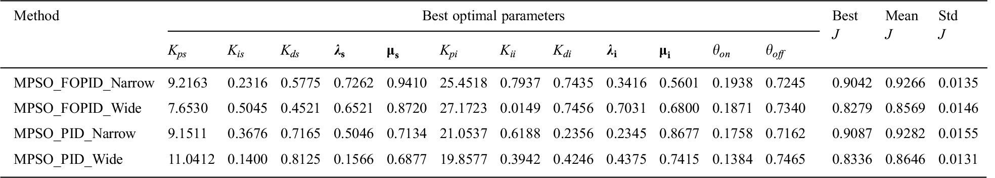
Optimum FOPID parameters for speed, current controllers along with turn-on and turn-off angles, and the statistical performances of performance index J for the 20 independent trials using MPSO are reported in Tab. 2. When comparing performance index J, the FOPID based MPSO with narrow search gives robust performance compared to the traditional PID controller. While considering the performances of all possibilities for wide search space, MPSO gives the consistent performance capability among all other controllers. The standard deviation is also lesser for MPSO based controllers.
Fig. 3 shows the convergence characteristics of various controllers such as MPSO based FOPID and MPSO based PID with narrow search space and wide search space for speed tracking of SRM with torque ripple minimization. When considering Fig. 3, the convergence characteristics in wide search, the MPSO based PID algorithm exhibits many variations in the initial period. If the algorithm is converged at a minimal number of generations, the computation time will be reduced, and the condition will be used for further processing in order to design the gains and parameters for other drives; the drive specifications should be known.
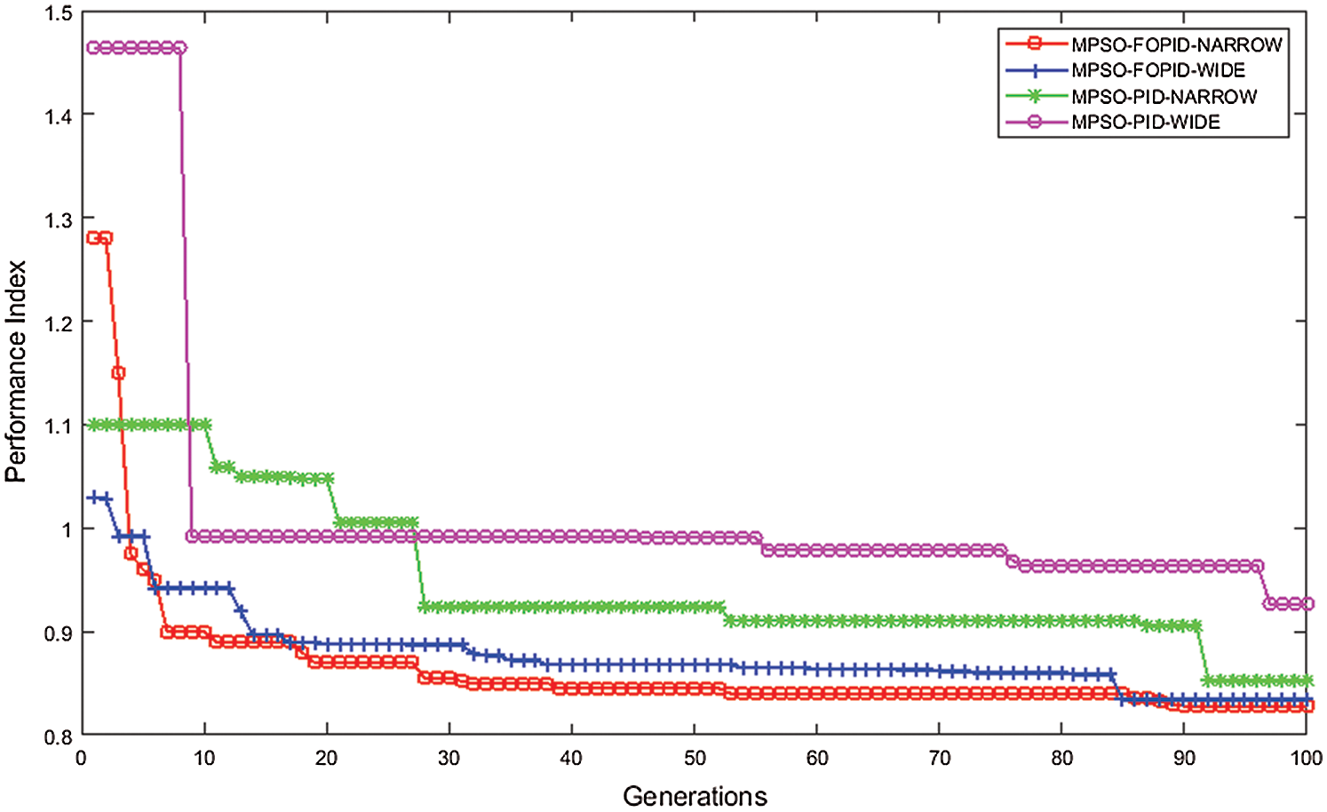
Figure 3: Convergence characteristics of MPSO for different controllers
The convergence characteristics of MPSO based FOPID with both wide and narrow search are smooth compared when it is compared with PID-based MPSO. Among these controllers, MPSO based FOPID with narrow search takes fewer generations to get optimum value and yields better results than the others. The well-designed model is made to run for 0.35 seconds. But in the figure, only the drive speed is shown for 0.35 seconds. For better visualization, the remaining parameters like four-phase currents are shown for 0.3 to 0.35 seconds.
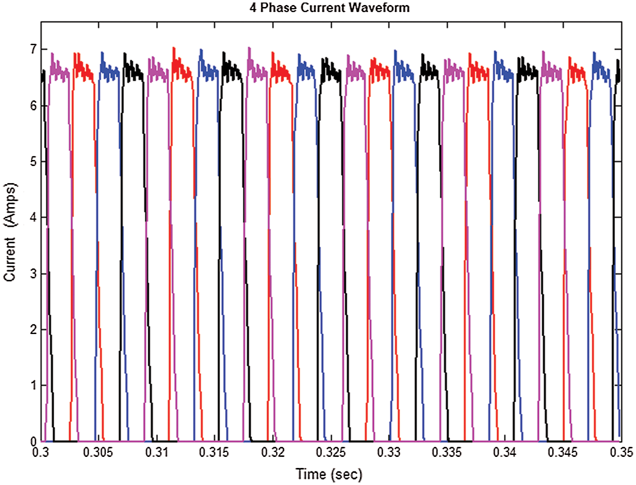
Figure 4: Four Phase currents of SRM drive
Fig. 4 depicts the output results of four-phase currents of the SRM drive. Figs. 5 and 6 the speed and torque characteristics for the 8/6 SRM drive for MPSO based FOPID and PID controller with narrow and wide search spaces. By the suitable selection of proportional, integral, derivative gains, and fractional orders for both speed and current controller along with commutation angles, the torque ripple is decreased as compared with other controllers. The settling time is also enhanced using MPSO based FOPID controllers. From the speed characteristics shown in Fig. 5, it is indicated that the speed can be settled without any variation when the drive is controlled by MPSO based FOPID controller in a narrow search. Because in narrow search space, it has the freedom to find the commutation angles in advance to generate the motoring torque in the positive slope of the inductance.
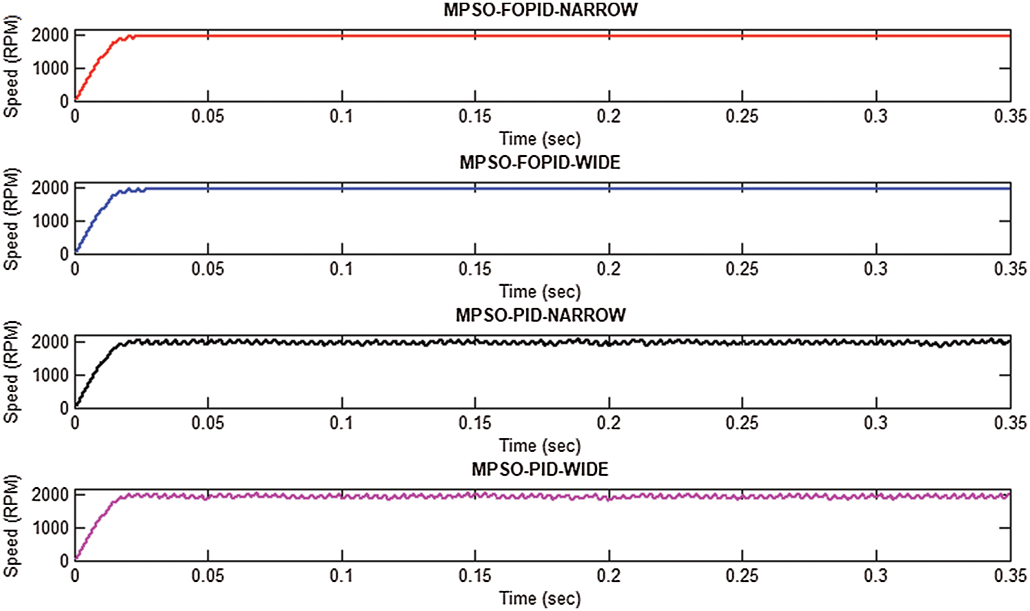
Figure 5: Speed Characteristics of SRM drive for MPSO based Controllers
The comparison between the current waveform of four different controllers has been carried out through the torque comparison shown in Fig. 6. As torque values are proportional to i2, the comparison between them reflects the current waveform comparison. From the torque characteristics of the 8/6 SRM drive, it is explicitly inferred that the narrow search MPSO based FOPID controller provides a minimized torque ripple when compared to conventional MPSO based PID controller. The motor torque should always be greater than the load torque, which (the difference) is only making the machine run. The range for speed is 0-2000 rpm, and torque is only between 0-6. Hence the ripples present in speed are not visible. The ripples should be present in speed also which is proportionate to torque ripples. The motor is simulated for 0.35 seconds. But for clarity, only the portion between 0.325-0.35 second is only shown in Fig. 6. The torque ripples are different for different algorithms, which are listed in Tab. 3.
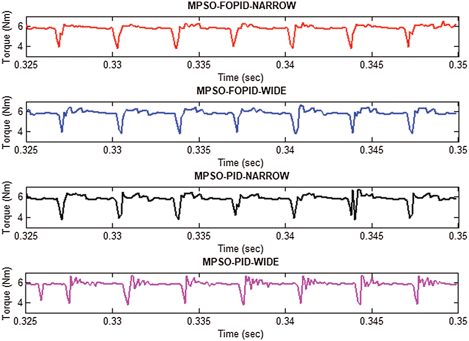
Figure 6: Generated Torque of 8/6 SRM drive
Table 3: Statistical Analysis of SRM with proposed controllers
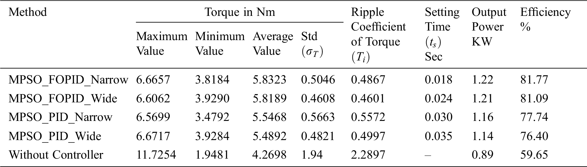
In Tab. 3, the parameters such as minimum, maximum, average values of output torque, and torque ripple co-efficient for MPSO based FOPID and PID controllers are tabulated from statistical analysis. It also depicts the standard deviation of output torque, settling time, output power, and efficiency of the proposed methodologies. The results clearly reported that the average output torque is increased. The torque ripple coefficient and standard deviation of output torque are reduced for MPSO based FOPID controller compared with the PID controller. The increased output torque yields improved output power, which will make the machine more efficient. MPSO based controller gives a better and consistent performance. The drive speed is also superior for MPSO based FOPID controller with narrow search space.
Fig. 7 shows the hardware model of four-phase SRM in order to employ the real-time prototype with minimized torque ripple. The well-designed setup is constituted with a four-phase SRM attached to a loading machine with an IGBT power converter module and an FPGA Spartan-6 XC6SLX9 processor-based controller along with an absolute shaft encoder interfaced to the processor with a speed of 20 MHz. The stator windings in the setup are constructed in such a way that there is no mutual coupling between each phase due to its low-level cross slot leakage flux. In this regard, the mutual coupling effect could be neglected. The experimental conditions are almost similar to simulation conditions. The source voltage is 300V, PWM switching frequency is 10 kHz, and the calculation step time is 1e-4 second.
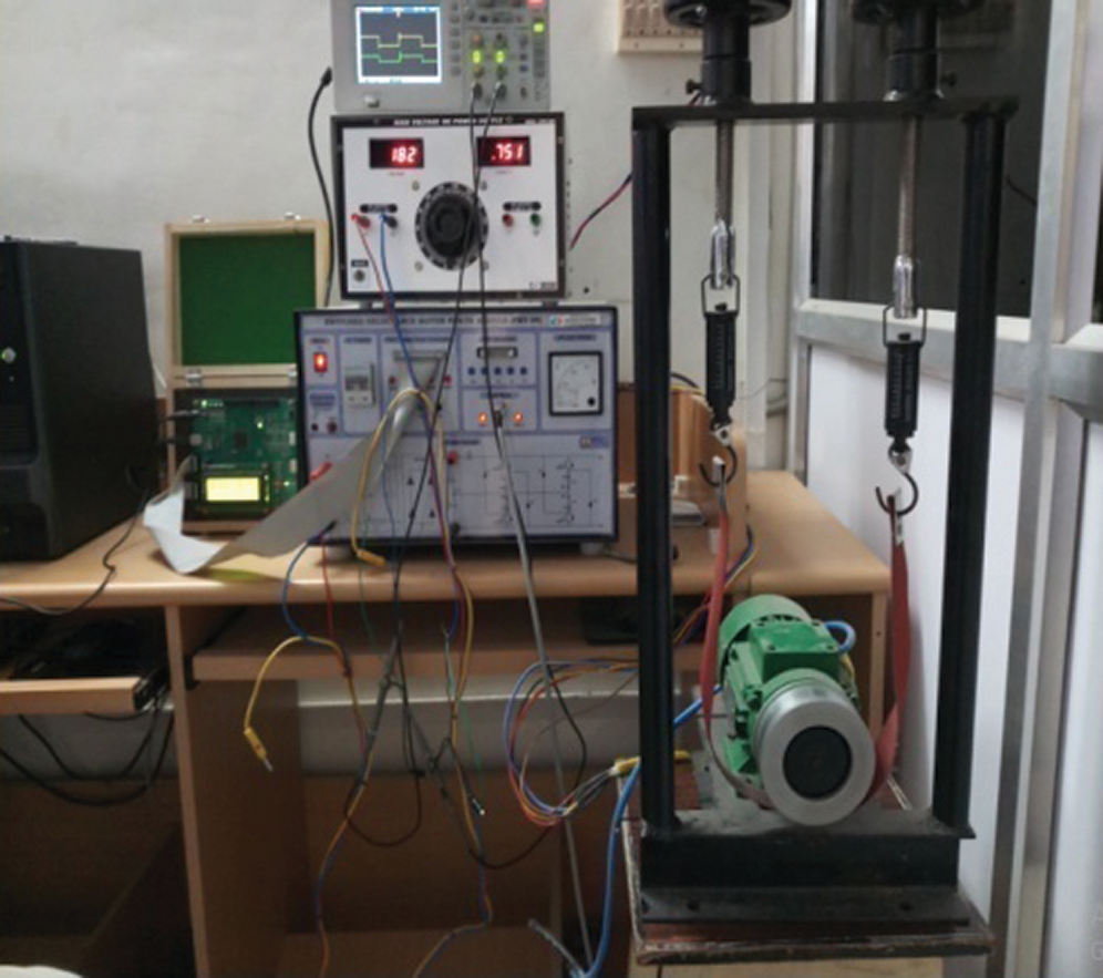
Figure 7: The hardware setup of the 8/6 SRM drive
The optimal parameters obtained in the simulation results of the MPSO based PID controller with narrow search space are set as the controller parameters. The current waveforms shown in Figs. 8a and 8b are four-phase currents obtained in the setup (indicated every two-phase). The results that the ripples in the current waveforms are drastically reduced, resulting in lesser torque ripples. The optimal parameters arrived in the simulation results are given as inputs to the hardware. The results are better than the simulation results. This may be due to the reliability, precision of the driver setup. In Fig. 8, the four-phase currents are separately given. But in Fig. 4, all are merged and presented in a single plot. In SRM, each phase is excited separately. Hence the influence of the commutation period is much more influencing than current ripples. So that only, therefore this work also considered the commutation angles (turn on and turn off) as design parameters. As torque values are proportional to i2, the comparison between them reflects the same as the current waveform comparison. In the conventional PSO algorithm, for every evolution step, each particle's position is updated by dynamically tracking its corresponding historical optimal position and the optimal position of the swarm population. The computation time for narrow search space is lower than wider search space. The narrow search demands prior knowledge but results better.
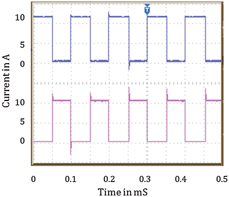
Figure 8: Four phase current of SRM drive
In this work, novel controlling techniques employed for torque ripple minimization along with speed tracking of switched reluctance motor using FOPID based a controller which was tuned by Modified Particle Swarm Optimization (MPSO). This control methodology gives suitable values for twelve operating parameters such as proportional, derivative, integral gains, and non-integer fractional orders for both speed and current controller, along with an optimal selection of commutation angles. The results reveal that the MPSO algorithm gives consistent performance by means of lesser performance index, lesser ISE of speed, current, and minimized torque ripple and standard deviation compared with FOPOID based MPSO and PID based MPSO. Between these controllers, MPSO based FOPID gives better results since the performance of the PID controller is not consistent. It is also observed that torque ripple coefficient and standard deviation are reduced, and mean torque is increased by MPSO based FOPID controllers as compared with PID controller and without controllers. The speed tracking capability is also superior for the MPSO based FOPID controllers. From that, MPSO based controller gives a better and consistent performance than the traditional PID controller. The results are validated with FPGA based 8/6 SRM setup, which employs a PID controller.
Funding Statement: The author(s) received no specific funding for this study.
Conflict of Interest: The authors declare that they have no conflicts of interest to report regarding the present study.
1. M. Alrifai, M. Zribi, M. Rayan and R. Krishnan, “Speed control of switched reluctance motors taking into account mutual inductances and magnetic saturation effects,” Energy Conversion and Management, vol. 51, no. 6, pp. 1287–1297, 2010. [Google Scholar]
2. H. Hannoun, M. Hilairet and C. Marchand, “High performance current control of a switched reluctance machine based on a gain-scheduling PI controller,” Control Engineering Practice, vol. 19, no. 11, pp. 1377–1386, 2011. [Google Scholar]
3. M. N. Anwar, I. Husain and A. V. Radun, “A comprehensive design methodology for switched reluctance machines,” IEEE Transactions on Industry Applications, vol. 37, no. 6, pp. 1684–1692, 2001. [Google Scholar]
4. M. Hajatipour and M. Farrokhi, “Adaptive intelligent speed control of switched reluctance motors with torque ripple reduction,” Energy Conversion and Management, vol. 49, no. 5, pp. 1028–1038, 2008. [Google Scholar]
5. Y. Zheng, H. Sun, Y. Dong and W. Wang, “Torque ripple minimization with current oriented method for switched reluctance motor,” in IEEE Conf. on Electrical Machines and Systems, Seoul, Korea, pp. 1640–1644, 2007. [Google Scholar]
6. C. Elmas and T. Yigit, “Genetic PI controller for a switched reluctance motor drive,” in Turkish Sym. on Artificial Intelligence and Neural Networks, Canakkale, Turkiye, pp. 1–10, 2003. [Google Scholar]
7. N. Inanc and V. Ozbulur, “Torque ripples minimization of a switched reluctance motor by using continuous sliding mode control technique,” Electric Power Systems Research, vol. 66, no. 3, pp. 241–251, 2003. [Google Scholar]
8. H. N. Huang, K. W. Hu and C. M. Liaw, “Switch-mode rectifier fed switched-reluctance motor drive with dynamic commutation shifting using DC-link current,” IET Electric Power Applications, vol. 11, no. 4, pp. 640–652, 2017. [Google Scholar]
9. H. Li, Berker Bilgin, Ali Emadi, “An improved torque sharing function for torque ripple reduction in switched reluctance machines,” IEEE Transactions on Power Electronics, vol. 34, no. 2, pp. 1635–1644, 2019. [Google Scholar]
10. T. Husain, A. Elrayyah, Y. Sozerand and I. Husain, “Husain unified control for switched reluctance motors for wide speed operation,” IEEE Transactions on Industrial Electronics, vol. 66, no. 5, pp. 3401–3411, 2019. [Google Scholar]
11. N. Saha, A. K. Panda and S. Panda, “Speed control with torque ripple reduction of switched reluctance motor by many optimizing liaison technique,” Journal of Electrical Systems and Information Technology, vol. 5, no. 3, pp. 829–842, 2018. [Google Scholar]
12. M. Tursini, M. Villani, G. Fabri and L. Di Leonardo, “Di Leonardo A switched-reluctance motor for aerospace application: Design, analysis and results,” Electric Power Systems Research, vol. 142, no. 6, pp. 74–83, 2017. [Google Scholar]
13. Y. Q. Chen, I. Petras and D. Xue, “Fractional order control – A tutorial,” in Proc. ACC ’09. American Control Conf., pp. 1397–1411, 2009. [Google Scholar]
14. N. C. Sahoo, S. K. Pandaand and P. K. Dash, “A current modulation scheme for direct torque control of switched reluctance motor using fuzzy logic,” Mechatronics, vol. 10, no. 3, pp. 353–370, 2000. [Google Scholar]
15. L. Kalaivani, P. Subburaj and M. W. Iruthayarajan, “Artificial Intelligence based Control for Torque Ripple Minimization in Switched Reluctance Motor Drives,” Journal of Acta Scientiarum Technology, vol. 36, no. 1, pp. 33–40, 2013. [Google Scholar]
16. F. Soares and P. J. C. Branco, “Simulation of a 6/4 switched reluctance motor based on Matlab/Simulink environment,” IEEE Transactions on Aerospace and Electronic Systems, vol. 37, no. 3, pp. 989–1009, 2001. [Google Scholar]
17. M. Hany, S. M. Muyeen and J. Tamura, “Torque ripple minimization of axial laminations switched reluctance motor provided with digital lead controller,” Energy Conversion and Management, vol. 51, no. 12, pp. 2402–2406, 2010. [Google Scholar]
18. E. Edet and R. Katebi, “On Fractional-order PID Controllers,” IFAC- Papers Online, vol. 51, no. 4, pp. 739–744, 2018. [Google Scholar]
19. J. Z. Shi, “A fractional order General Type-2 Fuzzy PID controller Design Algorithm,” IEEE Access, vol. 8, pp. 1–22, 2020. [Google Scholar]
20. J. H. Lee, J. Song, D. Kim, J. Kim, Y. Kim et al., “Particle swarm optimization algorithm with intelligent particle number control for optimal design of electric machines,” IEEE Transactions on Industrial Electronics, vol. 65, no. 2, pp. 1791–1798, 2018. [Google Scholar]
21. Y. Xuerong, C. Hao, L. Huimin, C. Xinjun and Y. Jiaxin, “Multi-objective optimization design for electromagnetic devices with permanent magnet based on approximation model and distributed cooperative particle swarm optimization algorithm,” IEEE Transactions on Magnetics, vol. 54, no. 3, pp. 1–5, 2018. [Google Scholar]
22. T. Guan, F. Han and H. Han, “A modified multi-objective particle swarm optimization based on levy flight and double-archive mechanism,” IEEE Access, vol. 7, pp. 183444–183467, 2019. [Google Scholar]
 | This work is licensed under a Creative Commons Attribution 4.0 International License, which permits unrestricted use, distribution, and reproduction in any medium, provided the original work is properly cited. |