DOI:10.32604/iasc.2021.018256
| Intelligent Automation & Soft Computing DOI:10.32604/iasc.2021.018256 | |
| Article |
A General Technique for Real-Time Robotic Simulation in Manufacturing System
1Department of Computer Science and Information Management, Providence University, Taichung, 433303, Taiwan
2Department of Computer Science and Information Engineering, Advanced Institute of Manufacturing with High-Tech Innovations, National Chung Cheng University, Chiayi, 621005, Taiwan
*Corresponding Author: Ting-Hsuan Chien. Email: thchien0616@pu.edu.tw
Received: 02 March 2021; Accepted: 17 April 2021
Abstract: This paper describes a real-time simulator that allows the user in the factories to simulate arbitrary interaction between machinery and equipment. We discussed in details not only the general technique for developing such a real-time simulator but also the implementation of the simulator in its actual use. As such, people on the production line could benefit from observing and controlling robots in factories for preventing or reducing the severity of a collision, using the proposed simulator and its related technique. For that purpose, we divided the simulator into two main models: the real-time communication model and the simulation model. For the communication model, we present the distributed messaging server structure and the database semaphore technique for handling the real-time peer-to-peer (P2P) connections and control. For the simulation model, we used parallel programming and the general-purpose GPU (GPGPU) technique to speed up the processing time of the simulation. In the paper, we exhaustively explain how the simulator’s techniques are designed and implemented and verify two real world models with robots and robot-operating systems (ROS). Moreover, we compare the results between our technique and the traditional method.
Keywords: Smart factory; cyber-physic system; general-purpose graphics processing units
The concept of “Industry 4.0” was first proposed in the 2011 EMO Hannover, it brought new business models with smart manufacturing by integrating the computing, Cyber-Physical System (CPS), and Internet of Things (IoT) in the traditional manufacturing process [1]. Since then, the whirlwind of Industry 4.0 began to sweep across the the world, and the traditional machine in the factory has been replaced gradually by the combination of controllers, sensors, and computers.
The robotic arm is a cogent reason why we need the aforementioned technique in the manufacturing system. In the factory, the robotic arm is critical because of the rapid throughput and the product quality requirements, and it has become an important symbol of national industrialization. Also, with the rising labor costs and the decreasing threshold of robot manufacturing, the development of the robotics and related equipment has received more attention from all walks of the world. From a survey of 2018 automatica trend index, a total mount of 7,000 employees in seven countries were asked how robots and digitization are changing the working world, and the result shows that most employees believe that automatic robots offer the opportunity to qualify for higher-skilled work. Beside, the evolution calls for targeted training and employees’ further education.
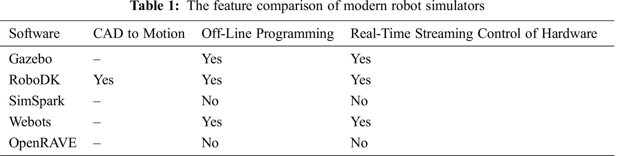
Sine the robotic arms(or robots) are important in the factory of future, we’ll face a new problem of how to work with them. Therefor, the simulation of the robots and the targets becomes an important issue when humans or machines work with the robots. Based on the simulation, we can evaluate different robots and victims during the design phase of industrial systems and lead to better decisions. Besides, it supports module development in replacing unavailable robots and machines (e.g., broken or used by another person) or in long-running experiments (e.g., learning tasks [2]). In addition, the robot programs inside a simulator offer the possibility to debug and test the result during execution directly, which is a great supplement when the platforms do not provide any direct debugging facilities. Tab. 1 shows the features of modern robot simulators. We can notice that these simulators only focus on robots but not on the composition of the manufacturing system.
Another challenge in the simulation systems is the communications between robots and machines, it also fits the fiels of CPS and IoT in Industry 4.0. In the factory, we can use wireless networks to provide adequate communication facilities without a particular structure or restrictions. However, if the device is faced with conditions or high load, the network needs to be carefully used to better exploit the capabilities without any overloading. In this paper, we propose a real-time approach to communicate for the solving the situation in our system.
Obviously, robots will be an essential part of our daily life as smart assistants in the factory. As a regular part of the further applications, the robot’s operation should consider very dynamic, unstructured, and partially unknown environments, co-working with a human user, preventing unnecessary collisions, handling the physical contacts in a general way, and responsibly for sensor-based motions. This paper will introduce our real-time simulator and the related technique to solve the above issue, and compare the result with the traditional way by the use case in the real world.
Craig R. Carignan mentioned the robotic arm in 2002 as an automatic control device that mimics the human arm function and can perform various tasks. The robotic system has multiple joints that allow motion in a flat or three-dimensional space or movement with linear displacement. The robotic structure consists of a mechanical body, a controller, a servomechanism, and a sensor, and then the program sets a specified action according to the operation requirements.
An electric motor drives the operation of the robot to move one arm, open or close a clip, and pass accurate feedback to the programmable logic controller. Those automatic device are mainly used to complete the “wrist and hand” movements. It can be controlled by the skilled operator’s operation sequence and can perform the correct regular operation as many times as possible. The movement principle between different joints can be divided into the right angle coordinate type, the cylindrical coordinate type, the polar coordinate type, and the joint coordinate type. At present, four prominent industrial robots [3], i.e., KUKA in Germany, ABB in Switzerland, and Fanuc and Yaskawa in Japan, are the most well-known manufacturers in the field of the robotic arm.
2.1 Robot in Manufacturing System
With the advent of Industry 4.0, robots are no longer pre-programmed and no need to set their repetitive work individually [1,4]. Thus, as smart manufacturing tasks become more adapted and more flexible, the development of intelligent manufacturing systems has shown great promise. Machines are less likely to be pre-configured through traditional teaching methods but perform variable tasks and respond to unexpected environments and operations. Besides, smart manufacturing also requires the system to dynamically schedule these machine jobs based on workload and received tasks.
Different from standard manufacturing processes, intelligent manufacturing provides the advantages of a distributed network machine that can accomplish different tasks through collaboration. The frame design of the smart factory is shown in Fig. 1 [5]. At a low level, robotic devices can be developed into components flexible in the system and be reused in multiple manufacturing processes. As noted above, robotic arms are highly unrelated in platforms such as operating systems, programming languages, or communication interfaces. Therefore, in some researches, they use middleware to create a unified abstraction to enable communication and coordination dynamically between modules [6], which benefits the modification of existing equipment and new material expansion to become an easy job.

Figure 1: The architecture of the factory communication system
On the factory communication system, we can develop many functions for facilitating the use of machines such as human-machine interface, storage management, motion planning, and virtual manufacturing. For example, customers can order products through the human-machine interface with customized requests, e.g., changing to the favorite color and polishing the part’s shape. The system sends these orders to the mission-planning model and utilizes information from the storage management module. As a crucial part of system speed and brainpower, a generic planner based on the simplified Markov Decision Process (RMDP) model can convert the customer’s order into a subtask sequence that can be executed directly by the corresponding robot component. In addition, manufacturing control systems, management systems, and CAD/CAM design plugins for the application are all critical parts of the industrial manufacture process. Our research focuses on the co-work of layers and component-based technologies.
The Robot World Cup (RoboCup) [7], as an example of multi-robot communication, was first held in 1997 to promote research on artificial intelligence and intelligent robot. The RoboCup Medium League (MSL) is a high-level competition where two teams of five robots compete in football. Its rules follow the official FIFA law but with more restrictions on robots and the environment [8]. During the game, the robot communicates only use the wireless network mode. This paper proposes the unicast and multicast communication modes to disable broadcast. According to the experiments, each team’s maximum transmission bit rate is 20% of IEEE 802.11b (2.2 Mbps). However, most of these rules are not enforced in practice and are often accompanied by problems of reduced communication quality. Efficient communication is a critical factor leading to the team’s success during the game, but most teams only schedule their robots by regularly transmitting information but ignore to consider the synchronization.
Therefore, in the worst case, where all robots try to deliver at the same time, causing communication delays and further influencing communication. Meanwhile, other research presents that communication pattern identification is an essential step in developing reusable software [9] by distinguishing between two categories in a cooperative multi-robot system. In addition, robot state transmission is related to the real world’s perception of robots’ sensors. Constantly exchanging these data can enhance the understanding of the world for each robot. On the other hand, synchronous messages are related to the need for robots’ communication to agree and keep the relationship behaviors in sync.
Physical human-computer interaction (pHRI) research [10,11] is a global goal to achieve robotic behavior and work closely with robots. The approach involves a novel mechanical design of the robotic linkage and drive, design of reducing inertia/weight based on compatible components, extensive use of external sensors for quick and reliable identification of human-robot proximity, and the development of human consciousness movement planning and control strategies. One of the pHRI’s core issues is dealing with collisions between robots and humans, whose primary motivation is to limit the human damage caused by physical contact. The workspace should be monitored by using external sensors to avoid undesired collisions to predict Dangerous situations.
However, since the relative motion between the robot and the person may be very fast or impossible to predict, the use of external sensors may not be sufficient to prevent collisions. Besides, contact is inevitable and necessary to perform the task when direct and intentional human interaction is required, and the contact classification needs to be distinguished between expected and unintended connections. For the robot to react as appropriately as possible, a common way is to collect the most considerable amount of physical information from impact events, such as contact location and intensity. To systematize the contact handling problem, a unified framework, called the collision event pipeline, is introduced to cover all the relevant phases that a collision may experience. It should be mentioned that the solution proposed in this work can be easily extended to other types of robots other than manipulators. In addition, system collision processing is very beneficial for some robots, like the robots that attempt to guide through the appropriate detection and identification of user forces [12], the upper body robots with the anthropomorphic system [13], and even the flying robot. Considering the floating base, there are still some improvements for the humanoid robot [14], which requires a specific treatment of the system’s angular momentum.
3 The Proposed Real-Time Communication Model
The main structure of the commissioning function consists of a sensor network, a datacenter, and application programming interfaces (APIs). In the sensor network, the data is obtained from machine’s background services and passed to the remote program. For handling this communication, we design a shared memory for exchanging the data, and a queue for buffering function to transfer the data to the user or datacenter library processing. As for the datacenter, it stores the monitored data in the database (MongoDB) so that the user or the manager can query the record. Also, when reaching certain reporting conditions, the monitoring terminal will alarm a warning letter to the manager. Regarding the API, it provides the connection for the remote program and the processing of the data. It is also applied to develop the graphic user interface of the desktop, mobile device, and datacenter. Next, we will describe the techniques for implementing each function.
3.1 Approach to Real-Time Communication
As shown in Fig. 2, the remote real-time communication system is divided into three parts: Sensor Network, Datacenter, and APIs. This system can be used as a monitoring server (Agent), and Datacenter and APIs are connected to the Server’s endpoint (User). The corresponding connection architecture is shown in Fig. 3, and the format of the data transfer is JavaScript Object Notation (JSON). The following is a detailed technique of implementing three parts.

Figure 2: The Overview of our real-time communication model

Figure 3: The architecture of real-time communication
We use the DLL file to exchange data with the robot controller and utilize the shared memory mechanism (#pragma) to perform Inter-Process Communication (IPC). Also, to avoid the repetition of exchanging the data, we implemented a buffer by using two queues (SET and GET) in the dynamic-link library (DLL) file, our system provide the DLL for various devices to transmit the data to the datacenter, it will increase data transmissions rate due to decreasing the loss of the exchange data caused by network factors or delays. Besides, when the machine information is transmitted to the User or the datacenter, the Agent continuously sends the updated data of the machine to all the Users connected to it without waiting for any particular Users. This approach can be used to take the initiative to request information and achieves higher immediacy.
This part is focus on how to fufill the data storage in the communication model, the most thing of the datacenter is to process and store the received information. Considering the file format is JSON and the relevance of the receiving data, we store the data received from Agent side by MongoDB. After the Agent program transmits the data to the datacenter, the data is parsed through a JSON parser, and the processing time is encapsulated and stored in the datacenter. Our datacenter also provide the query syntax for Users to analysis the data from Agent side. Also, in datacenter, another important thing need to be implemented is the alarming server, considering the various situations, we adopts the server to a flexible way, an alarming server for the communication model is built if there is no alarming server, once the alarming server or the other alarming method is used, the alarm message can be sent directly through our module’s communication APIs.
This part is mainly of two key points: one is providing a interface to get JSON file that connects to the Agent and obtains the machine data, and the second is to get the analysis from the JSON file. We designed the socket APIs to substitute the local APIs for future development and use. The TCP protocol is adopted for the Agent connection thread, and a data stream receives data continuously thorgh the socket. The User applies the JSON library to parse the data from the data stream. One thing need to be considered is that the PC(User) can only receive the data from Agent and query from the database, while the datacenter is allowed to stored the data into database. The difference is shown in Fig. 4.

Figure 4: The difference of transmission data between hosts and database
Before discussing the database semaphore, we should start with the race condition. If two processes in the shared memory need to be communicated, the two processes and the operating system share the same memory space block. As the situation in Fig. 5, one process first enters the data into the Share Memory, and then another process is taken out from the Shared Memory. However, this cannot ensure that the second process receives the latest information. Assuming the initial value of the data is one, the program is during the execution of the two programs, and the number is incremented by one simultaneously. The result of the number execution is two, but the correct one should be three, where the impact of the different execution order is called Race Condition.

Figure 5: Race condition caused by multiple READ (R) or WRITE (W)
Referring to the semaphore approach, we propose a data collision prevention method considering the database as the main object and further improve the performance based on the data’s usage.
As shown in Fig. 6, we divide the database into two parts: critical resources and non-critical resources. Critical resources represent data that interacts with the request in the database, where conflicts may occur when multiple requests access such data. Non-critical resources will not cause conflicts when such data is accessed simultaneously. Note that if the data is read-only, it must be non-critical resources. The data in critical resources is the situation we want to deal with. For this reason, we add a Semaphore Table in the database to record all the resources that the request needs to access and sets the semaphore’s upper limit for each resource access. When multiple requests require data in the same critical resource, they will be numbered according to each request’s order. When the number is less than an upper limit, the request can access the resource at the same time. If the limit is exceeded, it needs to wait in a queue. According to the above method, the database’s access speed can be effectively improved, the conflict situation can be avoided, and the immediacy of the remote system can be significantly enhanced.

Figure 6: Semaphore table in the shared database
4 Simulation Technique and CPU-GPU Coherence
There are many simulation software for factory design in recent years. Through virtual simulation technology, the production planning process can pre-plan the production line layout, equipment configuration, manufacturing process path, logistics, etc., of the factory and analyze, evaluate, verify the model based on the preview. It discovers the problems in the system operation and the areas to be improved, and adjusts and optimizes in time to reduce the number of changes and rework of the physical system in the subsequent production execution, so that to effectively reduce costs construction period and improve the efficiency. In general, the simulation software consumes the most resources during the simulation process to calculate each model’s movement and drawing. Whether the calculation of the motion result or the re-drawing part is a large number of matrix operations, it is possible to perform parallelization operations on this part.
As shown in Fig. 7, the parallelization for the simulation is divided into two parts. First, we confirm the components can be operated and the core resources can be used, according to the input profile and the core resource including the CPU and GPU. We then use the CPU to allocate the data to be calculated for each component and process the subsequently returned data because they are smaller and not suitable for parallelization. In the second part, we perform the parallelization of each component’s operations according to the previous step. If the system is equipped with a GPU, the procedure will be parallelized based on CUDA. If there is no GPU or the GPU is fully loaded, the CPU transfers to the idle state and uses OpenMP to perform parallelization.
Our method is different from the traditional parallelization operation on CPU or GPU since we utilize GPU and CPU dynamically to speed up the data transfer between CPU and GPU as an integral part of coherence.

Figure 7: Parallel computing for simulation in the manufacturing system
As illustrated in Fig. 8, the shared memory block is used when CPU and GPU access data. The GPI’s query speed to access the memory is much slower than that of the CPU, so our method is to add a region table inside the GPU to record the shared memory block address that the GPU can use when the GPU needs to access the shared memory resources. This does not need to perform the query operation and directly access the memory, which can significantly reduce the transfer delay between GPU and CPU.

Figure 8: Region table in the GPU
For the real-time communication model, we implemented the model between the robot arm and the various components in the factory, and then established the required database using the technology to reduce the packet’s size to minimize the transmission burden. Finally, we used the semaphore in the database to resolve data conflicts when accessing critical resources at the same time.
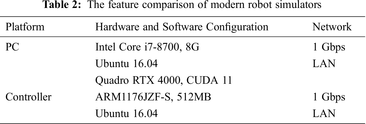
First, a regional network that is usually built in the factory was used. The relevant experimental configuration is described in Tab. 2. We tested the transmission method using our packet transmission and the general XML configuration, and then compared the average time from node to terminal transfer. The experimental results are shown in Fig. 9. From the left figure, we can see that our method of transmitting and processing data is about 2.5 times faster than the traditional method. With the increase of data transmission volume, the gap becomes more transparent. Second, we evaluated the efficiency of our semaphore method by continuing the aforementioned experimental platform. We changed the related machine data transmitted to the transfer database and accessed some shared values. If the semaphore is not used, the entrance of critical resources should be placed in the queue for processing. Then the experiment compared our method with the way of using the queue. From the right figure of Fig. 9, we can observe that the queue can only process one request at a time, but our method’s limitation can be adjusted according to the upper limit of the semaphore accessed by the resource. Thus, the result shows our method can save a lot of time when many requests in the critical resource at the same time.

Figure 9: The comparison of (Left) transmission time and (Right) processing time
For simulation technique and CPU-GPU coherence, we implemented collision detection on the simulation system to test the simulation’s speedup and detected whether there was an intersection between two objects. According to the analysis results, the most critical factor affecting efficiency is the simulation’s number of components.
First, we tested the difference in the simulation system’s speed before and after the parallelization of the calculation of the object movement, assuming that each component is the same and all carry out a series of identical actions. The experimental results are shown in Fig. 10. From the left figure, we find that when the number of components is small, the difference between the two is not large, but the gap increases sharply with the number rise. It should be noted that when the number of components exceeds 30 (exceeding the GPU load), the speed is decreased, but overall it is faster than the result of bit parallelization.

Figure 10: (Left) Motion calculation time and (Right) Collision detection time in the simulation
Next, we compared the collision detection time of the components between the parallel and non-parallel programs. In the experiment, we assumed that each element was the same and performed a series of identical actions and collision detection operations for each component. The experimental results are also shown on the right side of Fig. 10. It is clear that even when the number of units is small due to the vast resources required for collision calculation and simulation movement, there is already a gap of about three times, and the gap will increase sharply with the rise of the number of components. The experimental result reached the gap of 10 times when the number of components was equal to 30. But the result of the parallel operation also achieved 7231 milliseconds, which exceeded the scope of instant collision detection and will be improved in our future work.
With the increasing popularity of smart manufacturing, we discussed the importance of ubiquitous robotic simulation systems. In this paper, a general technique for real-time robotic simulation was proposed and proven suitable for manufacturing. According to the actual usage, the robot’s communication and simulation technique in this paper were developed into an independent model and can be applied to a compatible manufacturing environment.
We cut the manufacturing system model into separate blocks that serve as a test platform for our techniques and algorithms. The results showed that the communication and monitoring system could effectively enhance the interoperability between the robot and each component. Finally, through the simulation system, we can get most of the execution results and adjust them before the physical machine operates. We also deployed our model on Robot Operating System (ROS) and achieved a good performance because there are many types of research [15] of robot simulation bases on it in recent years.
Acknowledgement: The authors would like to thank the reviewers who provided insight and expertise that assisted in improving the research paper quality. Their comments improved the manuscript greatly. Finally, the Editor’s comment made us realize a huge alteration in the paper and improved its quality thoroughly. We appreciate the linguistic assistance provided by TopEdit (www.topeditsci.com) during the preparation of this manuscript.
Funding Statement: The authors received no specific funding for this study.
Conflicts of Interest: The authors declare that they have no conflicts of interest to report regarding the present study.
1. J. Lee, H. A. Kao and S. Yang, “Service innovation and smart analytics for industry 4.0 and big data environment,” Procedia CIRP, vol. 16, no. 1, pp. 3–8, 2014. [Google Scholar]
2. J. C. Zagal and R. D. S. Javier, “UCHILSIM: A dynamically and visually realistic simulator for the RoboCup four legged league,” in Proc. RSWC, Heidelberg, BER, Germany, pp. 34–35, 2004. [Google Scholar]
3. T. Zhukabayeva, Z. Oralbekova, M. Zhartybayeva, A. Zhumadillayeva and A. Adamova, “Prospects of development of technologies in the field of robotics and the stages of design of mobile robotic complex,” in Proc. ICITCS, Kuala Lumpur, KL, Malaysia, pp. 1–4, 2015. [Google Scholar]
4. J. Davis, T. Edgar, J. Porter, J. Bernaden and M. Sarli, “Smart manufacturing, manufacturing intelligence and demand dynamic performance,” Computers & Chemical Engineering, vol. 47, no. 1, pp. 145–156, 2012. [Google Scholar]
5. W. Wang, Q. Cao, X. Zhu and S. Liang, “A framework for intelligent service environments based on middleware and general purpose task planner,” in Proc. IE, Prague, CB, Czech Republic, pp. 184–187, 2015. [Google Scholar]
6. T. Tomić and S. Haddadin, “Simultaneous estimation of aerodynamic and contact forces in flying robots: Applications to metric wind estimation and collision detection,” in Proc. ICRA, Seattle, WA, USA, pp. 5290–5296, 2015. [Google Scholar]
7. H. Kitano, M. Asada, Y. Kuniyoshi, I. Noda and E. Osawa, “RoboCup: The robot world cup initiative,” in Proc. AAMAS, New York, NY, USA, pp. 340–347, 1997. [Google Scholar]
8. M. Asada, T. Balch, A. Bonarini, A. Bredenfeld, S. Gutmann et al., Middle size robot league rules and regulations for 2019.Montreal, QC, Canada: RoboCup, 2018. [Online]. Available: https://msl.robocup.org/wp-content/uploads/2018/12/Rulebook_MSL2019_v20.pdf. [Google Scholar]
9. C. Schlegel, “Communication patterns as key towards component-based robotics,” International Journal of Advanced Robotic Systems, vol. 3, no. 1, pp. 9, 2006. [Google Scholar]
10. E. Colgate, A. Bicchi, M. A. Peshkin, J. E. Colgate, B. Siciliano et al., Safety for physical human-robot interaction.Berlin, BL, Germany: Springer Handbook of Robotics, 2008. [Online]. Available: https://msl.robocup.org/wp-content/uploads/2018/12/Rulebook_MSL2019_v20.pdf. [Google Scholar]
11. A. D. Santis, B. Siciliano, A. D. Luca and A. Bicchi, “An atlas of physical human-robot interaction,” Mechanism and Machine Theory, vol. 43, no. 3, pp. 253–270, 2008. [Google Scholar]
12. J. Frémy, F. Michaud and M. Lauria, “Pushing a robot along—A natural interface for human-robot interaction,” in Proc. ICRA, Anchorage, AK, USA, pp. 3440–3445, 2010. [Google Scholar]
13. J. Vorndamme, M. Schappler and S. Haddadin, “Collision detection isolation and identification for humanoids,” in Proc. ICRA, Singapore: Sands Expo and Convention Centre, MBS, pp. 4754–4761, 2017. [Google Scholar]
14. F. Flacco, A. Paolillo and A. Kheddar, “Residual-based contacts estimation for humanoid robots,” in Proc. IEEE-RAS, Cancun, CUN, Mexico, pp. 409–415, 2016. [Google Scholar]
15. Z. Yan, L. Fabresse, J. Laval and N. Bouraqadi, “Building a ROS-based testbed for realistic multi-robot simulation: Taking the exploration as an example,” Robotics, vol. 6, no. 3, pp. 21, 2017. [Google Scholar]
 | This work is licensed under a Creative Commons Attribution 4.0 International License, which permits unrestricted use, distribution, and reproduction in any medium, provided the original work is properly cited. |