DOI:10.32604/iasc.2021.016077
| Intelligent Automation & Soft Computing DOI:10.32604/iasc.2021.016077 | |
| Article |
Research and Development of a Brain-Controlled Wheelchair for Paralyzed Patients
1Department of Electrical and Computer Engineering, North South University, Bashundhara, Dhaka, 1229, Bangladesh
2Department of Computer Science, College of Computers and Information Technology, Taif University, Taif, 21944, Saudi Arabia
3Department of Information Technology, College of Computers and Information Technology, Taif University, Taif, 21944, Saudi Arabia
*Corresponding Author: Mohammad Monirujjaman Khan. Email: monirujjaman.khan@northsouth.edu
Received: 22 December 2020; Accepted: 13 April 2021
Abstract: Smart wheelchairs play a significant role in supporting disabled people. Individuals with motor function impairments due to some disorders such as strokes or multiple sclerosis face frequent moving difficulties. Hence, they need constant support from an assistant. This paper presents a brain-controlled wheelchair model to assist disabled and paralyzed patients. The wheelchair is controlled by interpreting Electroencephalogram (EEG) signals, also known as brain waves. In the EEG technique, an electrode cap is positioned on the user’s scalp to receive EEG signals, which are detected and transformed by the Arduino microcontroller into motion commands, which drive the wheelchair. The proposed wheelchair is implemented using an Arduino-based robot controlled by a human brain wave using a Brain-Computer Interface (BCI). The human brain wave is captured using a low-cost Neurosky MindWave headset. The proposed wheelchair has the potential to have an immense effect on the healthcare industry. The use of this brain-controlled wheelchair can improve the quality of life of a paralyzed patient.
Keywords: Electroencephalography; brain computer interface; blink; Arduino; neurosky; wireless data; transfer; wheelchair; brain control; paralyzed patients
Paralysis is a medical condition that severely restricts the movement of a person. It typically happens because of a nervous system injury. Strokes (29%), spinal cord injuries (23%), and multiple sclerosis (17%) are the leading causes of paralysis [1,2]. Paralyzed people face many difficulties. About 16 million people in Bangladesh are paralyzed to some extent [3]. It is a major challenge to develop a technology that would provide maneuvering support to a fully paralyzed person [4]. Smart wheelchairs may assist disabled people in maneuvering. Maneuvering support is essential to make them independent. It also reduces the required care from family members. Smart wheelchairs integrate with a range of humanoid computer interface technologies, such as speech, head motion, Electromyography (EMG), wrist motion, and EEG, in addition to self-directed course-plotting, obstacle escaping, and additional features. In the past, many solutions have been proposed for disabled people to communicate with physical devices, such as arm EMG, the recognition of finger movements, and voice control. Most of them, however, depends on muscles, body motions, or speech commands. These acts are not easy for paralyzed individuals to execute [5–9].
Less than 5% of power wheelchair users use very advanced control mechanisms such as eye contact or tongue pad interfaces (perhaps as few as 1%) [10]. Madrasas et al. [11] suggested one of the primary illustrations of independent wheelchairs, fitting a wheelchair with a visualization system and utilizing sonar to locate paths and correct the wheelchair’s direction in hallways. Another solution with NavChair was proposed by Levine et al. [12], a power-driven wheelchair outfitted with an obstacle escaping procedure and several methods to monitor movements over entranceways or prevent wall collisions. Monte-sano et al. [13] proposed an independent wheelchair for children with cerebral disabilities, having complicated steering states to assist in tight entranceways and occupied or messy situations. The Vector Field Histogram (VFH) approach was formerly established to avoid obstacles by robots and was later ported to the wheelchair [14]. The NavChair has a navigation structure planned to sidestep obstacles, track walls, and enable movement without risk. For the self-localization of a motorized wheelchair, current ceiling lights in an enclosed setting are used as mapping symbols. Therefore, the chair is limited to one house, whose arrangement is encoded in the development of the wheelchair. “Wellesley” is the name given by Holly Yanco, first at Wellesley College and now at Massachusetts Institute of Technology (MIT), to the chair used for investigational progress [15]. This chair has an integral method to its success that is close to a subsumption architecture, a control architecture that couples sensory information to action selection. Using a graphical interface, the chair user points in the direction in which the chair should head. The problems discussed in other studies [12–15] can be overcome by designing a special wheelchair controlled by a person’s brain waves to move voluntarily. Different states of the brain are the product of various nervous activity patterns. These patterns drive waves categorized by their amplitudes and frequencies, such as beta waves—concentration-related waves between 12 Hz and 30 Hz. In contrast, alpha waves, between 8 Hz and 12 Hz, are linked to a calm mental position [16].
In this paper, a low-cost brain-controlled wheelchair for paralyzed patients is developed and tested. This is an Arduino-based wheelchair that is operated using the BCI technique of interpreting human brain waves. This approach is typical due to its low cost. The human brain wave signals can be obtained with an affordable Neurosky MindWave headset. Eye blinking is used to control the robot, as eye blinks typically trigger a large pulse in the EEG signal. The operator can direct the command to steer the machine by blinking twice in a short time, with a neural network being used to identify the blinking signal. By moving in various locations, the robot will test whether it can track the intended course, avoid obstacles, and stop in a particular location. This remaining portion of the article is structured as follows. Methods and materials are discussed in Section 2, and Section 3 explains the system implementation. The system design is defined in Section 4, and the final prototype is described in Section 5. Results, tests, and optimization are discussed in Section 6, and in Section 7, conclusion is provided for the presented work.
This section discusses the technical aspects of the proposed wheelchair.
2.1.1 System Level Technical Design
The wheelchair is limited to a maximum speed of 5 Miles Per Hour (MPH). The battery-operated life expectancy is three to four hours before recharging is required. It is easy to replace all the necessary parts, making the wheelchair sustainable. The chair has user-fit adjustable restraints and helps the user to remain anchored in his or her chair. The chair has a foot support with heel support and a belt to guarantee that the user’s feet remain safe. There are soft cushions to preserve the user’s comfort in the chair. The system produces an electrical signal following an eye blink. This signal is routed to the microcontroller, which processes it and gives the speed controller a Pulse Width Modulation (PWM) signal. This speed controller quickly switches on and off, which effectively powers the motor for a measured period depending on the service cycle. The electrical signal is then converted to mechanical operation. While reducing the Revolutions Per Minute (RPM), the transmission can work to intensify the torque. This intensified torque works to rotate the wheels of the chair.
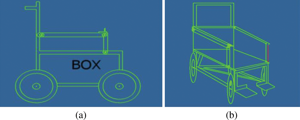
Figure 1: Wheelchair design (a) Chair design (side view) (b) Chair design (front view)
As shown in Fig. 1, the frame verifies that the rear and front are equally well-adjusted. The engines are connected to the front axles, and a control box is connected below the seat. The main computing unit has the main electrical components: battery, microchip, PWM, and motor. The front wheels are attached to the motor by the chain. The rear wheels move freely and can move in any direction. The Arduino microcontroller is attached beside the mainboard for easy maintenance. Figs. 1(a) and 1(b) show the side view’s chair design and front view, respectively.
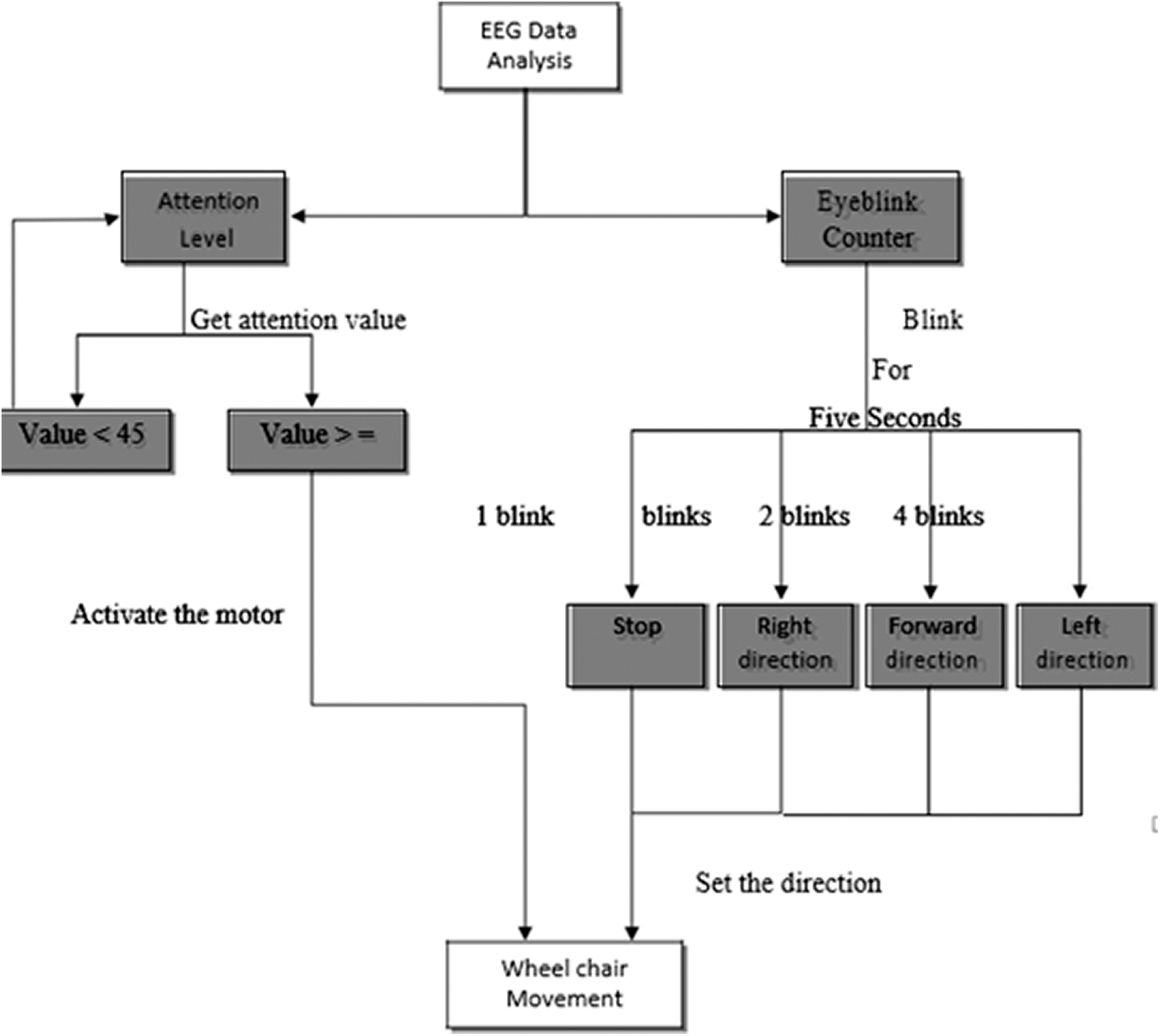
Figure 2: Complete system block diagram
2.1.3 System Classification of the Wheelchair
The primary control of the wheelchair is done by brain signal and eye blink. The user must be fully conscious. Otherwise, he or she cannot use the wheelchair safely. The motor of the wheelchair is activated when the user’s brain activity reaches a certain point. Patients may imagine on the right hand or left-hand activity, focus on something or doing math, etc., and increase the attention or focus level that triggers the motor. To set the direction, the user must perform a blink sequence to specify the desired direction. The wheelchair also has a joystick controller so that the user may operate it on their own even when the receiver of the brain signal is not in operation. This requires careful configuration of the chair’s joystick. The battery must last three to four hours to allow people to use the chair on brief trips to homes or the mall, for instance. Such visits often require the chair to be compact enough to fit into a doorway of the normal height.
Fig. 2 demonstrates a complete working process diagram.
This section presents the architecture of the software and the code. The Arduino microcontroller performs the main processing of the data. Initially, the brain signal receiver interprets the raw EEG data using different channels. The data are passed to the Arduino through the Bluetooth module. The device used to record brain signals is the Neurosky MindWave Mobile 2. It has eight channels to record and analyze different types of brain signals, for example, brain waves like alpha, beta, gamma, and raw EEG.
Eyeblink detection is essential to control the movement of the wheelchair. The number of eye blinks determines the direction of the wheelchair. The eye blink is detected using a sensor attached above the eyebrows. When a person blinks, the skin of the forehead contracts. If the person gives a pressure blink, the muscle gets more contracted, sensed by the Neurosky sensor. A major challenge was to distinguish the pressure blink from the regular eye blink. A blink strength ranging between 0 and 100 is used in this study. When a person gives a regular eye blink, the strength stays below 21. However, when a person gives a pressure blink, it gives the output between 50 and 51. The program is developed to count those blinks where the strength value is 50 to 51 as a blink counter.
2.2.2 Attention and Level Detection
Attention level is calculated by measuring the attention/focus level of the user every second. When a patient focuses on something, their attention level rises. If a fully paralyzed patient imagines his or her left or right arm movement, his or her brain starts generating different types of brain waves. Similar focus-related activity occurs in all human brains. The sensor receives those waves and analyzes those data using different channels. The patient’s attention level increases when he or she keeps on focusing on something. The range is set between 0 and 100 to measure this level. Usually, this attention level stays below 40 when the user is relaxing and doing nothing. This level can rise to 95 according to the amount of concentration they dedicate to a mental task. In this project, the key-value required to power up the motor is above 45. Arduino code is used to process the whole data and send appropriate signals to the motor controller circuit. The attention level detection and blink detection are done in parallel. To record the eye blink, a five-second time delay is used. Following this delay, each user’s eye blinks are eligible to trigger an eye blink event. For the next five seconds, the system counts every blink and sums them up. That value is transferred into the primary blink variable, which is used to operate the wheelchair. After five seconds, the blink counter value is zeroed out, and the system awaits the next blink. Simultaneously, the brain wave range is also generated by measuring the users’ focus level.
2.3 Essential Parts of the Devices
Micro-controller (Arduino UNO): The Arduino Uno is an ATmega328P-based microcontroller board used in this framework. Fig. 3 shows the Arduino Uno. It has a 16 MHz quartz crystal, a Universal Serial Bus (USB) connection, 14 digital input/output pins, 6 analog inputs, a power jack, and a reset button [17].
Light Emitting Diode (LED): There is an in-built LED operated by digital pin 13. The LED is on when the pin is HIGH value, and it is off when the pin is LOW.
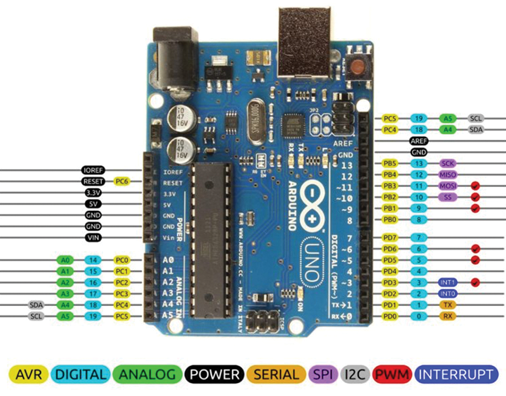
Figure 3: Arduino Uno [17]
Voltage Input (VIN): The Arduino/Genuino board’s input voltage when the external power source is used (as opposed to 5 volts when the USB or other regulated power source is connected). Via this pin, it can be supply voltage or access via this pin while supplying voltage through the power jack [17].
5 Volt (V): From the regulator on the board, this pin outputs a controlled 5 V. It is possible to drive the board from either the Direct Current (DC) power jack (7–20 V), the USB connector (5 V), or the VIN pin (7–20 V) of the board. The supply of voltage through the 5 V or 3.3 V pins bypasses the regulator, and the board can be impaired [17].
3V3: The onboard regulator produces a 3.3 V supply. The overall drawing current is 50 Milliamperes (mA) [17].
GND: Ground pins [17].
IOREF: This pin gives the voltage reference that the microcontroller works with the Arduino/Genuino board. The IOREF pin voltage is read by a correctly built shield and chooses the required power source or requires 5 V or 3.3 V to work with the voltage translators on the outputs [17].
Reset: Usually, a reset button is applied to shields that block the one on the board [17].
Two modules (BCI System and Data Processing) comprise the proposed EEG-based brain-controlled robotic wheelchair.
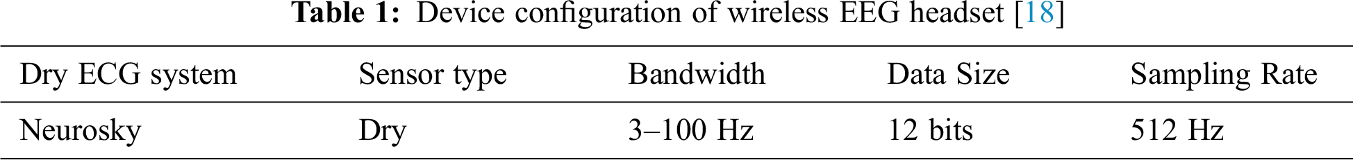
Bio-sensing knowledge plays a critical part in health maintenance. The EEG receiving headset contains a dry, single-channel biosensor used to measure EEG and EMG (attention and eye blink) signals situated on the frontal lobe of the FP1. Data on the wireless EEG receiver requirements are given in Tab. 1.
By conducting Fast Fourier Transform (FFT) analysis, the artifacts and noise generated in the device can be removed. Using the Level Analyzer method, the Attention13 and the blinking signal levels are extracted. This module transmits the output signals to the wheelchair. The Mind wave headset is a small, matte plastic product in black/light blue that fits comfortably over the left ear. The main sensor sits securely on the forehead, but changing it takes some time for a first-time user. The ear pin is convenient as well, and the entire device has the bonus of permitting one to wear over-ear headphones simultaneously if desired. It attaches to Android or iOS mobile devices through Bluetooth and operates with up-to-date systems. With one single AAA battery, its battery-operated life is estimated at seven to nine hours.
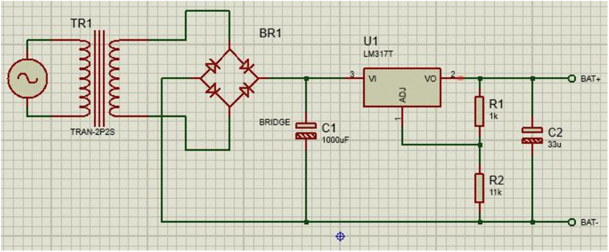
Figure 4: Charging circuit diagram
• Implements a brain-computer interface.
• A working mobile device for Android and iOS as well as Personal Computer (PC) & Mac.
• Headset securely calculates and interprets the EEG power varieties, attention or meditation, and eye blinks.
• Sensor rests on the forehead directly above the eye and is grounded via an ear clip (FP1 position)
• Uses a MindWave Mobile for data acquisition
• TGAM1 module is used
• Programmed wireless pairing
• Requires only one AAA Battery
• Battery life cycle of 8+ hours
• Bluetooth v. 3.0 embedded
• Unique Headset Identification (ID), in order to use multiple devices simultaneously without having pairing issues.
• Supports both Android and IOS
The charging circuit is built along with the main control circuit. This inbuilt circuit helps to charge the 12 V battery quickly and efficiently. The battery is not necessary to remove for charging as the circuit is fitted with the chair. This charger is small, portable, and very cheap. Very few components and a simple design have been used to build the circuit. The charger can charge the battery up to 100% taking only three to four hours. The circuit design is shown in Fig. 4.
2.3.7 Metal-Oxide-Semiconductor Field-Effect Transistor (MOSFET)
The MOSFET is like a voltage regulating switch. To be more specific, when the gate-to-source voltage is negative, an N-channel amplification style MOSFET presents an infinite resistance, which transforms into a minimal resistance when the gate-to-source voltage is a few volts positive.
A buck converter is a simple circuit. The high-side MOSFET switches on and off. A control Integrated Circuit (IC), not pictured, utilizes a closed feedback loop to control the output voltage. The DC transfer function links the input voltage, output voltage, and duty cycle of the buck converter. The output voltage is Vout, the input voltage is Vin, and the service cycle (the measure of time the MOSFET is active) is D, where Vout = Vin * D. The inductor and capacitor create a low pass filter. The MOSFET switching operation is smoothed out by this low pass filter and generates a suitable, smooth DC voltage.
A three-terminal positive regulator with a 12 V fixed output voltage was used as the basic L7805 voltage regulator. This fixed regulator provides a local regulation, inner current restriction, thermal shutdown control, and safety. A max current of 1.5 A can be provided by each one of these voltage regulators. The voltage regulator reduces the 12 V supply to 5 V from the Arduino Vin pin, which is then used to bias the IC of the L293D motor driver. To ensure that the device has a consistent reference voltage level, pins 12 and 13 of the motor drivers are linked with the Arduino to a common ground. Pins 11 and 14 provide the DC motor with the output signal, while pins 10 and 15 provide the Arduino motor driver with the data signals used to select whether the motor is clockwise or anti-clockwise spinning.
An optocoupler (also referred to as an opto-isolator, picture coupler, or optical insulator) is an electrical element that uses light to conduct electrical signals among two isolated circuits. The basic architecture of an optocoupler comprises an infrared light-producing LED, and a photosensitive semiconductor chip used to detect the infrared beam emitted. An optocoupler contains a light emitter, an LED, and a light-sensitive receiver, typically of simple configuration and sometimes consisting of only one photo-diode, photo-resistor, photo-SCR, photo-transistor, or photo-TRIAC. Optocouplers may be used unaccompanied or with various other electronic devices, such as transistors and TRIACS, to deliver the compulsory electrical separation for a lower voltage controller signal. Microprocessor input/output switching, DC and AC power control, PC communications, signal isolation, and power supply regulation suffers from current ground loops. These are popular applications for optocouplers. The electrical signal is transmitted may be either analog (linear transduction) or digital (discrete pulses) [19].
Fig. 5 shows the control circuit to process the signal and control the wheelchair.
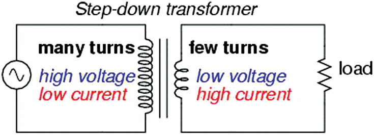
Figure 5: Step-down transformer [20]
Without moving parts, transformers can convert Alternating Current (AC) voltage and current levels at very high efficiencies, allowing the widespread delivery and use of electric power. Fig. 6 shows the step-down transformer.
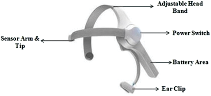
Figure 6: Neurosky mind wave dry signal receiver [21]
A diode bridge is a circuit consisting of four diodes in a bridge configuration, supplying the identical output polarity for any input polarity. It is acknowledged as a bridge rectifier for converting an alternating current input into a direct current output.
Fig. 6 shows the Neurosky MindWave dry signal receiver.
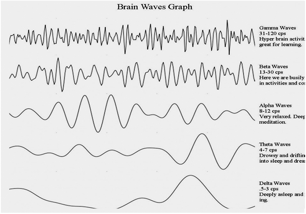
Figure 7: Graph of brain wave [27]
Tab. 1 shows the information on the wireless EEG headset’s specifications, as seen in the previous section. Signal processing can be carried out in a module for data processing. Neurosky pre-processes the detected signals and transfers them to the PC. Using the level analyzer method, the focus and blinking signal levels are separated. Signals from the output are transmitted to the wheelchair.
The acquisition of EEG signals is mainly achieved by engaging electrodes on the scalp. Some use five-channel bipolar electrodes, while some others use 12 Ag/Cl electrodes. Fig. 7 shows a graph of EEG brain waves. Simpler commercial BCI methods with one electrode and a reference electrode on the ear are also used [22]. Signals are acquired by placing the electrode over a particular location of the brain. EEG data read from electrodes contain lots of noise, so eliminating noise in the recorded EEG pre-processing step is required [23,24]. The most commonly used pre-processing step is filtering the EEG. Common Spatial Pattern (CSP) and Principal Component Analysis (PCA) are also used to reduce the signal-to-noise ratio. Threshold-based noise rejection and Common Average Reference (CAR) of multiple electrodes can also reduce the signal-to-noise ratio. Two dry sensors are used to distinguish and filter the EEG signals. The tip of the sensor detects electric signals from the forehead. When collecting the EEG signal, the device also collects the ambient electric field formed by the muscles of the subject, nearby machines, electrical sockets, light bulbs, and additional electrical devices—the so-called electrical sound. The second sensor, the ear clip, is both a source and a controller, which permits the electrical sound [25,26] to be filtered by the Think Gear chip. Think Gear is the technology inside every NeuroSky product or partner product that enables a device to interface with the wearers’ brainwaves. The computer checks the power spectrum of the raw signal (alpha, beta, delta, gamma, theta), level of focus, level of mediation, and blink detection. The raw data from the EEG are obtained at a rate of 512 Hz. Every second, other measurable values are generated. The key source is raw EEG data. Fig. 8 shows a graph of a brain wave. The figure indicates the stages of attenuation and mediation. EEG rhythmic activity frequency bands are described in Tab. 2.
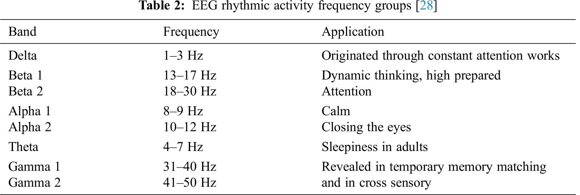
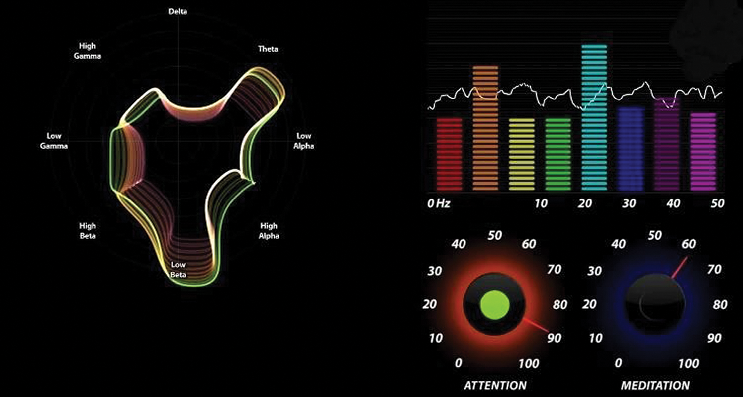
Figure 8: Attention and meditation level
BCI-controlled wheelchairs can be classified into two categories: automatic control and subject control. One category makes use of the direct control technique to maneuver the wheelchair using EEG signals from the brain. In the direct control technique, usually, a subject is asked to perform mental imagination. The EEG signal is obtained while the user is performing the task mentioned above. The output of the signal is used as a direct command to steer the wheelchair. A user can switch between automatic control and subject control. In automatic control, the intelligent system takes care of obstacle avoidance, and in subject control, the user takes care of navigating the wheelchair. For control over movement direction, blink strength is recorded. The direction is set according to predefined blink sequences, such as three blinks for the left direction and four blinks for the right direction. An ultrasonic sensor is implemented for obstacle avoidance. The wheelchair is powered by a 24 V/45 A rechargeable battery, which provides a two-hour drive time to the wheelchair.
The robotic wheelchair consists of an Arduino microcontroller that regulates the wheelchair’s motion by capturing the given order. The wheelchair concept model with the above requirements is intended for the assessment of the working model. The brain signal receiver is connected with the Arduino through the Bluetooth module. The program running on the microcontroller analyzes the signal. Initially, there is noise. Later the signal is processed, and the noise is reduced. The microcontroller’s output will be provided to a motor driver, which can then be used for turning the motor on and off. A blink sequence is recorded to steer the wheelchair. For left and right steering, a certain blink sequence is required. If the motor gets a signal to turn on, it will be activated for five seconds. Then the user needs to perform the blink and attention sequence to start the motor again. This feature is for the safety and better performance of the wheelchair. Whenever the user needs to move forward or in any direction, the motors need to be activated. A flow chart of the system design is shown in Fig. 9. To activate the motors, the user must blink twice or more. Then the sensor will start receiving the signals. The human brain produces very unstable waves. This blink activation system is implemented to prevent unintentional movement. To set the direction, the user must use a pressure blink.
A complete circuit diagram of the wheelchair is depicted in Fig. 10.
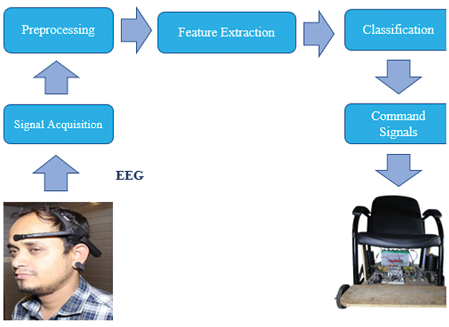
Figure 9: A flow chart block diagram of the proposed brain control wheelchair system design
A complete circuit diagram of the wheelchair is depicted in Fig. 10.
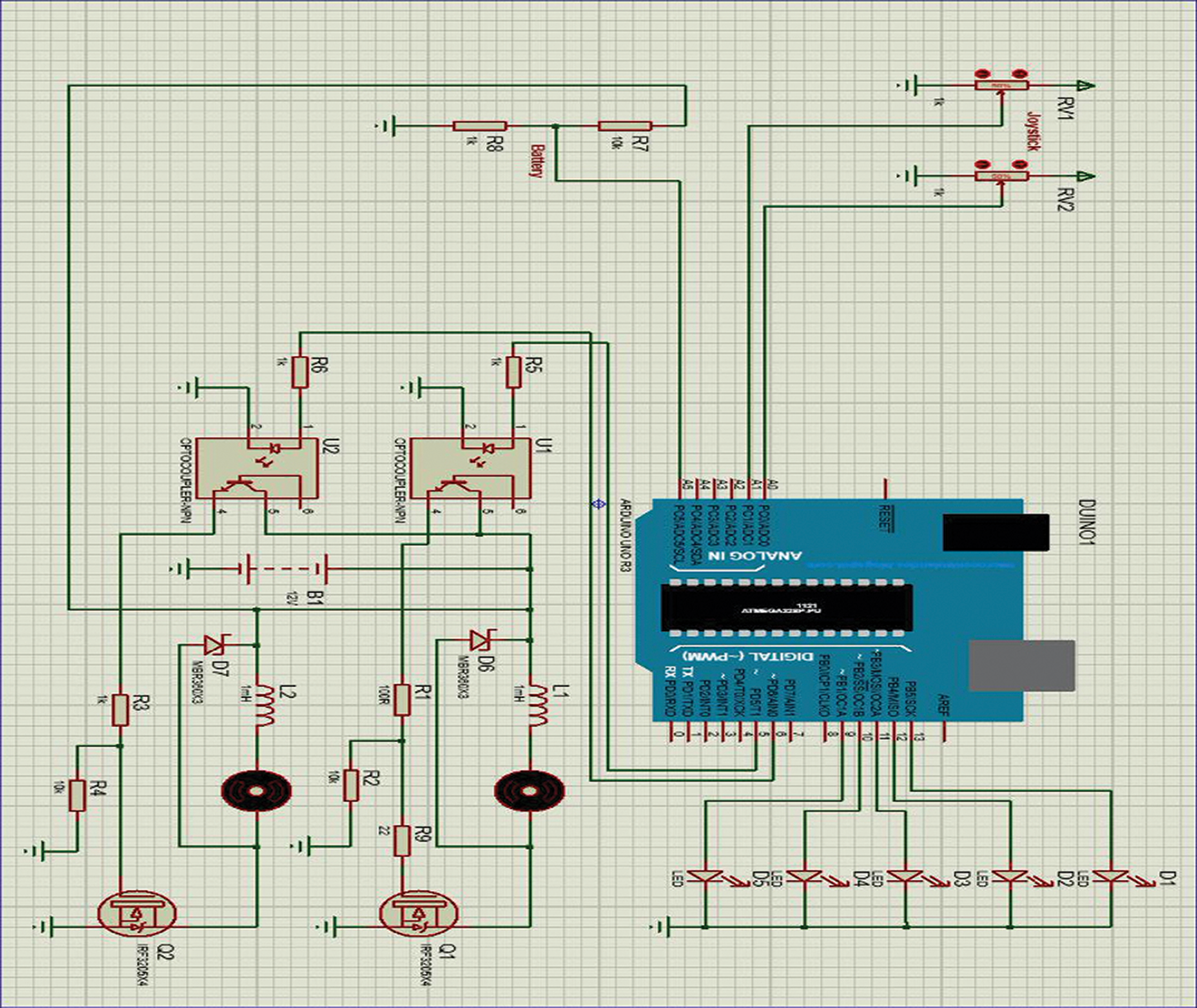
Figure 10: Complete circuit diagram of the electric wheelchair
The final prototype of the brain control wheelchair is presented in Fig. 11. It shows a complete wheelchair equipped with two gear motors, a control circuit, a 12 V battery, a gear motor, and an Arduino. The prototype is fully functional using a brain signal receiver. Some modifications are done to optimize the performance of the wheelchair.
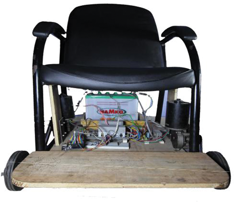
Figure 11: Final prototype of the brain control wheelchair
Fig. 12 shows the control circuit to process the signal and control the wheelchair. The charging circuit consists of a one-step down transformer and some other assistive devices. First, the Alternating Current (AC) mains (220 V) is stepped down to 12 V AC. Then bridge rectifier is used with four diodes and then using a capacitor of 2200 Microfarad (μF). It produces around 15–17 V DC. A series voltage regulator LM317 is used with a tuned output of 14.6 V. It is important to note that a large heat sink needs to be used to keep the regulator cool. There are LEDs for indication purposes only, indicating whether the chair is on or off.
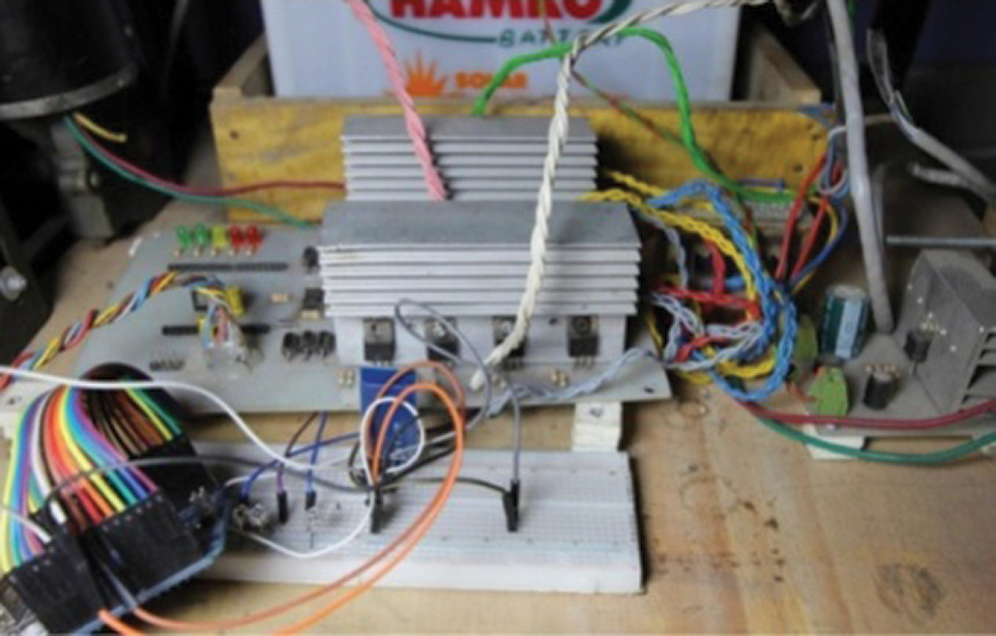
Figure 12: Control circuit to process the signal and control the wheelchair
6 Results, Tests, and Optimization
The EEG signal acquisition is mainly achieved by putting the headband on the scalp and holding the device’s switch. Fig. 13 suggests a brain sensor on the head of the consumer. It captures alpha, beta, and muscle capacity. The data are obtained by the device and are then transmitted to the Neurosky MindWave application through a Bluetooth system, such as a smartphone or tablet. It takes around 50 s to send the data to the control circuit to start up the motor after processing the data signal. The charged wheelchair can be used for six hours in total and needs to be recharged after that period.
The EEG signals are monitored to determine if the attention level is greater than 50. If it is, then an interrupt is sent to start the wheelchair. The strength of the blink level has to be more than 15 for movement operations. The movement operations are given as follows: following two blinks, the chair moves forward; following three blinks, the chair moves to the right; following four blinks, the chair moves to the left; and following a single blink, the chair stops. Users should avoid storing or using wheelchairs in the vicinity of open flames or fuel items resulting in significant property damage or injury. In a rainstorm, users should also not leave power wheelchairs or stock them in a moist zone for a lengthy period. It must ensure that the battery pack/box is tightly fastened at all times. The battery must be recharged after each use, and it must be checked that the off/on switch on the control stick is in the OFF situation before conducting any repair, modification, or operation.
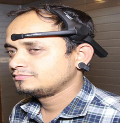
Figure 13: Brain sensor on the user’s head
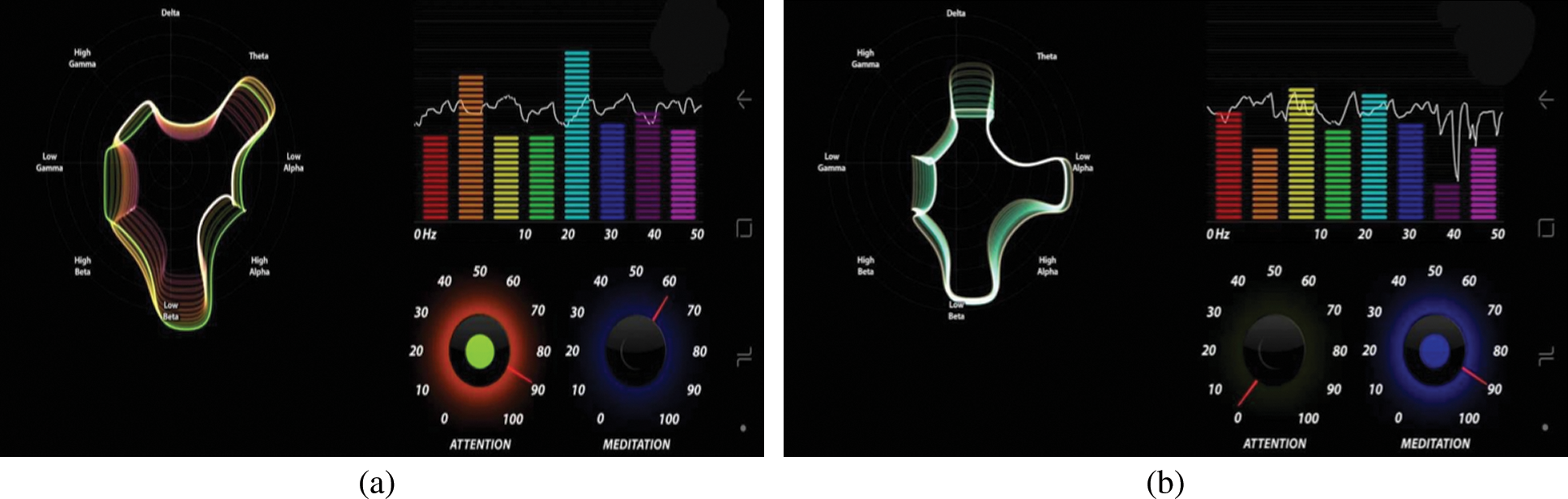
Figure 14: (a) High attention level when deeply focusing on something (instantaneous data), (b) Low attention level while relaxing (real-time data)
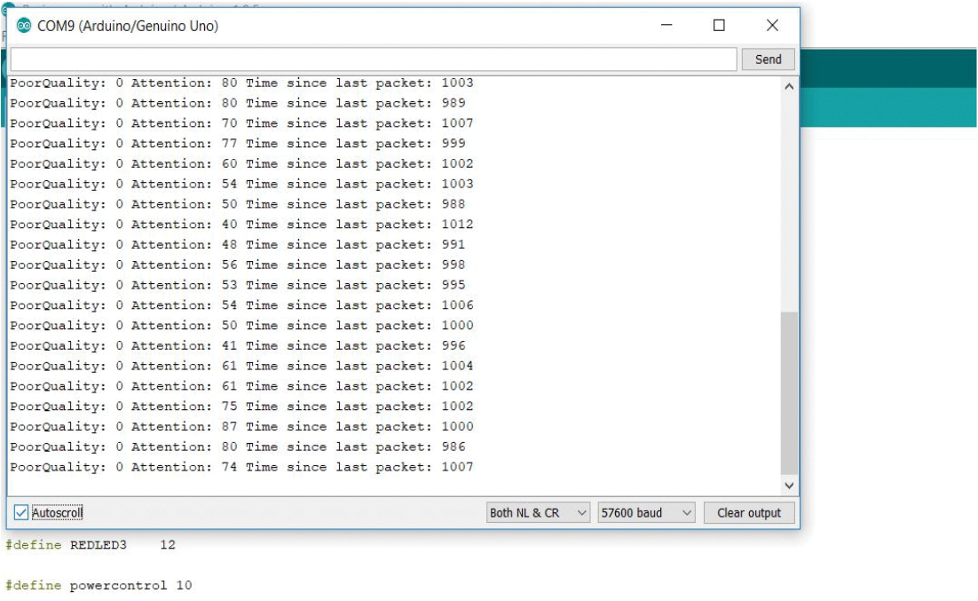
Figure 15: Real-time attention level data collected from Arduino serial monitor
The first test was conducted with a brain signal. The EEG sensor was placed on the user’s head. Then the sensor was connected to Arduino through the Bluetooth module. Code was written and implemented in the Arduino to prevent the eye blink counter from resetting. After powering up the Arduino and connecting with the laptop, the brain signal was tested. When the user is giving attention to some object or focusing on anything, or doing math or any brainstorming activity, the attention level increases. The average attention level while focusing on something was 55–70. When a user is relaxed the output, the value decreases to 0–40. Fig. 14 shows different attention value that changes according to the user’s focus. Fig. 14a shows a high attention level when deeply focusing on something (real data). Fig. 14b shows a low attention level while relaxing (real data). Real-time attention level data collected from the Arduino serial monitor is illustrated in Fig. 15.
The sensor was mounted on the left side of the forehead to test eye blinks. Then a different type of eye blink was given to verify the output. First, a regular eye blink was given as input. The strength of regular eye blink, according to our program, was 26 out of 100. Then a pressure eye blink was given as input, which corresponded to an output of 51 out of 100. For different blink pressures, the outputs were different.
The wheelchair movement in different directions was tested with a joystick first. The main processing unit, which is an Arduino, was connected to the wheelchair control circuit. The brain signal receiver was used to test the final prototype.
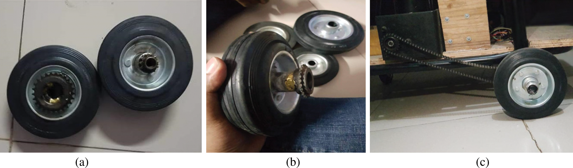
Figure 16: (a) Larger wheel with large chain pinion is attached, (b) Larger wheel with large chain pinion are attached (side view) and (c) Wheel assembly with the motor
Another counter variable is used to prevent the eye blink counter from resetting. The counter variable was set in a loop so that whenever a blink occurred, the temporary blink counter value is added with the main blink counter. This main blink counter does not change when the attention level gets updated every second. Every three seconds, the main blink counter is reset to zero to count the user’s next instruction.
6.2.2 Wheel Chair Speed Improvement
The wheelchair speed was initially very slow. In order to increase the speed, the existing wheels were replaced by larger wheels. The previous wheel mount was too small for the large wheels, but changing the mount was not efficient. In order to solve the problem, a larger wheel mount was attached to the smaller mount. The rear wheel was also balanced for the smoother movement of the wheelchair. After the modification, the position of the chair was balanced relative to the ground. The larger wheel in the rear and balanced chair position equalized the load on every wheel, which provided a smoother and more comfortable ride to the user. Fig. 16a shows a larger wheel attaching to a large chain pinion. Fig. 16b shows a larger wheel attaching to a large chain pinion from a side view. Fig. 16c shows the wheel assembly with the motor. Testing and optimization have been discussed in this section. After checking and independently refining this system, it is noted that the system works perfectly. This refinement implies that we have essentially introduced the prototype of the entire framework that we initially conceptualized.
This paper presents a prototype of a smart brain-controlled wheelchair for paralyzed patients. The prototype of the wheelchair has been implemented using NeuroSky technology. This proposed wheelchair will potentially have an immense effect on the healthcare industry and the lives of disabled people. Some extra features can be added in the future to improve the functionality and practicality of the wheelchair. Obstacle detection using an ultrasonic sensor can be implemented. A patient health monitoring system can also be added to the wheelchair. If an emergency occurs, a notification will be sent to those responsible for the patient. Real-time Internet of Things (IoT)-based patient monitoring devices can be integrated with the wheelchair to monitor the user’s physiological parameters such as heart rate device, Spo2 level, ECG, and temperature. A provision to send Short Message Service (SMS) alerts can be added for guardians in case of wheelchair malfunctions due to mechanical problems or accidents.
Acknowledgement: The authors would like to thank the Department of Electrical and Computer Engineering of North South University and Taif University Researchers Supporting Project number (TURSP-2020/98), Taif University, Taif, Saudi Arabia. We also thank LetPub (www.letpub.com) for its linguistic assistance during the preparation of this manuscript.
Funding Statement: Taif University Researchers Supporting Project number (TURSP-2020/98).
Conflicts of Interest: The authors declare that they have no conflicts of interest to report regarding the present study.
1. R. Madarasz, L. Heiny, R. Cromp and N. Mazur, “The design of an autonomous vehicle for the disabled,” IEEE Journal of Robotics and Automation, vol. 2, no. 3, pp. 117–126, 1986. [Google Scholar]
2. World Health Organization, Neurological disorders public health challenges, 2006. [Online]. Available: https://www.who.int/mental_health/neurology/neurological_disorders_report_web.pdf. [Google Scholar]
3. Wikipedia, Disability in Bangladesh, 2016. [Online]. Available: https://en.wikipedia.org/wiki/Disability_in_Bangladesh. [Google Scholar]
4. National Organization for Rare Disorders (NORDLocked in Syndrome, 2018[Online]. Available:https://rarediseases.org/rare-diseases/locked-in-syndrome/. [Google Scholar]
5. X. Perrin, F. Colas, C. Pradalier, R. Siegwart, R. Chavarriaga et al., “Learning user habits for semi-autonomous navigation using low throughput interfaces,” in IEEE Int. Conf. on Systems, Man, and Cybernetics, Anchorage, AK, USA, pp. 1–6, 2011. [Google Scholar]
6. S. Lee, Y. Shin, S. Woo, K. Kim and H. N. Lee, “Review of wireless brain-computer interface systems,” in Brain-Computer Interface Systems: Recent Progress and Future Prospects. London, UK: IntechOpen Limited, pp. 215–238, 2013. [Google Scholar]
7. B. Fischl, D. H. Salat, E. Busa, M. Albert, M. Dieterich et al., “Whole brain segmentation: Automated labeling of neuro anatomical structures in the human brain,” Neuron, vol. 33, no. 3, pp. 341–355, 2002. [Google Scholar]
8. R. Mahendran, “EMG signal-based control of an intelligent wheelchair,” in IEEE Int. Conf. on Communications and Signal Processing, India, pp. 1267–1272, 2014. [Google Scholar]
9. Kaur M., Ahmed P. and Qasim Rafiq M., “Technology development for unblessed people using BCI: Survey,” International Journal of Computer Applications, vol. 40, no. 1, pp. 18–24, 2012. [Google Scholar]
10. A. Butt and M. Stanacevic, “Implementation of mind control robot systems,” in IEEE Long Island Systems, Applications and Technology (LISAT) Conf., Farmingdale, NY, pp. 1–6, 2014. [Google Scholar]
11. R. Madarasz, L. Heiny, R. Cromp and N. Mazur, “The design of an autonomous vehicle for the disabled,” IEEE Journal of Robotics and Automation, vol. 2, no. 3, pp. 117–126, 1986. [Google Scholar]
12. S. P. Levine, D. A. Bell, L. A. Jaros, R. C. Simpson, Y. Koren et al., “The NavChair assistive wheelchair navigation system,” IEEE Transactions on Rehabilitation Engineering, vol. 7, no. 4, pp. 443–451, 1999. [Google Scholar]
13. L. Montesano, J. Minguez, J. M. Alcubierre and L. Montano, “Towards the adaptation of a robotic wheelchair for cognitive disabled children,” in IEEE/RSJ Int. Conf. on Intelligent Robots and Systems, Beijing, China, pp. 710–716, 2006. [Google Scholar]
14. D. A. Bell, S. P. Levine, Y. Koren, L. A. Jaros and J. Borenstein, “Design criteria for obstacle avoidance in a shared-control system,” in RESNA Annual Conf., Nashville, USA, pp. 1–3, 1994. [Google Scholar]
15. H. A. Yanco, A. Hazel, A. Peacock, S. Smith and H. Wintermute, “Initial report on Wellesley: A robotic wheelchair system,” in Proceedings of the Workshop on Developing AI Applications for the Disabled held at the Int. Joint Conf. on Artificial Intelligence, Montreal, Canada, pp. 1–5, 1995. [Google Scholar]
16. A. Jabbar and M. H. S. Khiyal, “Brain study analyzer using handwriting (BASH),” International Journal of Computer Applications, vol. 123, no. 12, pp. 50–54, 2015. [Google Scholar]
17. Make2explore, Overviewof Arduino Uno hardware-2, 2018. [Online]. Available: https://blog.make2explore.com/overview-of-arduino-uno-hardware-2/. [Google Scholar]
18. NeuroSky, NeuroSky SDK for NET: Development guide and API reference, 2006. [Online]. Available: http://developer.neurosky.com/docs/doku.php?id=hinkgear.net_sdk_dev_guide_and_api_reference. [Google Scholar]
19. Components 101, What is optocoupler and how it works?, 2019. [Online]. Available: https://components101.com/articles/what-is-optocoupler-and-how-it-works. [Google Scholar]
20. Printerest, Step-up and step-down transformers, 2020. [Online]. Available: https://www.pinterest.com/pin/502292164684711275/sent/?invite_code=0ba93ec1c7e8498e8af99a6659ca1d42&sender=21392304388500865&sfo=1. [Google Scholar]
21. NeuroSky Support Site, Mind wave diagram, 2016. [Online]. Available: http://support.neurosky.com/kb/mindwave/mindwave-diagram. [Google Scholar]
22. G. Pires, N. Honorio, C. Lopes, U. Nunes and A. T. Almeida, “Autonomous wheelchair for disabled people,” in ISIE ’97 Proc. of the IEEE Int. Sym. on Industrial Electronics, Guimaraes, Portugal, pp. 797–801, 1997. [Google Scholar]
23. T. Carlson and Y. Demiris, “Human-wheelchair collaboration through prediction of intention and adaptive assistance,” in IEEE Int. Conf. on Robotics and Automation, Pasadena, CA, USA, pp. 3926–3931, 2008. [Google Scholar]
24. J. Long, Y. Li, H. Wang, T. Yu, J. Pan et al., “A hybrid brain computer interface to control the direction and speed of a simulated or real wheelchair,” IEEE Transactions on Neural Systems and Rehabilitation Engineering, vol. 20, no. 5, pp. 720–729, 2012. [Google Scholar]
25. K. Arshak, D. Buckley and K. Kaneswaran, “Review of assistive devices for electric powered wheelchairs navigation,” ITB Journal, vol. 7, no. 1, pp. 13–23, 2006. [Google Scholar]
26. NeuroSky Mind Set, Instruction manual, 2009. [Online]. Available: http://download.neurosky.com/support_page_files/MindSet/docs/mindset_instruction_manual.pdf. [Google Scholar]
27. A. Jabbar and M. H. S. Khiyal, “Brain study analyzer using handwriting (BASH),” International Journal of Computer Applications, vol. 123, no. 12, pp. 50–54, 2015. [Google Scholar]
28. NeuroSky, BrainWave signal (EEG) of NeuroSky, 2009. [Online]. Available at: http://download.neurosky.com/docs/papers/eeg/NSKeeg.p. [Google Scholar]
 | This work is licensed under a Creative Commons Attribution 4.0 International License, which permits unrestricted use, distribution, and reproduction in any medium, provided the original work is properly cited. |