DOI:10.32604/iasc.2021.019024
| Intelligent Automation & Soft Computing DOI:10.32604/iasc.2021.019024 | |
| Article |
A Multi-Objective Secure Optimal VM Placement in Energy-Efficient Server of Cloud Computing
Department of Information Technology, Sri Venkateswara College of Engineering, Sriperumbudur, 602117, India
*Corresponding Author: Sangeetha Ganesan. Email: gsangeethakarthik@gmail.com
Received: 30 March 2021; Accepted: 01 May 2021
Abstract: Cloud Computing has been economically famous for sharing the resources of third-party applications. There may be an increase in the exploitation of the prevailing Cloud resources and their vulnerabilities as a result of the aggressive growth of Cloud Computing. In the Cache Side Channel Attack (CSCA), the attackers can leak sensitive information of a Virtual Machine (VM) which is co-located in a physical machine due to inadequate logical isolation. The Cloud Service Provider (CSP) has to modify either at the hardware level to isolate their VM or at the software, level to isolate their applications. The hardware isolation requires changes in hardware design and it also leads to performance degradation. The existing works challenge to eliminate CSCA. But our solution prevents CSCA by securing the VM placement in the energy-efficient server. This paper proposes a heuristic secure VM placement policy by using different VM placement techniques (Least VM, Multi-Objective Ant Colony System (MOACO), Previously Assigned Physical Host First (PAPHF)) based on user behaviours to prevent co-resident. The Co-Resident Rate for the three VM placement policies (Least VM, MOACO, PAPHF) has been compared with the existing First Fit Decreasing (FFD) algorithm and Discrete Firefly Algorithm-VM Placement (DFA-VMP) policy in the CloudSim environment. The Power Consumption, Resource Wastage, and Co-Resident probability are compared with the existing FFD and DFA-VMP Systems. Our Multi-Objective Secure Optimal VM Placement (MOSOVMP) proposed system proved that the Co-Resident Rate is reduced with improved server utilization.
Keywords: Cloud computing; virtual machine placement; least VM; MOACO; PAPHF; power consumption; resource wastage; co-resident rate
Side channel analysis is the famous intelligent part of the cryptanalytic attack [1–4]. The secret information is emitted to the attacker from the secure devices by analyzing its physical signals (temperature, power, radiation, heat, laser, etc.). A particular type of Side Channel (SC) attack which is related to personal computers is the Cache Side Channel (CSC) attack. The CSC attack utilizes the use of cache memory as a shared resource between different processors and it releases secret information [5,6]. With the help of the virtualization model, the cloud customers have the provision of resources on-demand on a pay-as-you-go basis. Virtualization is a technology, where the physical servers are changed to logical VMs and may be rented to different tenants. The VMs of different tenants are located on the same physical server and share the underlying hardware resources. Maximum resource utilization may be provided to improve the profit of a CSP. With an increase in its utilization rate of hardware platforms, there arise new security risks. VMs running on the same server are logically isolated from one another. The VM of the malicious user tries to side-step the logical VM isolation and acquire sensitive information about the cryptographic algorithms such as the encryption key from the co-resident [7]. Many side channels have been explored [8–10] to fetch the secret key among the VMs which is forbidden by security policies.
In CSCA, the attacker may fetch the secret information from the victim by measuring the cache usage pattern of the victim. Recent work shows that the Last-Level Cache (LLC) attacks are very powerful. In the LLC attack, the attacker can fetch the fine-grained secret information of the target user with high resolution and low noise [11]. The Prime+Probe, Evict+Time, and Flush+Reload are the special practices used in the LLC-based attacks.
Instead of controlling CSCA with the help of hardware or software isolated applications, our proposed system proactively avoids CSCA by allocating the VM of the victim and the attacker in different Physical Machines. The victim user also may try to retrieve the secret information of others. This CSCA is possible only if the attacker and the victim are co-located on a physical machine. The co-location of the attacker will be identified by the Co-resident detection system. In the proposed system, once the attacker is identified, the attacker will be migrated to other physical machines. So the co-location of a victim with the attacker is avoided.
The rest of the paper is structured as follows; Section 2 describes the Related Work of Cache Side Channel Attacks and VM placement algorithms. Section 3 explains Co-resident Attack Scenarios. Section 4 explains the objectives for secure VM placement. Section 5 explains the working methodology of our proposed work: MOSOVMP and Section 6 shows the Experimental Result.
There is more hardware and software isolated applications that are proposed for LLC CSCA. In the CATalyst locking mechanism, the Cache Allocation Technology (CAT) is used to partition the cache to secure it from CSCA on the shared LLC [12]. A new cache design technique was developed [13], namely random permutation cache and partition lock cache were used to provide security against cache side-channel attack. In the dynamic page colouring technique, the caches are dynamically partitioned among the secure critical applications of cloud tenants [14]. They partitioned a cache design, in which cache architecture is divided into regions. Each region is allocated to a separate application. It also reduces the interference as compared to a single shared cache. These hardware-based solutions require changes to underlying hardware design and also create performance degradation.
In the Co-Resident Location Algorithm (CLR), all the servers are in either an open state or a close state [15]. If the selected server cannot allocate the newly created VM, then this server is marked as a closed server and a newly open server is assigned for the new VM. The Security-Based Placement (SBP) and Security-Based Selection (SBS) algorithms are proposed for compartment isolation methods to attain security-conscious VM consolidation [16]. It has been observed that this consolidation algorithm develops dynamic VM consolidation algorithms and exhibits similar characteristics compare to non-security aware VM consolidation.
In the Vickrey Clarke Groves (VCG) method, the VMs periodically migrated to solve the Co-resident problem [17]. Particularly, they confer the number of VMs to be migrated as well as the target PMs. They offer a technique to apply a VM allocation plan, to reduce the overall security issue. Conversely, regularly migrating VMs will origin additional power consumption, and may direct to performance degradation, which enlarges the probability of CSP violation of their SLA.
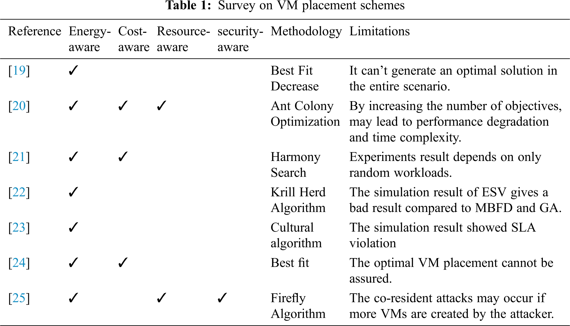
The different VM placement policy is proposed to minimize the co-resident of the attacker. Instead of using a VM placement method, a new VM placement policy technique is introduced, in which a VM placement policy will be chosen from the multiple VM placement policy pool based on the co-resident probability of attacker VM. In the secured VM placement technique, newly created VMs are deployed in the previously selected server. The Previously Selected Servers First (PSSF) technique maintained load balance by limiting the number of VM per user. The power consumption is also maintained by framing the fixed groups in the server. But, the legal user can create only a limited number of VMs. The PSSF technique reduces the co-residence of the attackers, but the server resource utilization is very less [18]. Tab. 1 highlights some of the correlated works and refers to their objectives, methodology, and limitations.
3 Co-resident Attack Scenarios
Let us assume, there is an ‘N’ number of servers. The ‘K’ number of VMs started by legitimate users {VML1, VML2 VML3 … VMLk} and ‘M’ number of VMs started by attackers {VMA1, VMA2 VMA3 … VMAM}. The target of an attacker is a set of VMs that is created by a legitimate user i.e., Target (A) = { VML1, VML2 VML3 … VMLk}. Let Hit_VM(A) denote the VM of the attacker A that co-located with at least one of the VM of the legitimate user. i.e., Hit_VM (A) = {V, | V VM(L), Server (V) }. Hit_Target (A) denote the VMs of the target user L that is co-located with at least one VM of the Attacker A. i.e., Hit_Target (A) = {x | x}. If any of the attacker VM (VMA) is co-located with the target VM (VML) then, the Hit_VM(A) and Hit_Target(A) will be non-empty. The hit of an attacker is measured in the following two dimensions,
(i) Efficiency: The efficiency of an attacker is defined as the number of PMs that are hosted by an attacker and co-located with at least one of the target VM (VML) divided by the total number of VMs hosted by the attacker.
(ii) Coverage: The coverage is defined as the number of target VMs co-located by the attacker VM, divided by the number of VMs allocated by the attacker.
We now describe and analyze our secure heuristics strategy. We divide all our existing PMs into some groups (μ). The placement of VM to PM is done in two steps: (i) Group Selection and (ii) PM Selection. The probability of Co-Resident in our strategy is defined as
In Eq. (3) we have
4 Objectives for Secure VM Placement
In our proposed MOSOVMP system, the VMs have been placed according to the following objectives: (i) Security (ii) Resource Wastage, and (iii) Power Consumption.
With the help of the cloud user database and the cloud user behaviour, the attacker is identified by CSP. The CSC attacker can be detected either with the help of our proposed system (Case A) [26] or with the user behaviour (Case B). Case A: The CRR is measured as follows: step (i): The vCPU utilization and virtual memory utilization of all VMs in a PM are measured and maximum utilized VMs are identified. Step (ii): The cache miss rate is measured with help of our previous work [26] while executing a sensitive operation (cryptography operation) in a VM. If the cache miss rate of a VM is high, the vCPU and virtual memory utilization of the co-resident VMs are also high, and then the co-resident VMs is identified as attackers. Case B: In our proposed system, the cloud user is classified into three types: (i) New user (ii) Trusted user: User creates a limited number of VMs. (iii) Un-trusted user: Even the VMs already created by the tenant are in an idle state. If a tenant is creating more VMs to achieve co-resident with the target user, then the tenant is identified as an Un-trusted user. And if a tenant is terminating some VMs and sending a request to create new VMs at the same time, then the tenant is identified as an Un-trusted user. To attain co-resident, the attackers try to place their VM with the victim VM in the following ways: (i) Brute-force approach: The attacker creates many VMs to attain co-resident. (ii) Start Time/Termination Time: If the VM created by the attacker does not co-locate with the target VM, then the attacker will terminate the existing VM and try to create new VMs to attain co-residence. (iii) Creating more VMs: The attacker creates more VMs at the same time to achieve co-residence.
The lingering resources accessible on each server may differ greatly with different VM placement strategies. To entirely utilize multi-dimensional resources, the following equation is used to measure the resource wastages:
RWK represents the resource wastage of the Kth server. The
The Power Consumption of an average data centre is estimated as much as 25,000 households [27] and it is expected to be double every five years [28]. Managing the servers in an energy-efficient way is critical to CSP to reduce the PC. This has been focused on the existing works [28–33]. Ristenpart introduced a power model to formulate the power consumption of all PMs [17]. The PC of a PM is calculated with a linear relationship of CPU utilization with the help of the Eq. (5).
The power consumption of servers is related to resources such as hard disk, CPU, and memory. Some research work specifies that the power consumption of hosts is a direct proposition with CPU utilization. Moreover, the research work also proposes that the power consumption of inactive PMs is about 70% of the power consumption below full load in Eq. (5), so the power consumption of PMs is defined as follows:
where
In Eq. (7) δi is specifies whether the ith PM is in use or not. If it is in use, δi = 1, otherwise, δi = 0.
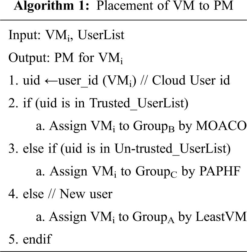
In Cloud Computing, there are two ways to place the VM in Physical Machine (PM). (i) Initial Placement: after receiving a VM request from the user, based on the VM placement policy the newly created VM is placed in the PM. (ii) Migration: The VM can be moved to another PM. The Cloud Service Provider (CSP) aims to minimize the co-residence of the attacker on the premise of balancing the work loaded and maintaining the low power consumption without SLA violation. The CSP groups (μ = 3) their Physical Machine as GroupA, GroupB, and GroupC for Unknown user, Trusted User, and Un-trusted User respectively. The VMs of unknown users are assigned in GroupA by using the Least VM placement policy. The VMs of trusted users are allocated in GroupB by using the Multi-Objective Ant Colony System (MOACO) The VMs of un-trusted users are allocated in GroupC by the Previously Assigned Physical Host First (PAPHF) algorithm. The proposed system working technique is given in Fig. 1. The procedure for selecting a group is given in Algorithm 1.
As the Least VM placement policy has a less co-resident rate, the new user VMs are placed in the PM of GroupA by Least VM placement policy. If the new user creates only a limited number of VMs in a specific time period, then the new user will be considered as a trusted user. The VMs of the new user will be migrated to GroupB.
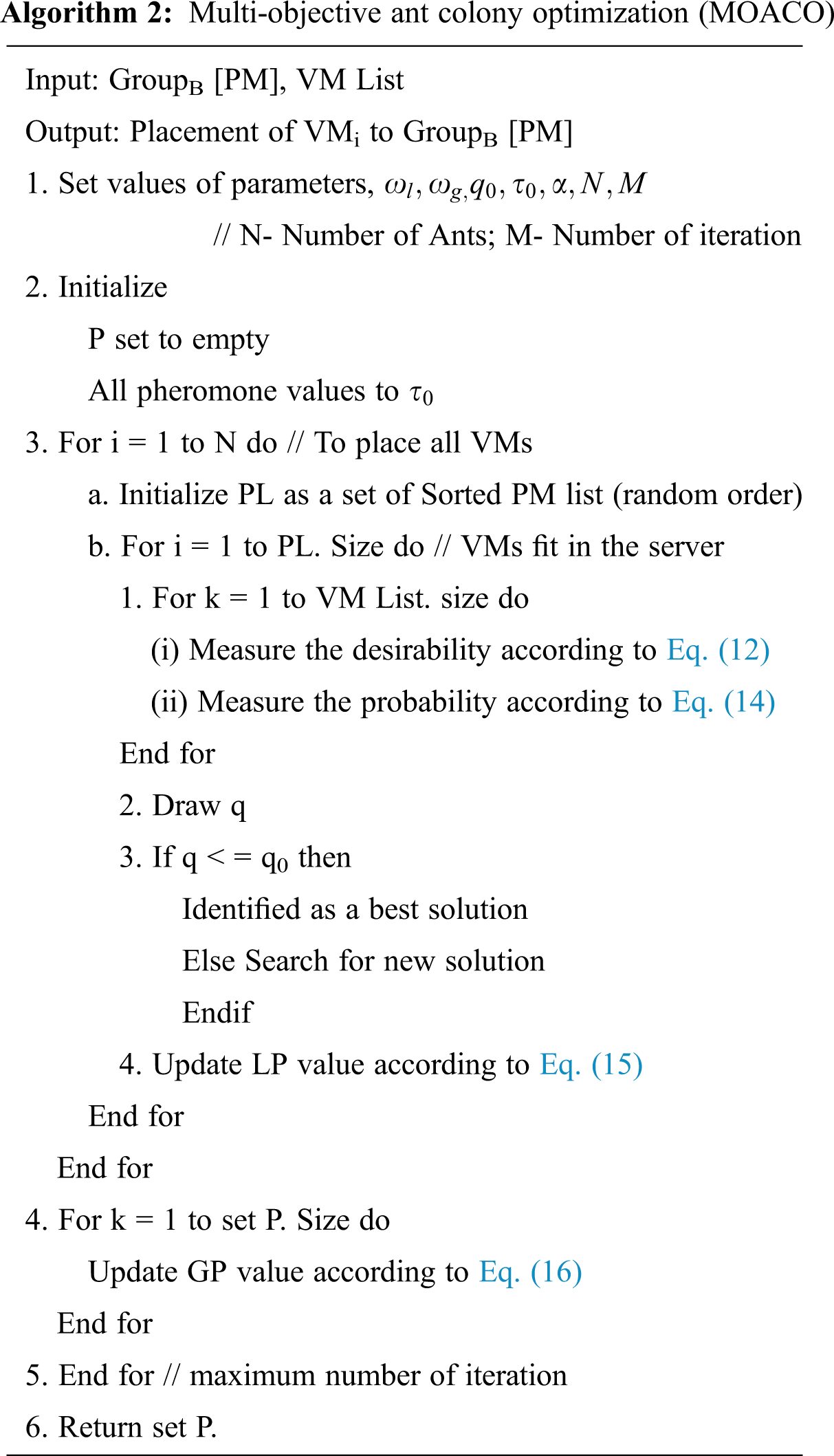
The VMs of the trusted user is placed in GroupB by MOACO policy. The MOACO policy simultaneously optimizes resource wastage (CPU and memory), and power consumption. A revised version of the ACO algorithm is designed to covenant effectively with the possible large resolution space. A feasible solution to the originated multi-objective VM placement problem is measured as a combination of all VM placements. The working procedure of the MOACO algorithm is explained in Algorithm 2. The parameters are initialized (
where n is the number of VMs. Sol0 is the solution generated by the First Fit Decreasing (FFD) heuristic, RW(Sol0 ) is Resource Wastage of Sol0 and PC’(Sol0) is the power consumption of Sol0. The Sol0 is measured as follows:

Figure 1: Proposed System—MOSOVMP workflow
The heuristic information is represented by
Therefore the total desirability of placing VMi to PMj is measured as follows:
In the method of making placements, the ant k picks a VMi as the next one to bundle to its current PMj based on the following PRP rule.
The α is a parameter that permits a user to manage the relative importance of the pheromone trail and q is a random number consistently distributed in [0, 1]. If the q value is greater than q0, then a new solution is searched, otherwise, an optimal solution is selected. q0 is a fixed parameter [0 ≤ q 0 ≤ 1] calculated by the comparative significance of exploitation of accrued information about the problem against to exploration of new travels. R is a random variable chosen based on the following PRP rule probability distribution [34], which is the probability that ant k selects to place VMi to PMj:
Another essential component of MOVMA is the update of Pheromone Trails (PT). The PT value can raise, as ants drop pheromone. It can drop off, due to pheromone evaporation. The deposit of new pheromone is depended on the information enclosed in some good solutions that should be shown by PT and the movement included in these good solutions will be influenced by other ants constructing subsequent solutions. In the proposed MPVMP algorithm, the pheromone updating method includes two steps: a LP update and a GP update. While assigning a placement of VMi to PMj, an ant shrinks the PT intensity between VMi and PMj by concerning the following LPU rule:
where τ0 is the initial pheromone level and
Then all results conquered by the added one are removed from the external set. N represents the number of ants and M represents the number of iteration. In Eq. (17), the adaptive coefficient
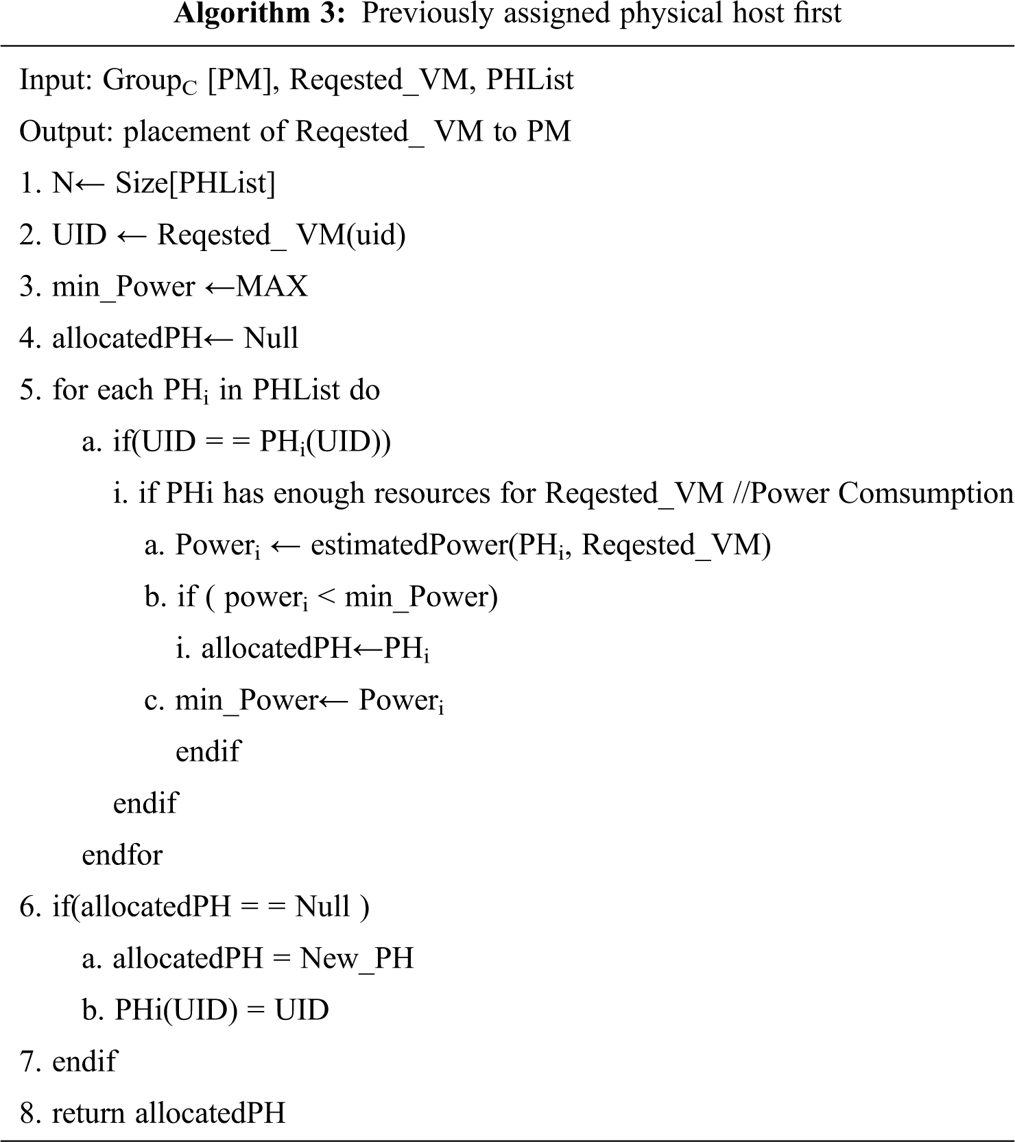
In GroupC, VMs are placed based on the PAPHF algorithm where the VMs of a specific user is only allowed into a Physical Machine. In GroupC, every Physical Machine has a unique user id. In PAPHF, the user id of the customer is compared with the user id of all the physical machines. If it matches any of the user ids of the PM, then the VM is allocated into that specific PM of GroupC. For example, The VM of user A is allocated to a PM of GroupC, Where the previous VM of user A pre-exists. If it doesn’t match with any of the user ids of the physical machines, then the VM is allocated into a new physical machine of GroupA. The VM of no two users is co-located in a PM. The PAPHF is explained in Algorithm 3. In PAPHF, the user id of the newly created VM is compared with the user id of the existing Physical Host (PH). If it is a match, then the resource request of the newly created VM is checked with the selected PH resources for compatibility. Otherwise, a new PH will be assigned for the new VM request in GroupA.
This research proposes to reduce the co-resident problem through different VM placement policies and also to improve server energy efficiency. The CloudSim toolkit [35] is a powerful simulation platform for the cloud computing environment. It also supports simulating various self-defined VM placement policies. Therefore, CloudSim is chosen to implement the proposed system. Each PM has one CPU core of 1000, 2500, or 3000 MIPS, and 8 GB of RAM. Each VM needs 128 MB of RAM, and one CPU core with 250, 500, 750 or 1000 MIPS. Three groups (μ) of VMs were created with a different number of the CPU core, MIPS, and RAM. After receiving the VM request of the customer, the CSP will identify its nature. Initially, basic VM placement policies were implemented and Co-Resident was evaluated (Fig. 2).
To identify the least possible Co-Resident placement policy, a set of VMs is placed by Random VM policy, Least VM policy, and Most VM policy. In this comparison, the least VM placement policy has less co-resident value compared to other policies. So, the least VM placement policy was chosen for the unknown users in the GroupA. Let ‘N’ be the number of VM created by unknown users. Let ‘M’ be the number of PMs assigned by N. By using the Least VM placement policy, a new VM is placed in the server, which has a fewer number of VMs. So, the number of PM is lesser than the number of the user (M < N). A legal user L starts 20 VMs at the 24,000th second (VM (L) = 20) and a certain time (
The VMs of the trusted users are placed in the PM by the MOACO placement policy. In the Multi-Objective ACO algorithm, PMs are selected based on PM energy efficiency and resource wastage. Trusted users may also try to get sensitive information about others. The co-resident detection system frequently monitors user behaviour. The attacker VMs are selected from the GroupB and named as VMA(B). i.e.,
Only one VM is placed per PM in the worst scenario. After the MOACO algorithm was completed, if there were some non dominated solutions, that solution fit in to the set of non dominated solutions was randomly selected. When number of PM = 47, number of VM = 50 number of ants N = 10, number of iteration = 10, α = 0.45,

Figure 2: Co-Resident for different VM placement policy
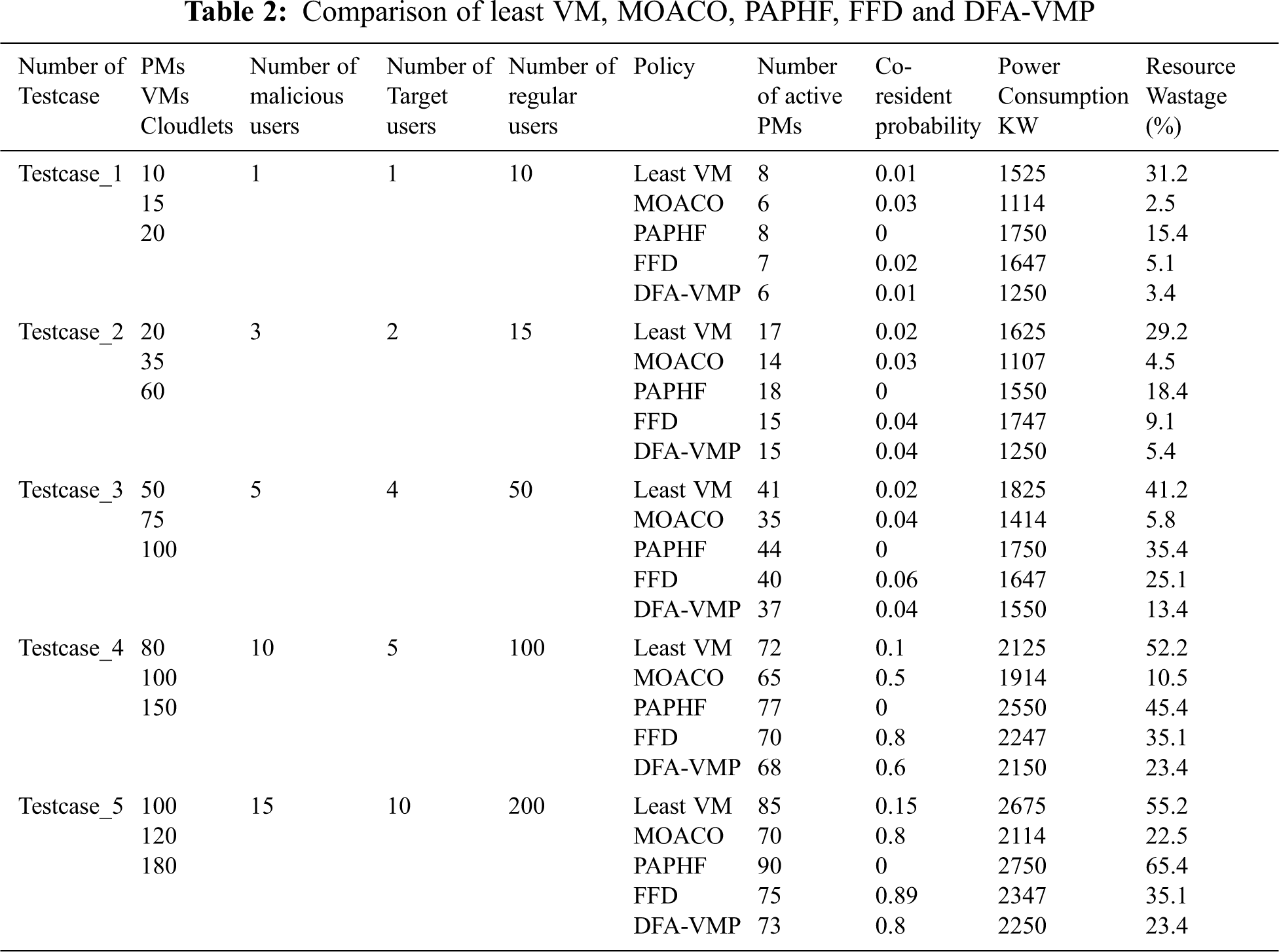
The power consumption of Least VM policy, MOACO, PAPHF, FFD and DFA-VMP is measured and showed (Fig. 3a). The power consumption of GroupA and GroupB is high while comparing to MOACO and DFA-VMP.

Figure 3: Comparison of Least VM, MOACO, PAPHF, FFD and DFA-VMP (a) Energy consumption (b) Resource wastage (c) Number of active VMs
The VMs of the Un-trusted user are placed in the PM by PSPF placement policy. Based on the user resource requirement, the PM will be selected. The server utilization of GroupC is very less. As we allocated the same PH (Physical Host) for the same user, the server utilization is lesser. Let ‘N’ be the number of VM created by Un-trusted users. Let ‘M' be the number of PMs assigned by N. By using the PSPF placement policy, the VMs are allocated in the PM based on their PM resource utilization and previously selected PM takes the first opportunity. So, the number of PM is less than or equal to the number of the user (M ≤ N). The power consumption and resource wastage of the PMs are measured in MOACO placement policy and compared with other placement policies (Figs. 3a and 3b). We experimented MOACO algorithm with different parameters for the same input to find suitable parameters for our problem. The number of active PMs also counted and compared for various placement policies (Fig. 3c). In DFA-VMP, the VMs are placed in PM by a discrete firefly algorithm [25]. They reduced power consumption and resource loss at the data centre. As we placed the VMs to PMs as per the user behaviour, the probability of placing malicious tenants and targeted tenants on the same physical host is very less compared to DFA-VMP. The co-resident probability is measured for the various placement policies. If the attacker creates more number of VMs, then the probability of co-resident also will be high. As the VM of the attacker is placed in GROUPC by the method of Previously Assigned Physical Host First, the co-resident is zero. But the power consumption and resource wastage are high in GROUPC (Fig. 4).

Figure 4: Comparison of Co-resident Probability for Least VM, MOACO, PAPHF, FFD and FA-VMP
This paper provides a new technique to reduce the Co-Resident of the attacker with the target user and also improves server utilization. Instead of finding a solution after co-locating the attackers with the target user, the cloud providers can mitigate the threat by minimizing the probability of attackers co-locating with the target. The existing solutions also give techniques for reducing the co-resident rate, but they have not considered the server utilization rate. Our proposed solution provides less co-resident and better server utilization. The frequent cloud CSCA attackers are identified and protected the secret information of the victim. Even though the power consumption and resource wastage of the new users and un-trusted users is high, the secrete information of the target users is protected from the attacker.
Funding Statement: The authors received no specific funding for this study.
Conflicts of Interest: The authors declare that they have no conflicts of interest to report regarding this study.
1. Y. Han, T. Alpcan, J. Chan and C. Leckie, “Security games for virtual machine allocation in cloud computing, ” in Decision and Game Theory for Security, Lecture Notes In Computer Science Series, vol. 8252, Springer International Publishing, pp. 99–118, 2013. [Google Scholar]
2. Y. Han, J. Chan, T. Alpcan and C. Leckie, “Using virtual machine allocation policies to defend against co- resident attacks in cloud computing,” IEEE Transactions on Dependable and Secure Computing, vol. 14, no. 1, pp. 95–108, 2017. [Google Scholar]
3. B. Vattikonda, S. Das and H. Shacham, “Eliminating fine grained timers in xen,” in Proc. of the Third ACM Workshop on Cloud Computing Security Workshop, Chicago, Illinois, USA, pp. 41–46, 2011. [Google Scholar]
4. J. Wu, L. Ding, Y. Lin, N. Min Allah and Y. Wang, “XenPump: A new method to mitigate timing channel in cloud computing,” in Proc. of the Fifth IEEE Int. Conf. on Cloud Computing, Honolulu, HI, USA, pp. 678–685, 2012. [Google Scholar]
5. A. Aviram, S. Hu, B. Ford and R. Gummadi, “Determinating timing channels in compute clouds,” in Proc. of the ACM Workshop on Cloud Computing Security Workshop, Chicago, Illinois, USA, pp. 103–108, 2012. [Google Scholar]
6. J. Wu, L. Ding, Y. Wang and W. Han, “Identification and evaluation of sharing memory covert timing channel in xen virtual machines,” in Proc. of the Fourth IEEE Int. Conf. on Cloud Computing, Washington, DC, USA, pp. 283–291, 2011. [Google Scholar]
7. G. Daniel, L. Valenta and Y. Yarom, “May the fourth be with you: A microarchitectural side channel attack on several real-world applications of curve25519,” in Proc. of ACM SIGSAC Conf. on Computer and Communications Security, Dallas, Texas, USA, pp. 845–858, 2017. [Google Scholar]
8. A. Hameed, A. Khoshkbarforoushha, R. Ranjan, P. Jayaraman, J. Kolodziej et al., “A survey and taxonomy on energy efficient resource allocation techniques for cloud computing systems,” Computing, vol. 98, no. 7, pp. 751–774, 2014. [Google Scholar]
9. P. Graubner, “Energy-efficient management of virtual machines in eucalyptus,” in Proc. of the IEEE Fourth Int. Conf. on Cloud Computing, Washington, DC, USA, pp. 243–250, 2011. [Google Scholar]
10. R. Jansen and P. R. Brenner, “Energy efficient virtual machine allocation in the cloud: An analysis of cloud allocation policies,” in Proc. of the Int. Green Computing Conf. and Workshops, Orlando, FL, USA, pp. 1–8, 2011. [Google Scholar]
11. K. Le, R. Bianchini, J. Zhang, Y. Jaluria, J. Meng et al., “Reducing electricity cost through virtual machine placement in high performance computing clouds,” in Proc. of the Int. Conf. for High Performance Computing, Networking, Storage and Analysis, Seattle, WA, USA, pp. 1–12, 2011. [Google Scholar]
12. K. Mills, J. Filliben and C. Dabrowski, “Comparing VM-placement algorithms for on-demand clouds,” in Proc. of the IEEE Third Int. Conf. on Cloud Computing Technology and Science, United States, pp. 91–98, 2011. [Google Scholar]
13. A. Beloglazov, J. Abawajy and R. Buyya, “Energy-aware resource allocation heuristics for efficient management of data centers for cloud computing,” Future Generation Computer Systems, vol. 28, no. 5, pp. 755–768, 2012. [Google Scholar]
14. Y. Zhang, M. Li, K. Bai, M. Yu and W. Zhang, “Incentive compatible moving target defense against VM-colocation attacks in clouds,” IFIP Advances in Information and Communication Technology book series, vol. 376, pp. 388–399, 2012. [Google Scholar]
15. Y. Zhang and M. K. Reiter, “Düppel: Retrofitting commodity operating systems to mitigate cache side channels in the cloud,” in Proc. of the ACM SIGSAC Conf. on Computer & Communications Security, Berlin, Germany, pp. 827–838, 2013. [Google Scholar]
16. A. Beloglazov and R. Buyya, “Optimal online deterministic algorithms and adaptive heuristics for energy and performance efficient dynamic consolidation of virtual machines in Cloud data centers,” Concurrency Computation Practice Experience, vol. 24, no. 13, pp. 1397–1420, 2012. [Google Scholar]
17. T. Ristenpart, E. Tromer, H. Shacham and S. Savae, “Hey, you, get off of my cloud: Exploring information leakage in third-party compute clouds,” in Proc. of the ACM Conf. on Computer and Communications Security (CCSChicago, Illinois, USA, pp. 199–221, 2009. [Google Scholar]
18. Y. C. Lee and A. Y. Zomaya, “Energy efficient utilization of resources in cloud computing systems,” Journal of Supercomputing, Springer, vol. 60, no. 2, pp. 268–280, 2012. [Google Scholar]
19. A. Beloglazov, J. Abawajy and R. Buyya, “‘Energy-aware resource allocation heuristics for efficient management of data centers for cloud computing,” Future Generation Computer Systems, vol. 28, no. 5, pp. 755–768, 2012. [Google Scholar]
20. M. H. Malekloo, N. Kara and M. El Barachi, “An energy efficient and SLA compliant approach for resource allocation and consolidation in cloud computing environments,” Sustainable Computing: Informatics and Systems, vol. 17, no. 1, pp. 9–24, 2018. [Google Scholar]
21. M. H. Fathi and L. M. Khanli, “Consolidating VMs in green cloud computing using harmony search algorithm,” in Proc. of the Int. Conf. on Internet and e-Business (ICIEBNew York, NY, USA, pp. 146–151, 2018. [Google Scholar]
22. M. Soltanshahi, R. Asemi and N. Shafiei, “Energy-aware virtual machines allocation by krill herd algorithm in cloud data centers,” An open access Journal, Elsevier, Heliyon, cell press, vol. 5, no. 7, 2019. [Google Scholar]
23. M. Mohammadhosseini, A. Toroghi Haghighat and E. Mahdipour, “An efficient energy-aware method for virtual machine placement in cloud data centers using the cultural algorithm,” Journal of Supercomputing, vol. 75, no. 10, pp. 6904–6933, 2019. [Google Scholar]
24. N. Garg, D. Singh and M. S. Goraya, “Power and resource-aware VM placement in cloud environment,” in Proc. of the IEEE 8th Int. Advance Computing Conf. (IACCGreater Noida, India, pp. 113–118, 2018. [Google Scholar]
25. W. Ding, C. Gu, F. Luo, Y. Chang, U. Rugwiro et al., “DFA-VMP: An efficient and secure virtual machine placement strategy under cloud environment,” Peer-to-Peer Networking and Applications, vol. 11, no. 2, pp. 318–333, 2018. [Google Scholar]
26. G. Sangeetha and G. Sumathi, “An optimistic technique to detect cache based side channel attacks in cloud,” Peer-to-Peer Networking and Applications. [Online].2020.https://doi.org/10.1007/s12083-020-00996-1. [Google Scholar]
27. J. M. Kaplan, W. Forrest and N. Kindler, Revolutionizing data center energy efficiency,Technical Report.New York, NY, USA: McKinsey & Company, 2008. [Google Scholar]
28. A. Beloglazov and R. Buyya, “Energy efficient resource management in virtualized cloud data centers,” in Proc. of 10th IEEE/ACM Int. Conf. on Cluster, Cloud and Grid Computing, Melbourne, VIC, Australia, pp. 826–831, 2010. [Google Scholar]
29. P. Graubner, “Energy-efficient management of virtual machines in eucalyptus,” in Proc. of the IEEE 4th Int. Conf. on Cloud Computing, Washington, DC, USA, pp. 243–250, 2011. [Google Scholar]
30. R. Jansen and P. R. Brenner, “Energy efficient virtual machine allocation in the cloud: An analysis of cloud allocation policies,” in Proc. of the Int. Green Computing Conf. and Workshops, Orlando, FL, USA, pp. 1–8, 2011. [Google Scholar]
31. K. Le, R. Bianchini, J. Zhang, Y. Jaluria, J. Meng et al., “Reducing electricity cost through virtual machine placement in high performance computing clouds,” in Proc. of the Int. Conf. for High Performance Computing, Networking, Storage and Analysis, Seattle, WA, USA, pp. 1–12, 2011. [Google Scholar]
32. K. Mills, J. Filliben and C. Dabrowski, “Comparing VM-placement algorithms for on-demand clouds,” in Proc. of the IEEE Third Int. Conf. on Cloud Computing Technology and Science, Athens, Greece, pp. 91–98, 2011. [Google Scholar]
33. A. Beloglazov, J. Abawajy and R. Buyya, “Energy-aware resource allocation heuristics for efficient management of data centers for cloud computing,” Future Generation Computer Systems, vol. 28, no. 5, pp. 755–768, 2012. [Google Scholar]
34. V. Maniezzo, “Exact and approximate nondeterministic tree-search procedures for the quadratic assignment problem,” INFORMS Journal on Computing, vol. 11, no. 4, pp. 358–369, 1998. [Google Scholar]
35. R. Calheiros, R. Ranjan, A. Beloglazov, C. A. F. De Rose and R. Buyya, “CloudSim: A toolkit for modeling and simulation of cloud computing environments and evaluation of resource provisioning algorithms,” Software Practice and Experience, vol. 41, no. 1, pp. 23–50, 2011. [Google Scholar]
 | This work is licensed under a Creative Commons Attribution 4.0 International License, which permits unrestricted use, distribution, and reproduction in any medium, provided the original work is properly cited. |